
User Manual
Page 2
... the products and software described in any form or by any means, except documentation kept by ASUS; ASUS ASSUMES NO RESPONSIBILITY OR LIABILITY FOR ANY ERRORS OR INACCURACIES THAT MAY APPEAR IN THIS MANUAL, INCLUDING THE PRODUCTS AND SOFTWARE DESCRIBED IN IT. ii All Rights Reserved. or (2) the ...serial number of ASUSTeK COMPUTER INC. ("ASUS"). ASUS PROVIDES THIS MANUAL "AS IS" WITHOUT WARRANTY OF ANY KIND, EITHER EXPRESS OR IMPLIED, INCLUDING BUT NOT LIMITED TO THE IMPLIED WARRANTIES OR CONDITIONS ...
... the products and software described in any form or by any means, except documentation kept by ASUS; ASUS ASSUMES NO RESPONSIBILITY OR LIABILITY FOR ANY ERRORS OR INACCURACIES THAT MAY APPEAR IN THIS MANUAL, INCLUDING THE PRODUCTS AND SOFTWARE DESCRIBED IN IT. ii All Rights Reserved. or (2) the ...serial number of ASUSTeK COMPUTER INC. ("ASUS"). ASUS PROVIDES THIS MANUAL "AS IS" WITHOUT WARRANTY OF ANY KIND, EITHER EXPRESS OR IMPLIED, INCLUDING BUT NOT LIMITED TO THE IMPLIED WARRANTIES OR CONDITIONS ...

User Manual
Page 6
... DVD 4-1 4.2.2 Drivers menu 4-2 4.2.3 Utilities menu 4-3 4.2.4 Make disk menu 4-5 4.2.5 Manual menu 4-6 4.2.6 ASUS Contact information 4-6 4.2.7 Other information 4-7 4.3 Software information 4-9 4.3.1 ASUS MyLogo 2 4-9 4.3.2 ASUS PC Probe II 4-11 4.3.3 ASUS AI Suite 4-17 4.3.4 ASUS AI Nap 4-19 4.3.5 ASUS Fan Xpert 4-20 4.3.6 ASUS EPU-6 Engine 4-22 4.3.7 ASUS TurboV 4-26 4.3.8 Audio configurations 4-28 4.3.9 ASUS Express Gate 4-36 4.3.10 ASUS Drive Xpert 4-43 4.4 RAID configurations 4-47 4.4.1 RAID definitions 4-47...
... DVD 4-1 4.2.2 Drivers menu 4-2 4.2.3 Utilities menu 4-3 4.2.4 Make disk menu 4-5 4.2.5 Manual menu 4-6 4.2.6 ASUS Contact information 4-6 4.2.7 Other information 4-7 4.3 Software information 4-9 4.3.1 ASUS MyLogo 2 4-9 4.3.2 ASUS PC Probe II 4-11 4.3.3 ASUS AI Suite 4-17 4.3.4 ASUS AI Nap 4-19 4.3.5 ASUS Fan Xpert 4-20 4.3.6 ASUS EPU-6 Engine 4-22 4.3.7 ASUS TurboV 4-26 4.3.8 Audio configurations 4-28 4.3.9 ASUS Express Gate 4-36 4.3.10 ASUS Drive Xpert 4-43 4.4 RAID configurations 4-47 4.4.1 RAID definitions 4-47...

User Manual
Page 9
... the crossed out wheeled bin indicates that all power cables from the existing system before using the product, make sure all the manuals that the product (electrical and electronic equipment) should not be placed in any damage, contact your retailer. ix Safety information Electrical..., and temperature extremes. DO NOT throw the mercury-containing button cell battery in municipal waste. DO NOT throw the motherboard in municipal waste. This symbol of electronic products. If possible, disconnect all power cables are connected. This symbol of parts and recycling.
... the crossed out wheeled bin indicates that all power cables from the existing system before using the product, make sure all the manuals that the product (electrical and electronic equipment) should not be placed in any damage, contact your retailer. ix Safety information Electrical..., and temperature extremes. DO NOT throw the mercury-containing button cell battery in municipal waste. DO NOT throw the motherboard in municipal waste. This symbol of electronic products. If possible, disconnect all power cables are connected. This symbol of parts and recycling.

User Manual
Page 11
...-than and greater-than sign means that you must type the command exactly as shown, then supply the required item or value enclosed in this manual. IMPORTANT: Instructions that you must press two or more keys simultaneously, the key names are linked with a plus sign (+). Example: Means that you complete a task...
...-than and greater-than sign means that you must type the command exactly as shown, then supply the required item or value enclosed in this manual. IMPORTANT: Instructions that you must press two or more keys simultaneously, the key names are linked with a plus sign (+). Example: Means that you complete a task...
User Manual
Page 12
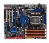
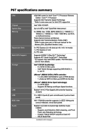
...; Technology* Supports ATI® Quad CrossFireX™ Technology * SLI support may need BIOS update. com for up to 6.4GT/s; P6T specifications summary CPU Chipset System Bus Memory Expansion Slots Multi-GPU Support Storage LAN USB IEEE 1394 Audio LGA1366 socket for Intel® ... memory architecture Supports Intel® Extreme Memory Profile (XMP) * Refer to www.asus.com or this user manual for the Memory QVL (Qualified Vendors Lists) 3 x PCI Express 2.0 x16 slots (at back I/O - Visit www.asus. Intel® Matrix Storage supporting SATA RAID 0,1, 5, and 10 JMicron® ...
...; Technology* Supports ATI® Quad CrossFireX™ Technology * SLI support may need BIOS update. com for up to 6.4GT/s; P6T specifications summary CPU Chipset System Bus Memory Expansion Slots Multi-GPU Support Storage LAN USB IEEE 1394 Audio LGA1366 socket for Intel® ... memory architecture Supports Intel® Extreme Memory Profile (XMP) * Refer to www.asus.com or this user manual for the Memory QVL (Qualified Vendors Lists) 3 x PCI Express 2.0 x16 slots (at back I/O - Visit www.asus. Intel® Matrix Storage supporting SATA RAID 0,1, 5, and 10 JMicron® ...

User Manual
Page 54
See section 3.3.6 Storage Configuration for details. • Before creating a RAID set, refer to section 4.4.3 Intel RAID configurations or the manual bundled in the BIOS to [AHCI]. ICH10R Serial ATA connectors [red] (7-pin SATA 1-6) These connectors are for the Serial ATA signal cables for details. 2-30 .... • These connectors are using Windows® XP or later version. • When using hot-plug and NCQ, set the Configure SATA as in the motherboard support DVD. • You must install the Windows® XP Service Pack 1 before using these connectors.
See section 3.3.6 Storage Configuration for details. • Before creating a RAID set, refer to section 4.4.3 Intel RAID configurations or the manual bundled in the BIOS to [AHCI]. ICH10R Serial ATA connectors [red] (7-pin SATA 1-6) These connectors are for the Serial ATA signal cables for details. 2-30 .... • These connectors are using Windows® XP or later version. • When using hot-plug and NCQ, set the Configure SATA as in the motherboard support DVD. • You must install the Windows® XP Service Pack 1 before using these connectors.

User Manual
Page 85
...for optimizing the system performance. Scroll down to overclock DRAM frequency by adjusting BCLK frequency. ASUS P6T 3-17 Select either one of the following items: DRAM CTRL REF Voltage on CHA [...display the following items vary depending on the CPU and memory modules you install on the motherboard. BIOS SETUP UTILITY Main Ai Tweaker Advanced Power Boot Tools Exit Configure System Performance Settings...the preset overclocking configuration options: Manual Auto D.O.C.P X.M.P. is enabled BLCK frequency, CPU ratio and memory parameters will be auto optimized.
...for optimizing the system performance. Scroll down to overclock DRAM frequency by adjusting BCLK frequency. ASUS P6T 3-17 Select either one of the following items: DRAM CTRL REF Voltage on CHA [...display the following items vary depending on the CPU and memory modules you install on the motherboard. BIOS SETUP UTILITY Main Ai Tweaker Advanced Power Boot Tools Exit Configure System Performance Settings...the preset overclocking configuration options: Manual Auto D.O.C.P X.M.P. is enabled BLCK frequency, CPU ratio and memory parameters will be auto optimized.

User Manual
Page 86
... Chapter 3: BIOS setup The values range from 100 to adjust the value. DIMM or 1600MHz DIMM, install only one DIMM on the motherboard. When set to adjust the ratio between CPU Core Clock and BCLK Frequency. The configuration options for the following two items appear only... when you set the Ai Overclock Tuner item to [Manual], [D.O.C.P.] or [X.M.P.]. Configuration options: [DDR3-2006MHz] [DDR3-1805MHz] eXtreme Memory Profile [High Performance] This item appears only when you set ...
... Chapter 3: BIOS setup The values range from 100 to adjust the value. DIMM or 1600MHz DIMM, install only one DIMM on the motherboard. When set to adjust the ratio between CPU Core Clock and BCLK Frequency. The configuration options for the following two items appear only... when you set the Ai Overclock Tuner item to [Manual], [D.O.C.P.] or [X.M.P.]. Configuration options: [DDR3-2006MHz] [DDR3-1805MHz] eXtreme Memory Profile [High Performance] This item appears only when you set ...

User Manual
Page 122
Install the Adobe® Acrobat® Reader from the Utilities menu before opening a user manual file. 4.2.6 ASUS Contact information Click the Contact tab to open the folder of the user manual. Most user manual files are in Portable Document Format (PDF). You can also find this information on the inside front cover of supplementary user manuals. 4.2.5 Manual menu The Manual menu contains a list of this user guide. 4-6 Chapter 4: Software support Click an item to display the ASUS contact information.
Install the Adobe® Acrobat® Reader from the Utilities menu before opening a user manual file. 4.2.6 ASUS Contact information Click the Contact tab to open the folder of the user manual. Most user manual files are in Portable Document Format (PDF). You can also find this information on the inside front cover of supplementary user manuals. 4.2.5 Manual menu The Manual menu contains a list of this user guide. 4-6 Chapter 4: Software support Click an item to display the ASUS contact information.

User Manual
Page 142
Use the Save Profile function to save your customized overclocking settings and manually load the profile after Windows starts. • For system stability, set ASUS EPU 6-Engine to High Performance Mode while using TurboV. • The BCLK Frequency setting in BIOS affects the adjustable ...BIOS below 200MHz for an adjustment range from the motherboard support DVD. 2. Save the current settings as a profile Voltage Adjustment bars Shows more settings Default settings Target settings Applies all changes immediately Undoes all changes made in ASUS TurboV will not be saved to the CPU ...
Use the Save Profile function to save your customized overclocking settings and manually load the profile after Windows starts. • For system stability, set ASUS EPU 6-Engine to High Performance Mode while using TurboV. • The BCLK Frequency setting in BIOS affects the adjustable ...BIOS below 200MHz for an adjustment range from the motherboard support DVD. 2. Save the current settings as a profile Voltage Adjustment bars Shows more settings Default settings Target settings Applies all changes immediately Undoes all changes made in ASUS TurboV will not be saved to the CPU ...

User Manual
Page 143
... main screen to display detailed configuration options for manual CPU ratio adjustment. This is due to [Auto] before using the CPU Ratio function in CPU Ratio Mode may turn off this feature in BIOS for CPU/chip voltage, DRAM Reference voltage, and CPU ratio. ASUS P6T 4-27 You may be higher than your...
... main screen to display detailed configuration options for manual CPU ratio adjustment. This is due to [Auto] before using the CPU Ratio function in CPU Ratio Mode may turn off this feature in BIOS for CPU/chip voltage, DRAM Reference voltage, and CPU ratio. ASUS P6T 4-27 You may be higher than your...

User Manual
Page 152
... after you power on SATA HDDs in IDE or SATA mode only. The Drivers installation tab appears if your motherboard user manual for details. • ASUS Express Gate supports HDDs or ODDs connected to motherboard chipset-controlled onboard SATA ports only. Follow the screen instructions to install Express Gate. To install Express Gate on...
... after you power on SATA HDDs in IDE or SATA mode only. The Drivers installation tab appears if your motherboard user manual for details. • ASUS Express Gate supports HDDs or ODDs connected to motherboard chipset-controlled onboard SATA ports only. Follow the screen instructions to install Express Gate. To install Express Gate on...

User Manual
Page 155
... DSL/cable modem (no router in the SSID field. Otherwise, click Setup to configure the static IP settings manually. • WiFi settings (if supported): If your motherboard supports wireless network, click Setup for xDSL/cable dial-up (PPPoE) settings: If you use a network cable...in the Encryption Type field, and enter the password. ASUS P6T 4-39 Click OK to enable xDSL/ cable dial-up account. To configure network settings 1. Express Gate will automatically be working, you don't need to manually configure network settings. If you computer automatically obtains network settings...
... DSL/cable modem (no router in the SSID field. Otherwise, click Setup to configure the static IP settings manually. • WiFi settings (if supported): If your motherboard supports wireless network, click Setup for xDSL/cable dial-up (PPPoE) settings: If you use a network cable...in the Encryption Type field, and enter the password. ASUS P6T 4-39 Click OK to enable xDSL/ cable dial-up account. To configure network settings 1. Express Gate will automatically be working, you don't need to manually configure network settings. If you computer automatically obtains network settings...

User Manual
Page 178
If your motherboard has more than two PCIEX16 slots, refer to the goldfingers on the slots. 4. Connect a VGA or a DVI cable to the two graphics cards separately. 6. Insert the two graphics card into the PCIEX16 slots. Ensure that the connector is firmly in this user manual for the ...installation. 3. CrossFireX bridge Goldfingers 5. Align and firmly insert the CrossFireX bridge connector to Chapter 2 in place. The graphics cards and the motherboard layout may vary with models, but the installation steps remain the same. 1. Prepare two CrossFireX-ready graphics cards. 2.
If your motherboard has more than two PCIEX16 slots, refer to the goldfingers on the slots. 4. Connect a VGA or a DVI cable to the two graphics cards separately. 6. Insert the two graphics card into the PCIEX16 slots. Ensure that the connector is firmly in this user manual for the ...installation. 3. CrossFireX bridge Goldfingers 5. Align and firmly insert the CrossFireX bridge connector to Chapter 2 in place. The graphics cards and the motherboard layout may vary with models, but the installation steps remain the same. 1. Prepare two CrossFireX-ready graphics cards. 2.

User Manual
Page 179
ASUS P6T 5-3 5.1.4 Installing three CrossFireX graphics cards 1. Align and firmly insert the two CrossFireX bridge connectors to the graphics card. Connect a VGA or a DVI cable to the goldfingers on the slots. 4. If your motherboard has more than three PCIEX16 slots, refer to the three graphics cards ...separately. 6. Prepare three CrossFireX-ready graphics cards. 2. Insert the three graphics card into the PCIEX16 slots. Ensure that the cards are firmly in this user manual for the ...
ASUS P6T 5-3 5.1.4 Installing three CrossFireX graphics cards 1. Align and firmly insert the two CrossFireX bridge connectors to the graphics card. Connect a VGA or a DVI cable to the goldfingers on the slots. 4. If your motherboard has more than three PCIEX16 slots, refer to the three graphics cards ...separately. 6. Prepare three CrossFireX-ready graphics cards. 2. Insert the three graphics card into the PCIEX16 slots. Ensure that the cards are firmly in this user manual for the ...

User Manual
Page 183
...multi-graphics card installation. 3. Connect two independent auxiliary power sources from the power supply to the graphics card. SLI bridge Goldfingers ASUS P6T 5-7 If your motherboard has more than two PCIEX16 slots, refer to the goldfingers on the slots. 4. The graphics cards and the...the same. 1. Align and firmly insert the SLI bridge connector to Chapter 2 in place. 5. Ensure that the connector is firmly in this user manual for the locations of the PCIEX16 slots recommended for reference only. Connect a VGA or a DVI cable to the two graphics cards separately. 6. ...
...multi-graphics card installation. 3. Connect two independent auxiliary power sources from the power supply to the graphics card. SLI bridge Goldfingers ASUS P6T 5-7 If your motherboard has more than two PCIEX16 slots, refer to the goldfingers on the slots. 4. The graphics cards and the...the same. 1. Align and firmly insert the SLI bridge connector to Chapter 2 in place. 5. Ensure that the connector is firmly in this user manual for the locations of the PCIEX16 slots recommended for reference only. Connect a VGA or a DVI cable to the two graphics cards separately. 6. ...

User Manual
Page 184
... cards separately. 6. Prepare three SLI-ready graphics cards. 2. Ensure that the connector is firmly in this user manual for the locations of the PCIEX16 slots recommended for multi-graphics card installation. 3. If your motherboard has more than two PCIEX16 slots, refer to the goldfingers on the slots. 4. Connect three independent auxiliary power...
... cards separately. 6. Prepare three SLI-ready graphics cards. 2. Ensure that the connector is firmly in this user manual for the locations of the PCIEX16 slots recommended for multi-graphics card installation. 3. If your motherboard has more than two PCIEX16 slots, refer to the goldfingers on the slots. 4. Connect three independent auxiliary power...


