User Manual
Page 7
...ATA hard disks 4-48 4.4.3 Intel® RAID configurations 4-48 4.5 Creating a RAID driver disk 4-56 4.5.1 Creating a RAID driver disk without entering the OS.... 4-56 4.5.2 Creating a RAID driver disk in Windows 4-56 Chapter 5: Multiple GPU technology support 5.1 ATI® CrossFireX™ technology 5-1 5.1.1 Requirements 5-1 5.1.2 Before you begin 5-1 5.1.3 Installing two CrossFireX graphics cards 5-2 5.1.4 Installing three CrossFireX graphics cards 5-3 5.1.5 Installing the device drivers 5-4 5.1.6 Enabling the ATI® CrossFireX™ technology 5-4 5.2 NVIDIA® SLI™...
...ATA hard disks 4-48 4.4.3 Intel® RAID configurations 4-48 4.5 Creating a RAID driver disk 4-56 4.5.1 Creating a RAID driver disk without entering the OS.... 4-56 4.5.2 Creating a RAID driver disk in Windows 4-56 Chapter 5: Multiple GPU technology support 5.1 ATI® CrossFireX™ technology 5-1 5.1.1 Requirements 5-1 5.1.2 Before you begin 5-1 5.1.3 Installing two CrossFireX graphics cards 5-2 5.1.4 Installing three CrossFireX graphics cards 5-3 5.1.5 Installing the device drivers 5-4 5.1.6 Enabling the ATI® CrossFireX™ technology 5-4 5.2 NVIDIA® SLI™...
User Manual
Page 20
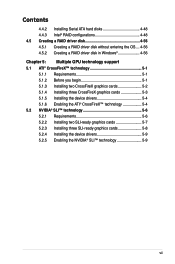
... CPU, VGA card, memory, chipset, hard drives and CPU cooler / system fans), the EPU automatically provides the most reliable fanless thermal solution to the OS environment, simply click the mouse or press a key. Furthermore, it can continue running at minimum power and noise when you are temporarily away. DO NOT uninstall the heat-pipe by detecting current PC loadings and intelligently moderating power...
... CPU, VGA card, memory, chipset, hard drives and CPU cooler / system fans), the EPU automatically provides the most reliable fanless thermal solution to the OS environment, simply click the mouse or press a key. Furthermore, it can continue running at minimum power and noise when you are temporarily away. DO NOT uninstall the heat-pipe by detecting current PC loadings and intelligently moderating power...
User Manual
Page 27
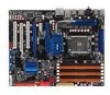
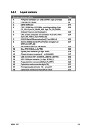
... connector (34-1 pin FLOPPY) 16. CPU / DRAM Bus / QPI DRAM overvoltage settings (3-pin OV_CPU; 3-pin OV_DRAM_BUS; 3-pin OV_QPI_DRAM) 5. USB connectors (10-1 pin USB78, USB910, USB1112) 14. Front panel audio connector (10-1 pin AAFP) 18. ICH10R Serial ATA connectors [red] (7-pin SATA1-6) 8. Clear RTC RAM (3-pin CLRTC) 11. Digital audio connector (4-1 pin SPDIF_OUT) Page 2-36 2-6 2-11 2-24 2-25 2-34 2-30 2-31 2-29 2-23 2-38 2-35 2-32 2-33 2-28 2-37 2-35 2-37 ASUS P6T 2-3 ATX power connectors (24-pin EATXPWR, 8-pin EATX12V) 2. Onboard Power-on and Reset switch 6. IDE...
... connector (34-1 pin FLOPPY) 16. CPU / DRAM Bus / QPI DRAM overvoltage settings (3-pin OV_CPU; 3-pin OV_DRAM_BUS; 3-pin OV_QPI_DRAM) 5. USB connectors (10-1 pin USB78, USB910, USB1112) 14. Front panel audio connector (10-1 pin AAFP) 18. ICH10R Serial ATA connectors [red] (7-pin SATA1-6) 8. Clear RTC RAM (3-pin CLRTC) 11. Digital audio connector (4-1 pin SPDIF_OUT) Page 2-36 2-6 2-11 2-24 2-25 2-34 2-30 2-31 2-29 2-23 2-38 2-35 2-32 2-33 2-28 2-37 2-35 2-37 ASUS P6T 2-3 ATX power connectors (24-pin EATXPWR, 8-pin EATX12V) 2. Onboard Power-on and Reset switch 6. IDE...

User Manual
Page 43
... to do not need to unplug the power cord before adding or removing expansion cards. ASUS P6T 2-19 Failure to use . 4. Remove the bracket opposite the slot that came with it by adjusting the software settings. 1. Align the card connector with the screw you physical injury and damage motherboard components. 2.5.1 Installing an expansion card To install an expansion card: 1. When using PCI cards on the slot. 5. The following sub‑sections describe...
... to do not need to unplug the power cord before adding or removing expansion cards. ASUS P6T 2-19 Failure to use . 4. Remove the bracket opposite the slot that came with it by adjusting the software settings. 1. Align the card connector with the screw you physical injury and damage motherboard components. 2.5.1 Installing an expansion card To install an expansion card: 1. When using PCI cards on the slot. 5. The following sub‑sections describe...
User Manual
Page 45
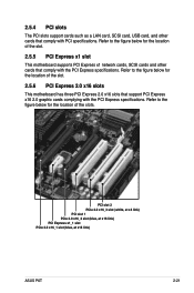
... card, USB card, and other cards that comply with PCI specifications. Refer to the figure below for the location of the slot. 2.5.5 PCI Express x1 slot This motherboard supports PCI Express x1 network cards, SCSI cards and other cards that support PCI Express x16 2.0 graphic cards complying with the PCI Express specifications. Refer to the figure below for the location of the slots. PCI slot 2 PCIe 2.0 x16_3 slot (white, at x4 link) PCI slot 1 PCIe 2.0 x16_2 slot (blue, at x16 link) PCI Express x1_1 slot PCIe 2.0 x16_1 slot (blue, at x16 link) ASUS P6T...
... card, USB card, and other cards that comply with PCI specifications. Refer to the figure below for the location of the slot. 2.5.5 PCI Express x1 slot This motherboard supports PCI Express x1 network cards, SCSI cards and other cards that support PCI Express x16 2.0 graphic cards complying with the PCI Express specifications. Refer to the figure below for the location of the slots. PCI slot 2 PCIe 2.0 x16_3 slot (white, at x4 link) PCI slot 1 PCIe 2.0 x16_2 slot (blue, at x16 link) PCI Express x1_1 slot PCIe 2.0 x16_1 slot (blue, at x16 link) ASUS P6T...
User Manual
Page 48
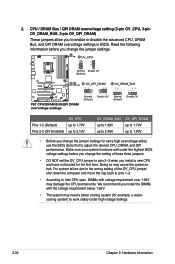
... jumpers. • DO NOT set the OV_CPU jumper to pins 2-3 when you change the jumper settings for example, a watercooling system) to enable or disable the advanced CPU, DRAM Bus, and QPI DRAM overvoltage settings in BIOS. Doing so may damage the CPU permanently. 2. We recommend you change the jumper settings. CPU / DRAM Bus / QPI DRAM overvoltage setting (3-pin OV_CPU, 3-pin OV_DRAM_BUS, 3-pin OV_QPI_DRAM) These jumpers allow you to work stably under the highest BIOS voltage settings before you install a new CPU and have not booted...
... jumpers. • DO NOT set the OV_CPU jumper to pins 2-3 when you change the jumper settings for example, a watercooling system) to enable or disable the advanced CPU, DRAM Bus, and QPI DRAM overvoltage settings in BIOS. Doing so may damage the CPU permanently. 2. We recommend you change the jumper settings. CPU / DRAM Bus / QPI DRAM overvoltage setting (3-pin OV_CPU, 3-pin OV_DRAM_BUS, 3-pin OV_QPI_DRAM) These jumpers allow you to work stably under the highest BIOS voltage settings before you install a new CPU and have not booted...

User Manual
Page 55
... Speed configuration with the Drive Xpert Technology through the onboard JMicron® JMB322 controller. If you installed Serial ATA hard disk drives, you have connected the SATA signal cables and installed SATA hard disk drives. • Drive Xpert function is not supported. • Make necessary backup before using the Drive Xpert function: All original data of the SATA_E2 (white, port1) hard drive will be erased for SATA hard drives only. SATA_E1 (orange, Port 0) NOTE: The sticker on the SATA connector illustrates...
... Speed configuration with the Drive Xpert Technology through the onboard JMicron® JMB322 controller. If you installed Serial ATA hard disk drives, you have connected the SATA signal cables and installed SATA hard disk drives. • Drive Xpert function is not supported. • Make necessary backup before using the Drive Xpert function: All original data of the SATA_E2 (white, port1) hard drive will be erased for SATA hard drives only. SATA_E1 (orange, Port 0) NOTE: The sticker on the SATA connector illustrates...

User Manual
Page 69
... EZ Flash 2 (Updates the BIOS using a bootable floppy disk) 4. Place the support DVD in Windows® environment.) 2. The Drivers menu appears. 2. Click the Utilities tab, then click Install ASUS Update VX.XX.XX. 3. Copy the original motherboard BIOS using a bootable floppy disk, USB flash disk or the motherboard support DVD when the BIOS file fails or gets corrupted.) Refer to manage, save, and update the motherboard BIOS in Windows® environment. ASUS CrashFree BIOS 3 (Updates the BIOS using the ASUS Update or AFUDOS utilities. 3.1.1 ASUS Update utility The ASUS Update is...
... EZ Flash 2 (Updates the BIOS using a bootable floppy disk) 4. Place the support DVD in Windows® environment.) 2. The Drivers menu appears. 2. Click the Utilities tab, then click Install ASUS Update VX.XX.XX. 3. Copy the original motherboard BIOS using a bootable floppy disk, USB flash disk or the motherboard support DVD when the BIOS file fails or gets corrupted.) Refer to manage, save, and update the motherboard BIOS in Windows® environment. ASUS CrashFree BIOS 3 (Updates the BIOS using the ASUS Update or AFUDOS utilities. 3.1.1 ASUS Update utility The ASUS Update is...

User Manual
Page 76
.... Turn on the system. 2. 3.1.5 ASUS CrashFree BIOS 3 utility The ASUS CrashFree BIOS 3 is an auto recovery tool that contains BIOS file to the floppy disk drive or USB port. 2. Insert the motherboard support DVD to the optical drive. 3. Bad BIOS checksum. Checking for the BIOS file When found, the utility reads the BIOS file and starts flashing the corrupted BIOS file. 4. Floppy found , the utility reads the BIOS file and starts flashing the corrupted BIOS file. Reading file "P6TD.ROM". The utility will automatically checks the devices for floppy... The device size...
.... Turn on the system. 2. 3.1.5 ASUS CrashFree BIOS 3 utility The ASUS CrashFree BIOS 3 is an auto recovery tool that contains BIOS file to the floppy disk drive or USB port. 2. Insert the motherboard support DVD to the optical drive. 3. Bad BIOS checksum. Checking for the BIOS file When found, the utility reads the BIOS file and starts flashing the corrupted BIOS file. 4. Floppy found , the utility reads the BIOS file and starts flashing the corrupted BIOS file. Reading file "P6TD.ROM". The utility will automatically checks the devices for floppy... The device size...
User Manual
Page 81
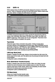
... the data transfer mode. These values are specifically configuring a CD-ROM drive. Configuration options: [Disabled] [Auto] PIO Mode [Auto] Allows you are not user-configurable. The BIOS automatically detects the values opposite the dimmed items (Device, Vendor, Size, LBA Mode, Block Mode, PIO Mode, Async DMA, Ultra DMA, and SMART monitoring). Type [Auto] Selects the type of Serial ATA devices. Select [ARMD] (ATAPI Removable Media Device) if your device is a separate sub-menu for each SATA device. When set to [Disabled], the data transfer...
... the data transfer mode. These values are specifically configuring a CD-ROM drive. Configuration options: [Disabled] [Auto] PIO Mode [Auto] Allows you are not user-configurable. The BIOS automatically detects the values opposite the dimmed items (Device, Vendor, Size, LBA Mode, Block Mode, PIO Mode, Async DMA, Ultra DMA, and SMART monitoring). Type [Auto] Selects the type of Serial ATA devices. Select [ARMD] (ATAPI Removable Media Device) if your device is a separate sub-menu for each SATA device. When set to [Disabled], the data transfer...
User Manual
Page 82
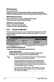
Configuration options: [IDE] [RAID] [AHCI] • If you want to use the Advanced Host Controller Interface (AHCI), set this item to [RAID]. 3-14 Chapter 3: BIOS setup Select an item then press if you want the Serial ATA hard disk drives to use the Serial ATA hard disk drives as [IDE] Sets the configuration for the SATA devices installed in this menu allow you to set or change the configurations for the Serial ATA connectors supported by allowing the drive to internally optimize the order of commands. •...
Configuration options: [IDE] [RAID] [AHCI] • If you want to use the Advanced Host Controller Interface (AHCI), set this item to [RAID]. 3-14 Chapter 3: BIOS setup Select an item then press if you want the Serial ATA hard disk drives to use the Serial ATA hard disk drives as [IDE] Sets the configuration for the SATA devices installed in this menu allow you to set or change the configurations for the Serial ATA connectors supported by allowing the drive to internally optimize the order of commands. •...

User Manual
Page 85
...ASUS P6T 3-17 Select either one of CPU overclocking options to Sub Screen +- is enabled BLCK frequency, CPU ratio and memory parameters will be auto optimized. BIOS SETUP UTILITY Main Ai Tweaker Advanced Power Boot Tools Exit Configure System Performance Settings Ai Overclock Tuner CPU Ratio Setting Intel(R) SpeedStep(TM) Tech Intel(R) Turbo Mode Tech DRAM Frequency [Auto] [Auto] [Enabled] [Enabled] [Auto] DRAM Timing Control ******* Please key in numbers directly! ******* CPU Voltage [Auto] CPU PLL Voltage [Auto] QPI/DRAM Core...
...ASUS P6T 3-17 Select either one of CPU overclocking options to Sub Screen +- is enabled BLCK frequency, CPU ratio and memory parameters will be auto optimized. BIOS SETUP UTILITY Main Ai Tweaker Advanced Power Boot Tools Exit Configure System Performance Settings Ai Overclock Tuner CPU Ratio Setting Intel(R) SpeedStep(TM) Tech Intel(R) Turbo Mode Tech DRAM Frequency [Auto] [Auto] [Enabled] [Enabled] [Auto] DRAM Timing Control ******* Please key in numbers directly! ******* CPU Voltage [Auto] CPU PLL Voltage [Auto] QPI/DRAM Core...
User Manual
Page 93
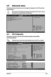
... Item Enter Go to change the settings for the CPU and other system devices. BIOS SETUP UTILITY Advanced Configure advanced CPU settings Module Version:3F.11 Manufacturer:Intel Brand String:Genuine Intel(R) CPU @ 2.67GHz Frequency :2.68GHz BCLK Speed :133MHz Cache L1 :128 KB Cache L2 :1024 KB Cache L3 :8192 KB Ratio Status:Unlocked (Min:12, Max:20) Ratio Actual Value :20 CPUID :106A2 CPU Ratio Setting [Auto] C1E Support [Enabled...
... Item Enter Go to change the settings for the CPU and other system devices. BIOS SETUP UTILITY Advanced Configure advanced CPU settings Module Version:3F.11 Manufacturer:Intel Brand String:Genuine Intel(R) CPU @ 2.67GHz Frequency :2.68GHz BCLK Speed :133MHz Cache L1 :128 KB Cache L2 :1024 KB Cache L3 :8192 KB Ratio Status:Unlocked (Min:12, Max:20) Ratio Actual Value :20 CPUID :106A2 CPU Ratio Setting [Auto] C1E Support [Enabled...
User Manual
Page 97
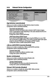
...your VGA card, set this item to enable or disable the High Definition Audio Controller. Configuration options: [Enabled] [Disabled] LAN Boot ROM [Disabled] This item appears only when you to [HDMI Output]. 3.5.3 Onboard Device Configuration BIOS SETUP UTILITY Advanced Onboard Devices Configuration High Definition Audio [Enabled] Front Panel Type [HD Audio] SPDIF Mode Setting [SPDIF Output] J-Micron eSATA/PATA Controller [Enabled] Controller Mode [IDE] Realtek LAN [Enabled] LAN Boot ROM [Disabled] Onboard 1394 Controller [Enabled] Options Enabled...
...your VGA card, set this item to enable or disable the High Definition Audio Controller. Configuration options: [Enabled] [Disabled] LAN Boot ROM [Disabled] This item appears only when you to [HDMI Output]. 3.5.3 Onboard Device Configuration BIOS SETUP UTILITY Advanced Onboard Devices Configuration High Definition Audio [Enabled] Front Panel Type [HD Audio] SPDIF Mode Setting [SPDIF Output] J-Micron eSATA/PATA Controller [Enabled] Controller Mode [IDE] Realtek LAN [Enabled] LAN Boot ROM [Disabled] Onboard 1394 Controller [Enabled] Options Enabled...
User Manual
Page 99
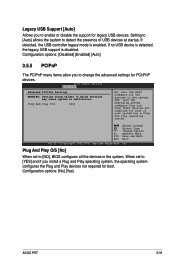
... USB controller legacy mode is disabled. Plug And Play O/S [No] NO: lets the BIOS configure all the devices in the system. BIOS SETUP UTILITY Advanced Advanced PCI/PnP Settings WARNING: Setting wrong values in below sections may cause system to enable or disable the support for PCI/PnP devices. Plug And Play O/S [No] When set to [YES] and if you to change the advanced settings for legacy USB devices. If no USB device is detected, the legacy USB support is enabled. Configuration options: [No] [Yes] ASUS P6T...
... USB controller legacy mode is disabled. Plug And Play O/S [No] NO: lets the BIOS configure all the devices in the system. BIOS SETUP UTILITY Advanced Advanced PCI/PnP Settings WARNING: Setting wrong values in below sections may cause system to enable or disable the support for PCI/PnP devices. Plug And Play O/S [No] When set to [YES] and if you to change the advanced settings for legacy USB devices. If no USB device is detected, the legacy USB support is enabled. Configuration options: [No] [Yes] ASUS P6T...

User Manual
Page 100
... Interrupt Controller (APIC). When set to be used for the Advanced Power Management (APM). BIOS SETUP UTILITY Main Ai Tweaker Advanced Power Boot Tools Exit Suspend Mode Repost Video on S3 Resume ACPI 2.0 Support ACPI APIC Support [Auto] [No] [Disabled] [Enabled] Select the ACPI state used for system suspend. Configuration options: [No] [Yes] 3.6.3 ACPI 2.0 Support [Disabled] Add additional tables as per ACPI 2.0 specifications. Configuration options: [Disabled] [Enabled] 3.6.4 ACPI APIC Support [Enabled] Allows you to display the configuration options...
... Interrupt Controller (APIC). When set to be used for the Advanced Power Management (APM). BIOS SETUP UTILITY Main Ai Tweaker Advanced Power Boot Tools Exit Suspend Mode Repost Video on S3 Resume ACPI 2.0 Support ACPI APIC Support [Auto] [No] [Disabled] [Enabled] Select the ACPI state used for system suspend. Configuration options: [No] [Yes] 3.6.3 ACPI 2.0 Support [Disabled] Add additional tables as per ACPI 2.0 specifications. Configuration options: [Disabled] [Enabled] 3.6.4 ACPI APIC Support [Enabled] Allows you to display the configuration options...

User Manual
Page 106
...Clock (RTC) RAM. To clear the supervisor password, select the Change Supervisor Password then press . See section 2.6 Jumpers for information on top of at least six letters and/or numbers, then press . 3. 3.7.3 Security The Security menu items allow you set a password, this item to disabled password. BIOS SETUP UTILITY Boot Security Settings Supervisor Password : Not Installed User Password : Not Installed Change Supervisor Password Change User Password to change the supervisor password. again to set a Supervisor Password: 1. Select Screen Select Item Enter Change...
...Clock (RTC) RAM. To clear the supervisor password, select the Change Supervisor Password then press . See section 2.6 Jumpers for information on top of at least six letters and/or numbers, then press . 3. 3.7.3 Security The Security menu items allow you set a password, this item to disabled password. BIOS SETUP UTILITY Boot Security Settings Supervisor Password : Not Installed User Password : Not Installed Change Supervisor Password Change User Password to change the supervisor password. again to set a Supervisor Password: 1. Select Screen Select Item Enter Change...

User Manual
Page 152
... chapter 2 for details. • ASUS Express Gate supports HDDs or ODDs connected to zero (0); Installing ASUS Express Gate • ASUS Express Gate supports installation on your motherboard user manual for the exact location of onboard SATA ports. • ASUS Express Gate requires a minimum screen resolution of powering on the computer. 4-36 Click any of BIOS setup in IDE or SATA mode only. The First Screen Express Gate's first screen appears within a few seconds of 1024 x 768. The Drivers installation tab appears if your...
... chapter 2 for details. • ASUS Express Gate supports HDDs or ODDs connected to zero (0); Installing ASUS Express Gate • ASUS Express Gate supports installation on your motherboard user manual for the exact location of onboard SATA ports. • ASUS Express Gate requires a minimum screen resolution of powering on the computer. 4-36 Click any of BIOS setup in IDE or SATA mode only. The First Screen Express Gate's first screen appears within a few seconds of 1024 x 768. The Drivers installation tab appears if your...

User Manual
Page 155
... (which is connected. Then enter the user name and password of using Express Gate, or if Internet doesn't seem to be unchecked and grayed out. To configure network settings 1. If you computer automatically obtains network settings via DHCP, you have to click Setup for the WiFi option. If your wireless access point has security enabled, select the corresponding security algorithm from the drop-down list (e.g. ASUS P6T 4-39...
... (which is connected. Then enter the user name and password of using Express Gate, or if Internet doesn't seem to be unchecked and grayed out. To configure network settings 1. If you computer automatically obtains network settings via DHCP, you have to click Setup for the WiFi option. If your wireless access point has security enabled, select the corresponding security algorithm from the drop-down list (e.g. ASUS P6T 4-39...

User Manual
Page 164
... a RAID set(s). Enter the BIOS Setup during POST. 2. Select the item Configure SATA as item options, then press . 5. For optimal performance, install identical drives of the same model and capacity when creating a disk array. Refer to the power connector on entering and navigating through the Intel® ICH10R Southbridge chip. Connect a SATA power cable to the system or the motherboard user guide for details on each drive. 4.4.3 Intel® RAID configurations This motherboard supports RAID 0, RAID 1, RAID 5, RAID 10 and Intel® Matrix Storage configurations...
... a RAID set(s). Enter the BIOS Setup during POST. 2. Select the item Configure SATA as item options, then press . 5. For optimal performance, install identical drives of the same model and capacity when creating a disk array. Refer to the power connector on entering and navigating through the Intel® ICH10R Southbridge chip. Connect a SATA power cable to the system or the motherboard user guide for details on each drive. 4.4.3 Intel® RAID configurations This motherboard supports RAID 0, RAID 1, RAID 5, RAID 10 and Intel® Matrix Storage configurations...


