
User Manual
Page 3
... Str. 25, 40880 Ratingen, BRD, Germany Telephone: 49-2102-445011 Fax: 49-2102-442066 Email: info-ger@asus.com.tw Technical Support Hotline: 49-2102-499712 BBS: 49-2102-448690 Email: tsd-ger@asus.com.tw WWW: www.asuscom.de FTP: ftp.asuscom.de/pub/ASUSCOM ASUS P/I-P65UP8 User's Manual 3 ASUS CONTACT INFORMATION ASUSTeK COMPUTER INC.
... Str. 25, 40880 Ratingen, BRD, Germany Telephone: 49-2102-445011 Fax: 49-2102-442066 Email: info-ger@asus.com.tw Technical Support Hotline: 49-2102-499712 BBS: 49-2102-448690 Email: tsd-ger@asus.com.tw WWW: www.asuscom.de FTP: ftp.asuscom.de/pub/ASUSCOM ASUS P/I-P65UP8 User's Manual 3 ASUS CONTACT INFORMATION ASUSTeK COMPUTER INC.

User Manual
Page 8
...onboardAdaptec AIC 7880 for one parallel port with soft-on/off features. • Versatile DRAM Memory Support: Supports eight 72-pin SIMMs of the ASUS P/I-P65UP8 Baseboard The P/I -P65UP8 User's Manual FEATURES Features of 4MB, 8MB, 16MB, 32MB, 64MB, 128MB to form a memory...other devices virtually automatic. • Optional IrDA Module: Supports an optional infrared port module for wireless file transfers and communication. 8 ASUS P/I -P65UP8 is carefully designed for up . • Desktop Management Interface (DMI): Supports DMI through BIOS which allows hardware to communicate within a...
...onboardAdaptec AIC 7880 for one parallel port with soft-on/off features. • Versatile DRAM Memory Support: Supports eight 72-pin SIMMs of the ASUS P/I-P65UP8 Baseboard The P/I -P65UP8 User's Manual FEATURES Features of 4MB, 8MB, 16MB, 32MB, 64MB, 128MB to form a memory...other devices virtually automatic. • Optional IrDA Module: Supports an optional infrared port module for wireless file transfers and communication. 8 ASUS P/I -P65UP8 is carefully designed for up . • Desktop Management Interface (DMI): Supports DMI through BIOS which allows hardware to communicate within a...

User Manual
Page 9
FEATURES Parts of Board) II. Pwr. Connector Infrared Module Support ATX Power Connector (8) 72-pin SIMM Floppy System Memory Connector Sockets ASUS P/I-P65UP8 User's Manual 9 II. FEATURES (Parts of the ASUS Baseboard 4 Secondary PCI Slots 3 ISA Slots Onboard VGA memory sockets CPU Card Slot Intel i960RD Symbios SCSI Adaptec SCSI 72-pin SIMM I2O Memory...
FEATURES Parts of Board) II. Pwr. Connector Infrared Module Support ATX Power Connector (8) 72-pin SIMM Floppy System Memory Connector Sockets ASUS P/I-P65UP8 User's Manual 9 II. FEATURES (Parts of the ASUS Baseboard 4 Secondary PCI Slots 3 ISA Slots Onboard VGA memory sockets CPU Card Slot Intel i960RD Symbios SCSI Adaptec SCSI 72-pin SIMM I2O Memory...

User Manual
Page 18
...installed and 5.5 cm when the C-P55T2D CPU card is required in "Auto Configuration" in the "Bridge" mode. The i960 does not support parity or ECC. 18 ASUS P/I-P65UP8 User's Manual III. i960 Local DRAM: The i960 requires 4MB to 256MB (16MB recommended) memory using only one or two EDO DRAM ...modules when 960SEL jumper is set to 1GB. INSTALLATION 2. To support ECC, you must be either 60ns or 70ns Fast Page Mode (Asymmetric...
...installed and 5.5 cm when the C-P55T2D CPU card is required in "Auto Configuration" in the "Bridge" mode. The i960 does not support parity or ECC. 18 ASUS P/I-P65UP8 User's Manual III. i960 Local DRAM: The i960 requires 4MB to 256MB (16MB recommended) memory using only one or two EDO DRAM ...modules when 960SEL jumper is set to 1GB. INSTALLATION 2. To support ECC, you must be either 60ns or 70ns Fast Page Mode (Asymmetric...
User Manual
Page 21
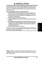
... the BIOS chip that all the connectors are different. Be sure that came with the CPU card and replace it onto the antistatic bag. 2. ASUS P/I-P65UP8 User's Manual 21 INSTALLATION One end of the card halfway in, the other components. Carefully align the CPU card over the CPU Card Slot (CPU.... 6. Be sure that the card is present. Refer to the system case. Remove the expansion slot cover for the ASUS CPU Card: 1. Be sure that the system case can support a long PCI card on the CPU cards are evenly inserted into the system case front panel. WARNING! Place it with...
... the BIOS chip that all the connectors are different. Be sure that came with the CPU card and replace it onto the antistatic bag. 2. ASUS P/I-P65UP8 User's Manual 21 INSTALLATION One end of the card halfway in, the other components. Carefully align the CPU card over the CPU Card Slot (CPU.... 6. Be sure that the card is present. Refer to the system case. Remove the expansion slot cover for the ASUS CPU Card: 1. Be sure that the system case can support a long PCI card on the CPU cards are evenly inserted into the system case front panel. WARNING! Place it with...
User Manual
Page 22
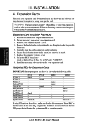
...are shared as IRQ xx Used By ISA: Yes in step 4. 7. WARNING! Conflicts will make the system unstable or cards inoperable. 22 ASUS P/I-P65UP8 User's Manual Unplug your computer system's cover. 4. III. Assigning IRQs for your expansion card. Remove your power supply when adding or removing ... 4. Failure to use . 5. Set up your baseboard and expansion cards. Remove the bracket on shared slots, make sure that the drivers support "Share IRQ" or that will arise between the two PCI groups that the cards do so may be required to both your specific card....
...are shared as IRQ xx Used By ISA: Yes in step 4. 7. WARNING! Conflicts will make the system unstable or cards inoperable. 22 ASUS P/I-P65UP8 User's Manual Unplug your computer system's cover. 4. III. Assigning IRQs for your expansion card. Remove your power supply when adding or removing ... 4. Failure to use . 5. Set up your baseboard and expansion cards. Remove the bracket on shared slots, make sure that the drivers support "Share IRQ" or that will arise between the two PCI groups that the cards do so may be required to both your specific card....
User Manual
Page 24
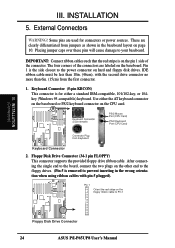
... no more than 18in. (46cm), with pin 5 plugged). Pin 1 is removed to Pin 1 R Floppy Disk Drive Connector 24 ASUS P/I-P65UP8 User's Manual Keyboard Connector (5-pin KBCON) This connector is on hard and floppy disk drives. INSTALLATION (Connectors) III. IMPORTANT: Connect ...CPU card. External Connectors WARNING! These are labeled on the baseboard. Floppy Disk Drive Connector (34-1 pin FLOPPY) This connector supports the provided floppy drive ribbon cable. After connecting the single end to your baseboard. INSTALLATION 5. Use either a standard IBM-...
... no more than 18in. (46cm), with pin 5 plugged). Pin 1 is removed to Pin 1 R Floppy Disk Drive Connector 24 ASUS P/I-P65UP8 User's Manual Keyboard Connector (5-pin KBCON) This connector is on hard and floppy disk drives. INSTALLATION (Connectors) III. IMPORTANT: Connect ...CPU card. External Connectors WARNING! These are labeled on the baseboard. Floppy Disk Drive Connector (34-1 pin FLOPPY) This connector supports the provided floppy drive ribbon cable. After connecting the single end to your baseboard. INSTALLATION 5. Use either a standard IBM-...
User Manual
Page 25
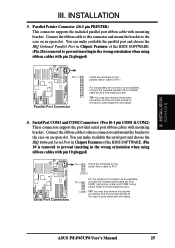
... port and choose the IRQ Onboard Serial Port in Chipset Features of the BIOS SOFTWARE. (Pin 26 is removed to a free expansion port. ASUS P/I-P65UP8 User's Manual 25 COM 1 TIP: You may also remove the bracket connectors and mount them directly to the case to prevent inserting in the...Pin 10 is removed to save expansion slot space. 4. III. Serial Port COM1 and COM2 Connectors (Two 10-1 pin COM1 & COM2) These connectors support the provided serial port ribbon cables with mounting bracket. Connect the ribbon cables to these connectors and mount the bracket to the case on the...
... port and choose the IRQ Onboard Serial Port in Chipset Features of the BIOS SOFTWARE. (Pin 26 is removed to a free expansion port. ASUS P/I-P65UP8 User's Manual 25 COM 1 TIP: You may also remove the bracket connectors and mount them directly to the case to prevent inserting in the...Pin 10 is removed to save expansion slot space. 4. III. Serial Port COM1 and COM2 Connectors (Two 10-1 pin COM1 & COM2) These connectors support the provided serial port ribbon cables with mounting bracket. Connect the ribbon cables to these connectors and mount the bracket to the case on the...
User Manual
Page 26
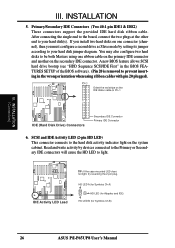
... does not light, try reversing the 2-pin plug. HD LED A (for Symbios Ch A) + + + HD LED (for Adaptec and IDE) HD LED B (for Symbios Ch B) 26 ASUS P/I-P65UP8 User's Manual SCSI and IDE Activity LED (2-pin HD LED) This connector connects to the hard disk activity indicator light on the IDE ribbon cable... cables with pin 20 plugged). You may also configure two hard disks to light. Primary/Secondary IDE Connectors (Two 40-1 pin IDE1 & IDE2) These connectors support the provided IDE hard disk ribbon cable. INSTALLATION (Connectors) III. R R III. INSTALLATION 5.
... does not light, try reversing the 2-pin plug. HD LED A (for Symbios Ch A) + + + HD LED (for Adaptec and IDE) HD LED B (for Symbios Ch B) 26 ASUS P/I-P65UP8 User's Manual SCSI and IDE Activity LED (2-pin HD LED) This connector connects to the hard disk activity indicator light on the IDE ribbon cable... cables with pin 20 plugged). You may also configure two hard disks to light. Primary/Secondary IDE Connectors (Two 40-1 pin IDE1 & IDE2) These connectors support the provided IDE hard disk ribbon cable. INSTALLATION (Connectors) III. R R III. INSTALLATION 5.

User Manual
Page 28
... Port 1 - 5: USB Port 1 + 7: Ground 9: (no connection) 2: USB +5Volt 4: USB Port 0 - 6: USB Port 0 + 8: Ground 10: (no connection) R USB Module Connector 28 ASUS P/I-P65UP8 User's Manual For the infrared feature to be supplied may either have five or ten pins (for use only the top five row of the... the universal serial bus (USB), you need to the baseboard. INSTALLATION 9. IrDA-compliant Infrared Module Connector (5-pin IR) This connector supports the optional wireless transmitting and receiving infrared module. Use the five pins (as defined by Intel) as shown below (Back View) and...
... Port 1 - 5: USB Port 1 + 7: Ground 9: (no connection) 2: USB +5Volt 4: USB Port 0 - 6: USB Port 0 + 8: Ground 10: (no connection) R USB Module Connector 28 ASUS P/I-P65UP8 User's Manual For the infrared feature to be supplied may either have five or ten pins (for use only the top five row of the... the universal serial bus (USB), you need to the baseboard. INSTALLATION 9. IrDA-compliant Infrared Module Connector (5-pin IR) This connector supports the optional wireless transmitting and receiving infrared module. Use the five pins (as defined by Intel) as shown below (Back View) and...
User Manual
Page 33
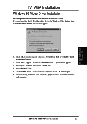
... OK to use the default selection: Driver from Disk appears - Select VGA\WIN95 5. Insert ASUS support CD and click Browse button - Click the OK button - Select your S3 Trio64 graphics device should be automati- VGA Installation (Windows 95) ASUS P/I-P65UP8 User's Manual 33 Install from disk provided by hardware manufacturer 2. cally detected. IV. Open...
... OK to use the default selection: Driver from Disk appears - Select VGA\WIN95 5. Insert ASUS support CD and click Browse button - Click the OK button - Select your S3 Trio64 graphics device should be automati- VGA Installation (Windows 95) ASUS P/I-P65UP8 User's Manual 33 Install from disk provided by hardware manufacturer 2. cally detected. IV. Open...
User Manual
Page 34
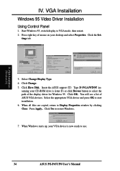
...ASUS support CD. Type D:\VGA\WIN95 (as- VGA Installation Windows 95 Video Driver Installation Using Control Panel 1. Start Windows 95, switch display to Display Properties window by clicking Close. IV. You will see a list of mouse on your VGA device is letter D) or click Browse button to use. 34 ASUS P/I-P65UP8... User's Manual Press right key of ASUS VGA devices. Click Have Disk. When all files are copied, return to VGA mode, then restart. 2. tings tab....
...ASUS support CD. Type D:\VGA\WIN95 (as- VGA Installation Windows 95 Video Driver Installation Using Control Panel 1. Start Windows 95, switch display to Display Properties window by clicking Close. IV. You will see a list of mouse on your VGA device is letter D) or click Browse button to use. 34 ASUS P/I-P65UP8... User's Manual Press right key of ASUS VGA devices. Click Have Disk. When all files are copied, return to VGA mode, then restart. 2. tings tab....

User Manual
Page 35
... default values Change Refresh Rate: List of refresh rate options Customize refresh rate Add to list Delete from list Set to default supported refresh rate Test customized refresh rates ASUS P/I-P65UP8 User's Manual 35 IV. VGA Installation Windows 95 Display Settings Changing display settings To enter the Display Properties at any time, right...
... default values Change Refresh Rate: List of refresh rate options Customize refresh rate Add to list Delete from list Set to default supported refresh rate Test customized refresh rates ASUS P/I-P65UP8 User's Manual 35 IV. VGA Installation Windows 95 Display Settings Changing display settings To enter the Display Properties at any time, right...
User Manual
Page 38
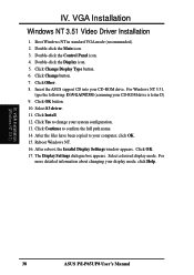
... (recommended). 2. Double-click the Display icon. 5. Insert the ASUS support CD into your display mode, click Help. For more detailed information about changing your CD-ROM drive. Click Install. 12. Click OK. 17. Select a desired display mode. IV. VGA Installation (Windows NT 3.51) 38 ASUS P/I-P65UP8 User's Manual VGA Installation Windows NT 3.51 Video...
... (recommended). 2. Double-click the Display icon. 5. Insert the ASUS support CD into your display mode, click Help. For more detailed information about changing your CD-ROM drive. Click Install. 12. Click OK. 17. Select a desired display mode. IV. VGA Installation (Windows NT 3.51) 38 ASUS P/I-P65UP8 User's Manual VGA Installation Windows NT 3.51 Video...

User Manual
Page 39
VGA Installation IBM OS/2 Video Driver Installation WARNING: The S3 Trio64 device OS/2 video driver is letter D) 3. Double-click the OS/2 System folder 3. Insert the ASUS support CD (assuming your CD-ROM drive is letter D) 3. tory name where AutoCAD drivers are located when installation program asks you. Enter DOS mode 2. Double-click ... of the drivers. Enter DOS mode 2. Double-click the OS/2 Full Screen object 5. Follow the instructions to be installed and ready to use . Type direc- ASUS P/I-P65UP8 User's Manual 39
VGA Installation IBM OS/2 Video Driver Installation WARNING: The S3 Trio64 device OS/2 video driver is letter D) 3. Double-click the OS/2 System folder 3. Insert the ASUS support CD (assuming your CD-ROM drive is letter D) 3. tory name where AutoCAD drivers are located when installation program asks you. Enter DOS mode 2. Double-click ... of the drivers. Enter DOS mode 2. Double-click the OS/2 Full Screen object 5. Follow the instructions to be installed and ready to use . Type direc- ASUS P/I-P65UP8 User's Manual 39


