User Manual
Page 4
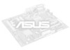
... Devices 29 Terminator Settings for the ASUS PCI-SC860 30 Terminator Settings for the ASUS PCI-SC200 30 SCSI ID Numbers for ISA Cards 21 5. Central Processing Unit 18 System Case 18 4. CONTENTS I -P65UP5 Baseboard 8 II. INSTALLATION 10 ASUS Baseboard Layout 10 Installation Steps 12 1. External Connectors 22 IV. INTRODUCTION 7 How this Manual is Organized 7 Item Checklist 7 Features of the ASUS Baseboard 9 III. FEATURES 8 Parts of the ASUS P/I . ASUS I-A16C Audio Card...
... Devices 29 Terminator Settings for the ASUS PCI-SC860 30 Terminator Settings for the ASUS PCI-SC200 30 SCSI ID Numbers for ISA Cards 21 5. Central Processing Unit 18 System Case 18 4. CONTENTS I -P65UP5 Baseboard 8 II. INSTALLATION 10 ASUS Baseboard Layout 10 Installation Steps 12 1. External Connectors 22 IV. INTRODUCTION 7 How this Manual is Organized 7 Item Checklist 7 Features of the ASUS Baseboard 9 III. FEATURES 8 Parts of the ASUS P/I . ASUS I-A16C Audio Card...
User Manual
Page 6
...device may cause undesired operation. The use of shielded cables for connection of the monitor to the graphics card is required to radio communications. However, there is connected. • Consult the dealer or an experienced radio/TV technician for help. These limits are designed to which can radiate radio frequency energy and, if not installed and used in a particular installation...6 ASUS P/I-P65UP5 User's Manual FCC & DOC COMPLIANCE Federal Communications Commission Statement This device complies with the limits for a Class B digital device, pursuant to Part 15 of the FCC ...
...device may cause undesired operation. The use of shielded cables for connection of the monitor to the graphics card is required to radio communications. However, there is connected. • Consult the dealer or an experienced radio/TV technician for help. These limits are designed to which can radiate radio frequency energy and, if not installed and used in a particular installation...6 ASUS P/I-P65UP5 User's Manual FCC & DOC COMPLIANCE Federal Communications Commission Statement This device complies with the limits for a Class B digital device, pursuant to Part 15 of the FCC ...
User Manual
Page 7
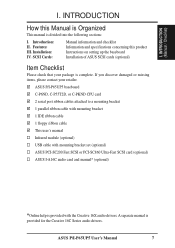
..., C-P55T2D, or C-PKND CPU card 2 serial port ribbon cables attached to a mounting bracket 1 parallel ribbon cable with mounting bracket 1 IDE ribbon cable 1 floppy ribbon cable This user's manual Infrared module (optional) USB cable with the Creative 16X audio drivers. Introduction: II. Installation: IV. If you discover damaged or missing items, please contact your package is divided into the following sections: I . I -P65UP5 User's Manual 7 ASUS P/I . INTRODUCTION (Manual / Checklist) I . Features: III. INTRODUCTION How this product Instructions on setting...
..., C-P55T2D, or C-PKND CPU card 2 serial port ribbon cables attached to a mounting bracket 1 parallel ribbon cable with mounting bracket 1 IDE ribbon cable 1 floppy ribbon cable This user's manual Infrared module (optional) USB cable with the Creative 16X audio drivers. Introduction: II. Installation: IV. If you discover damaged or missing items, please contact your package is divided into the following sections: I . I -P65UP5 User's Manual 7 ASUS P/I . INTRODUCTION (Manual / Checklist) I . Features: III. INTRODUCTION How this product Instructions on setting...
User Manual
Page 8
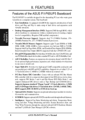
... hardware to communicate within a standard protocol creating a higher level of compatibility. (Requires DMI-enabled components.) • Versatile Processor Support: Supports dual 75-233MHz Pentium, 150- 200MHz Pentium Pro, 233-333MHz Pentium II processors. • Versatile DRAM Memory Support: Supports eight 72-pin SIMMs of hard drives and expansion cards virtually automatic. • Desktop Management Interface (DMI): Supports DMI through the optional onboard LM78 Hardware Monitor and Intel® LANDesk Client Manager (LDCM) software. 8 ASUS P/I-P65UP5 User's Manual
... hardware to communicate within a standard protocol creating a higher level of compatibility. (Requires DMI-enabled components.) • Versatile Processor Support: Supports dual 75-233MHz Pentium, 150- 200MHz Pentium Pro, 233-333MHz Pentium II processors. • Versatile DRAM Memory Support: Supports eight 72-pin SIMMs of hard drives and expansion cards virtually automatic. • Desktop Management Interface (DMI): Supports DMI through the optional onboard LM78 Hardware Monitor and Intel® LANDesk Client Manager (LDCM) software. 8 ASUS P/I-P65UP5 User's Manual
User Manual
Page 10
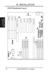
... Connector JP9 Battery Test Chassis Conn. INSTALLATION ASUS Baseboard Layout Serial Ports Parallel Port COM 1 COM 2 Board Power Input P9 P8 Floppy Drives Secondary IDE Primary IDE FANPWR1 CPU Card Slot SIMM Socket 7 (Bank 3) SIMM Socket 5 (Bank 2) SIMM Socket 3 (Bank 1) SIMM Socket 1 (Bank 0) FANPWR2 CPU Card Slot PCI Slot 1 Multi-i/O Enable/Disable PCI Slot 2 PCI Slot 3 PCI Slot 4 SIMM Socket 8 (Bank 3) BUS Freq. INSTALLATION (Board Layout) ASUS P/I-P65UP5 User's Manual The items in outline are only available on the baseboard with onboard LM78 Hardware Monitor. Keyboard...
... Connector JP9 Battery Test Chassis Conn. INSTALLATION ASUS Baseboard Layout Serial Ports Parallel Port COM 1 COM 2 Board Power Input P9 P8 Floppy Drives Secondary IDE Primary IDE FANPWR1 CPU Card Slot SIMM Socket 7 (Bank 3) SIMM Socket 5 (Bank 2) SIMM Socket 3 (Bank 1) SIMM Socket 1 (Bank 0) FANPWR2 CPU Card Slot PCI Slot 1 Multi-i/O Enable/Disable PCI Slot 2 PCI Slot 3 PCI Slot 4 SIMM Socket 8 (Bank 3) BUS Freq. INSTALLATION (Board Layout) ASUS P/I-P65UP5 User's Manual The items in outline are only available on the baseboard with onboard LM78 Hardware Monitor. Keyboard...
User Manual
Page 11
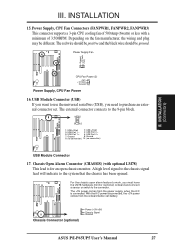
... TB LED (CON1) p. 26 Turbo LED Lead (2 pins) 10) SMI (CON1) p. 26 SMI Suspend Switch Lead (2 pins) 11) RESET (CON1) p. 26 Reset Switch Lead (2 pins) 12) PWR LED (CON1) p. 26 System Power LED Lead (3 pins) 13) KEYLOCK (CON1) p. 26 Keyboard Lock Switch Lead (2 pins) 14) SPEAKER (CON1) p. 26 Speaker Output Connector (4 pins) 15) FANPWR1,FANPWR2,FANPWR3 p. 27 Power Supply, CPU Fan Power Connectors 16) USB p. 27 USB Module Connector (18-pin block) 17) CHASSIS (optional) p. 27 Chassis Open Alarm Connector (3-pin block) ASUS P/I-P65UP5 User's Manual 11 INSTALLATION (Board Layout...
... TB LED (CON1) p. 26 Turbo LED Lead (2 pins) 10) SMI (CON1) p. 26 SMI Suspend Switch Lead (2 pins) 11) RESET (CON1) p. 26 Reset Switch Lead (2 pins) 12) PWR LED (CON1) p. 26 System Power LED Lead (3 pins) 13) KEYLOCK (CON1) p. 26 Keyboard Lock Switch Lead (2 pins) 14) SPEAKER (CON1) p. 26 Speaker Output Connector (4 pins) 15) FANPWR1,FANPWR2,FANPWR3 p. 27 Power Supply, CPU Fan Power Connectors 16) USB p. 27 USB Module Connector (18-pin block) 17) CHASSIS (optional) p. 27 Chassis Open Alarm Connector (3-pin block) ASUS P/I-P65UP5 User's Manual 11 INSTALLATION (Board Layout...
User Manual
Page 12
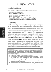
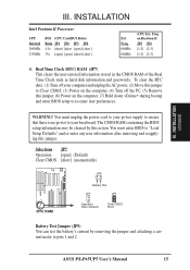
... to connect pins 1&2 and to connect jumper pins (JP) on the board. Jumpers Several hardware settings are separated from other components. 4. Jumpers with three pins. Computer motherboards, baseboards and components, such as diagramed. INSTALLATION Installation Steps Before using your computer when working on jumpers with two pins will also be - The jumpers will be sharing pins from the system. 12 ASUS P/I-P65UP5 User's Manual INSTALLATION (Jumpers) III. Install the Central Processing Unit (CPU) Card 4. Setup the BIOS Software (see the CPU Card BIOS section...
... to connect pins 1&2 and to connect jumper pins (JP) on the board. Jumpers Several hardware settings are separated from other components. 4. Jumpers with three pins. Computer motherboards, baseboards and components, such as diagramed. INSTALLATION Installation Steps Before using your computer when working on jumpers with two pins will also be - The jumpers will be sharing pins from the system. 12 ASUS P/I-P65UP5 User's Manual INSTALLATION (Jumpers) III. Install the Central Processing Unit (CPU) Card 4. Setup the BIOS Software (see the CPU Card BIOS section...
User Manual
Page 15
... jumper. Freq on the computer, (7) Hold down during bootup and enter BIOS setup to pins 1 and 2. You must enter BIOS to your baseboard. Real Time Clock (RTC) RAM (JP7) This clears the user-entered information stored in the CMOS RAM of the Real Time Clock such as hard disk information and passwords. To clear the RTC data: (1) Turn off your power supply to ensure that there is no power to "Load Setup Defaults" and re-enter any user...
... jumper. Freq on the computer, (7) Hold down during bootup and enter BIOS setup to pins 1 and 2. You must enter BIOS to your baseboard. Real Time Clock (RTC) RAM (JP7) This clears the user-entered information stored in the CMOS RAM of the Real Time Clock such as hard disk information and passwords. To clear the RTC data: (1) Turn off your power supply to ensure that there is no power to "Load Setup Defaults" and re-enter any user...
User Manual
Page 16
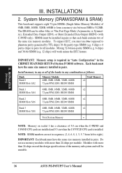
... System Memory = NOTE: Memory on socket 1 has a clearance of Section IV BIOS software. INSTALLATION 2. Do not use true (opposed to 512MB. To support ECC, you must have the same size memory installed in the CHIPSET FEATURES SETUP of 5.0 cm when the C-PKND and C-P6ND CPU cards are not in sequence, (2, 4, 6, 8, 1, 3, 5, 7 from left to right.) IMPORTANT: Each bank must use memory modules with C-P6ND only). III. INSTALLATION (Memory) III. System Memory (DRAM...
... System Memory = NOTE: Memory on socket 1 has a clearance of Section IV BIOS software. INSTALLATION 2. Do not use true (opposed to 512MB. To support ECC, you must have the same size memory installed in the CHIPSET FEATURES SETUP of 5.0 cm when the C-PKND and C-P6ND CPU cards are not in sequence, (2, 4, 6, 8, 1, 3, 5, 7 from left to right.) IMPORTANT: Each bank must use memory modules with C-P6ND only). III. INSTALLATION (Memory) III. System Memory (DRAM...
User Manual
Page 17
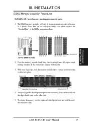
ASUS P/I-P65UP5 User's Manual 17 Press the memory module firmly into place starting from a 45 degree angle making sure that it clicks into a vertical position so that all the contacts are aligned with the slot. 3. Support Clip 72 Pin DRAM in symmetric pairs. 1. The SIMM memory modules... on one end of the SIMM slots which requires the "Notched End" of the clips. INSTALLATION DRAM Memory Installation Procedures IMPORTANT: Install memory modules in SIMM Socket Safety Tab (This Side Only) Mounting Hole 4. INSTALLATION (DRAM Memory) R 72-Pin SIMM Sockets B0 B1 B2 B3 B0 B1 ...
ASUS P/I-P65UP5 User's Manual 17 Press the memory module firmly into place starting from a 45 degree angle making sure that it clicks into a vertical position so that all the contacts are aligned with the slot. 3. Support Clip 72 Pin DRAM in symmetric pairs. 1. The SIMM memory modules... on one end of the SIMM slots which requires the "Notched End" of the clips. INSTALLATION DRAM Memory Installation Procedures IMPORTANT: Install memory modules in SIMM Socket Safety Tab (This Side Only) Mounting Hole 4. INSTALLATION (DRAM Memory) R 72-Pin SIMM Sockets B0 B1 B2 B3 B0 B1 ...
User Manual
Page 19
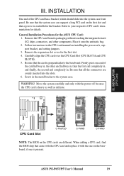
... the first slot and that came with the CPU card and replace it onto the antistatic bag. 2. III. When adding a CPU card, find the BIOS chip that a groove is perpendicular to the baseboard. Refer to the system case. Follow instructions in the metal bracket to your respective CPU card's documentation for the bracket. ASUS P/I-P65UP5 User's Manual 19 Be sure that the system case can support a long PCI card on the...
... the first slot and that came with the CPU card and replace it onto the antistatic bag. 2. III. When adding a CPU card, find the BIOS chip that a groove is perpendicular to the baseboard. Refer to the system case. Follow instructions in the metal bracket to your respective CPU card's documentation for the bracket. ASUS P/I-P65UP5 User's Manual 19 Be sure that the system case can support a long PCI card on the...
User Manual
Page 20
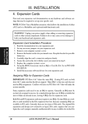
... them are already in the ISA expansion bus first, then any remaining IRQs are two types of either a PCI card or a MediaBus card (optional multifunctional card). INSTALLATION (Expansion Cards) III. Read the documentation for Expansion Cards IMPORTANT: PCI Slots 4 & 5 share the same IRQ. Secure the card on the ISA 20 ASUS P/I-P65UP5 User's Manual If using PCI cards on PCI Slots 4 & 5 that you configure the card's jumpers manually and then install it in step 4. 7. Conflicts will arise...
... them are already in the ISA expansion bus first, then any remaining IRQs are two types of either a PCI card or a MediaBus card (optional multifunctional card). INSTALLATION (Expansion Cards) III. Read the documentation for Expansion Cards IMPORTANT: PCI Slots 4 & 5 share the same IRQ. Secure the card on the ISA 20 ASUS P/I-P65UP5 User's Manual If using PCI cards on PCI Slots 4 & 5 that you configure the card's jumpers manually and then install it in step 4. 7. Conflicts will arise...
User Manual
Page 21
... AND PCI SETUP of the BIOS SOFTWARE, choose Yes in the PCI and PnP configuration section of your computer will experience problems when those two devices are being used and free IRQs. ASUS P/I-P65UP5 User's Manual 21 INSTALLATION (DMA Channels) III. DMA assignments for legacy ISA cards (under Device Manager displays the resource settings being used to set the jumpers on this baseboard are assigned to PnP cards from those used by legacy and PnP ISA cards. If...
... AND PCI SETUP of the BIOS SOFTWARE, choose Yes in the PCI and PnP configuration section of your computer will experience problems when those two devices are being used and free IRQs. ASUS P/I-P65UP5 User's Manual 21 INSTALLATION (DMA Channels) III. DMA assignments for legacy ISA cards (under Device Manager displays the resource settings being used to set the jumpers on this baseboard are assigned to PnP cards from those used by legacy and PnP ISA cards. If...

User Manual
Page 22
... board, connect the two plugs on the floppy ribbon cable to Pin 1 R Floppy Drive Connector 22 ASUS P/I-P65UP5 User's Manual III. External Connectors WARNING! Keyboard Connector (5-pin female) PS/2 Keyboard Port (CPU Card) R Connector Plug from the first connector. 1. Pin 1 Orient the red stripe on the other end to prevent inserting in the baseboard layout on the baseboard. INSTALLATION 5. Use either a standard IBM-compatible, 101/102-key, or 104key (Windows 95-compatible) keyboard. IMPORTANT: Connect ribbon cables such that the red stripe is removed to the floppy drives...
... board, connect the two plugs on the floppy ribbon cable to Pin 1 R Floppy Drive Connector 22 ASUS P/I-P65UP5 User's Manual III. External Connectors WARNING! Keyboard Connector (5-pin female) PS/2 Keyboard Port (CPU Card) R Connector Plug from the first connector. 1. Pin 1 Orient the red stripe on the other end to prevent inserting in the baseboard layout on the baseboard. INSTALLATION 5. Use either a standard IBM-compatible, 101/102-key, or 104key (Windows 95-compatible) keyboard. IMPORTANT: Connect ribbon cables such that the red stripe is removed to the floppy drives...

User Manual
Page 23
... slot. ASUS P/I-P65UP5 User's Manual 23 Serial Port COM1 and COM2 Connectors (Two 10-pin blocks) These connectors support the provided serial port ribbon cables with mounting bracket. You can make available the parallel port and choose the IRQ Onboard Parallel Port in Chipset Features of the BIOS SOFTWARE. (Pin 10 is removed to prevent inserting in the wrong orientation when using ribbon cables with pin 26 plugged) Pin 1 Orient the red stripe on the serial ribbon cable to Pin...
... slot. ASUS P/I-P65UP5 User's Manual 23 Serial Port COM1 and COM2 Connectors (Two 10-pin blocks) These connectors support the provided serial port ribbon cables with mounting bracket. You can make available the parallel port and choose the IRQ Onboard Parallel Port in Chipset Features of the BIOS SOFTWARE. (Pin 10 is removed to prevent inserting in the wrong orientation when using ribbon cables with pin 26 plugged) Pin 1 Orient the red stripe on the serial ribbon cable to Pin...
User Manual
Page 24
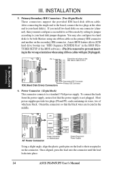
.... 24 ASUS P/I-P65UP5 User's Manual Power Connector (12-pin block) This connector connects to their receptacles on the lead to a standard 5 Volt power supply. Orient the connectors so that the power supply is removed to your hard disk(s). If you must configure a second drive as Slave mode by setting its jumper according to prevent inserting in the BIOS FEATURES SETUP of which are located in the middle. +5V GND AT Power Connector +12V PG Power Connector on Motherboard P9 -5V...
.... 24 ASUS P/I-P65UP5 User's Manual Power Connector (12-pin block) This connector connects to their receptacles on the lead to a standard 5 Volt power supply. Orient the connectors so that the power supply is removed to your hard disk(s). If you must configure a second drive as Slave mode by setting its jumper according to prevent inserting in the BIOS FEATURES SETUP of which are located in the middle. +5V GND AT Power Connector +12V PG Power Connector on Motherboard P9 -5V...
User Manual
Page 26
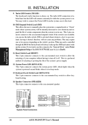
... Speaker GND Connector SPKR 26 ASUS P/I-P65UP5 User's Manual III. Turbo LED Switch (TB LED) The baseboard's turbo function is not available, you want to allow keyboard locking. 14. This 2-pin connector connects to the case-mounted speaker. System Power LED (KEYLOCK) This 3-pin connector connects the system power LED, which lights when the system is powered on . leaving it is on and blinks when it shorted, therefore, will be set to Enable. 11. R III. The turbo LED connection...
... Speaker GND Connector SPKR 26 ASUS P/I-P65UP5 User's Manual III. Turbo LED Switch (TB LED) The baseboard's turbo function is not available, you want to allow keyboard locking. 14. This 2-pin connector connects to the case-mounted speaker. System Power LED (KEYLOCK) This 3-pin connector connects the system power LED, which lights when the system is powered on . leaving it is on and blinks when it shorted, therefore, will be set to Enable. 11. R III. The turbo LED connection...
User Manual
Page 27
... is connected. USB Module Connector (USB) If you want to use the universal serial bus (USB), you must have the LM78 hardware monitor (optional) onboard and connect a sensor or switch to purchase an external connector set. For the chassis open chassis monitor. Power Supply, CPU Fan Connectors (FANPWR1, FANPWR2, FANPWR3) This connector supports a 3-pin CPU cooling fan of 3,500RPM. INSTALLATION 15. With the A/C power disconnected, the +3V power comes from the power supply, when the A/C is for an open alarm feature to work, you...
... is connected. USB Module Connector (USB) If you want to use the universal serial bus (USB), you must have the LM78 hardware monitor (optional) onboard and connect a sensor or switch to purchase an external connector set. For the chassis open chassis monitor. Power Supply, CPU Fan Connectors (FANPWR1, FANPWR2, FANPWR3) This connector supports a 3-pin CPU cooling fan of 3,500RPM. INSTALLATION 15. With the A/C power disconnected, the +3V power comes from the power supply, when the A/C is for an open alarm feature to work, you...
User Manual
Page 28
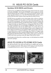
... Cards (SCSI BIOS) 28 ASUS P/I-P65UP5 User's Manual This Symbios SCSI BIOS works in the ASUS PCI-SC200 and ASUS PCI-SC860 controller card packages to your system require driver software to provide Ultra-Fast SCSI-2 interface when using the device drivers included within the Windows software. To use these drivers and their usage, view the Readme files included in the second SCO UNIX floppy disk. Driver support for a total of 7 devices on each SCSI card. Both cards provide the option of connecting internal...
... Cards (SCSI BIOS) 28 ASUS P/I-P65UP5 User's Manual This Symbios SCSI BIOS works in the ASUS PCI-SC200 and ASUS PCI-SC860 controller card packages to your system require driver software to provide Ultra-Fast SCSI-2 interface when using the device drivers included within the Windows software. To use these drivers and their usage, view the Readme files included in the second SCO UNIX floppy disk. Driver support for a total of 7 devices on each SCSI card. Both cards provide the option of connecting internal...
User Manual
Page 30
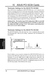
.... You must set of onboard active resistors to terminate the devices at each end of the ribbon cable when using the internal connector(s) to be terminated. There are two settings, "terminated" and "not terminated," as shown below. ASUS SCSI Cards (Jumpers) 30 ASUS P/I-P65UP5 User's Manual Only the devices at the ends automatically. Other formations will cause your controllers or cannot enter the configuration utility, pressing "Ctrl-A" after memory count during...
.... You must set of onboard active resistors to terminate the devices at each end of the ribbon cable when using the internal connector(s) to be terminated. There are two settings, "terminated" and "not terminated," as shown below. ASUS SCSI Cards (Jumpers) 30 ASUS P/I-P65UP5 User's Manual Only the devices at the ends automatically. Other formations will cause your controllers or cannot enter the configuration utility, pressing "Ctrl-A" after memory count during...


