User Manual
Page 3
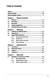
... panel 1-4 1.4 Internal components 1-7 1.5 Qualified Vendors Lists (QVL 1-8 Chapter 2: Starting up 2.1 Installing an operating system 2-2 2.2 Powering up 2-2 2.3 Support DVD information 2-2 2.3.1 Running the support DVD 2-3 2.3.2 Utilities menu 2-4 2.3.3 ASUS Contact information 2-5 2.3.4 Other information 2-6 Chapter 3: Motherboard info 3.1 Introduction 3-2 3.2 Motherboard layout 3-2 3.3 Jumpers 3-3 3.4 Connectors 3-5 Chapter 4: BIOS setup 4.1 Managing and updating your BIOS...
... panel 1-4 1.4 Internal components 1-7 1.5 Qualified Vendors Lists (QVL 1-8 Chapter 2: Starting up 2.1 Installing an operating system 2-2 2.2 Powering up 2-2 2.3 Support DVD information 2-2 2.3.1 Running the support DVD 2-3 2.3.2 Utilities menu 2-4 2.3.3 ASUS Contact information 2-5 2.3.4 Other information 2-6 Chapter 3: Motherboard info 3.1 Introduction 3-2 3.2 Motherboard layout 3-2 3.3 Jumpers 3-3 3.4 Connectors 3-5 Chapter 4: BIOS setup 4.1 Managing and updating your BIOS...
User Manual
Page 7
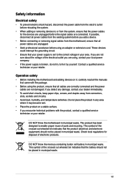
...If you are not sure about the voltage of the electrical outlet you add a device. • Before connecting or removing signal cables from the motherboard, ensure that all power cables from the existing system before you are not damaged. These devices could interrupt the grounding circuit. • Ensure that... your power supply is broken, do not try to fix it by yourself. DO NOT throw the motherboard in municipal waste. This product has been designed to enable proper reuse of the crossed out wheeled bin indicates that the battery should not ...
...If you are not sure about the voltage of the electrical outlet you add a device. • Before connecting or removing signal cables from the motherboard, ensure that all power cables from the existing system before you are not damaged. These devices could interrupt the grounding circuit. • Ensure that... your power supply is broken, do not try to fix it by yourself. DO NOT throw the motherboard in municipal waste. This product has been designed to enable proper reuse of the crossed out wheeled bin indicates that the battery should not ...
User Manual
Page 8
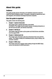
...support DVD. 3. How this guide Audience This guide provides general information and installation instructions about the motherboard that comes with hardware knowledge of the ASUS P6-P5G41E. Chapter 1: System introduction This chapter gives a general description of personal computers. Chapter 4: BIOS ... features, including introduction on the front and rear panel, and internal components. 2. Chapter 3: Motherboard info This chapter gives information about the ASUS P6-P5G41E barebone system. About this guide is intended for experienced users and integrators with the system. This...
...support DVD. 3. How this guide Audience This guide provides general information and installation instructions about the motherboard that comes with hardware knowledge of the ASUS P6-P5G41E. Chapter 1: System introduction This chapter gives a general description of personal computers. Chapter 4: BIOS ... features, including introduction on the front and rear panel, and internal components. 2. Chapter 3: Motherboard info This chapter gives information about the ASUS P6-P5G41E barebone system. About this guide is intended for experienced users and integrators with the system. This...
User Manual
Page 12
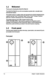
The system comes in a stylish casing and powered by the ASUS motherboard that supports the Intel® Core™2 Extreme / Core™2 Duo / Core™2 Quad / Pentium® dual-core / Celeron® processors in the world of ... graphics via integrated graphics controller or PCI Express x16 slot, Serial ATA, USB 2.0, and 8-channel audio feature the system and take you for choosing the ASUS P6-P5G41E! 1.1 Welcome! The system supports up to 8 GB of power computing. 1.2 Front panel The front panel includes the optical drive bays, power button, and several I/O ports...
The system comes in a stylish casing and powered by the ASUS motherboard that supports the Intel® Core™2 Extreme / Core™2 Duo / Core™2 Quad / Pentium® dual-core / Celeron® processors in the world of ... graphics via integrated graphics controller or PCI Express x16 slot, Serial ATA, USB 2.0, and 8-channel audio feature the system and take you for choosing the ASUS P6-P5G41E! 1.1 Welcome! The system supports up to 8 GB of power computing. 1.2 Front panel The front panel includes the optical drive bays, power button, and several I/O ports...
User Manual
Page 17
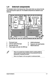
... components are labeled for your reference. 2 1 4 3 5 5 6 7 1. Power supply unit (under the HDD bay) • Refer to the Chapter 4 in this user guide for motherboard details. ASUS P6-P5G41E 1-7 Metal bracket lock 4. ASUS motherboard 2. 5.25-inch optical drive bays 6. Hard disk drive bay 7. 1.4 Internal components The illustration below is the internal view of the system when you...
... components are labeled for your reference. 2 1 4 3 5 5 6 7 1. Power supply unit (under the HDD bay) • Refer to the Chapter 4 in this user guide for motherboard details. ASUS P6-P5G41E 1-7 Metal bracket lock 4. ASUS motherboard 2. 5.25-inch optical drive bays 6. Hard disk drive bay 7. 1.4 Internal components The illustration below is the internal view of the system when you...
User Manual
Page 23
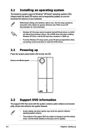
...maximize the features of the support DVD are subject to your hardware. Refer to change at any time without the necessary drivers. Motherboard settings and hardware options vary. Press to turn ON the system 2.3 Support DVD information The support DVD that came with the system...for updates. 2-2 Chapter 2: Starting up Press the system power button ( ) to install the SATA drivers. 2.2 Powering up Visit the ASUS website at www.asus.com for different operating system versions. • The contents of your OS documentation for general reference only. Use a RAID driver disk ...
...maximize the features of the support DVD are subject to your hardware. Refer to change at any time without the necessary drivers. Motherboard settings and hardware options vary. Press to turn ON the system 2.3 Support DVD information The support DVD that came with the system...for updates. 2-2 Chapter 2: Starting up Press the system power button ( ) to install the SATA drivers. 2.2 Powering up Visit the ASUS website at www.asus.com for different operating system versions. • The contents of your OS documentation for general reference only. Use a RAID driver disk ...

User Manual
Page 24
.../motherboard information Click an item to install If Autorun is enabled in your computer, browse the contents of the support DVD to locate the file ASSETUP.EXE from the latest threats. Double-click the ASSETUP.EXE to protect your optical drive. Realtek Audio Driver Installs the Realtek audio driver and application. ASUS P6-P5G41E...
.../motherboard information Click an item to install If Autorun is enabled in your computer, browse the contents of the support DVD to locate the file ASSETUP.EXE from the latest threats. Double-click the ASSETUP.EXE to protect your optical drive. Realtek Audio Driver Installs the Realtek audio driver and application. ASUS P6-P5G41E...
User Manual
Page 25
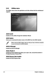
..., make sure that allows you to open, view, and print documents in Portable Document Format (PDF). ASUS AI Manager Installs the ASUS AI Manager. ASUS Express Gate Installer Installs the ASUS Express Gate. 2-4 Chapter 2: Starting up ASUS Update Allows you to download the latest version of the utilities through the Installation Wizard. 2.3.2 Utilities menu The...
..., make sure that allows you to open, view, and print documents in Portable Document Format (PDF). ASUS AI Manager Installs the ASUS AI Manager. ASUS Express Gate Installer Installs the ASUS Express Gate. 2-4 Chapter 2: Starting up ASUS Update Allows you to download the latest version of the utilities through the Installation Wizard. 2.3.2 Utilities menu The...
User Manual
Page 27
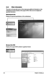
Click an icon to display the specified information. Browse this DVD Displays the support DVD contents in graphical format. 2-6 Chapter 2: Starting up Motherboard Info Displays the general specifications of the support DVD. 2.3.4 Other information The icons on the top right corner of the screen give additional information on the motherboard and the contents of the motherboard.
Click an icon to display the specified information. Browse this DVD Displays the support DVD contents in graphical format. 2-6 Chapter 2: Starting up Motherboard Info Displays the general specifications of the support DVD. 2.3.4 Other information The icons on the top right corner of the screen give additional information on the motherboard and the contents of the motherboard.
User Manual
Page 30
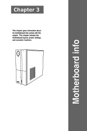
This chapter includes the motherboard layout, jumper settings, and connector locations. Motherboard info Chapter 3 This chapter gives information about he motherboard that comes with the system.
This chapter includes the motherboard layout, jumper settings, and connector locations. Motherboard info Chapter 3 This chapter gives information about he motherboard that comes with the system.
User Manual
Page 31
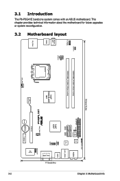
3.1 Introduction The P6-P5G41E barebone system comes with an ASUS motherboard. This chapter provides technical information about the motherboard for future upgrades or system reconfiguration. 3.2 Motherboard layout 33.5cm(13.2in) USBPW5-6 F_PANEL DDR3 DIMM_B1 (64bit, 240-pin module) DDR3 DIMM_A1 (64bit, 240-pin module) FRONT_ AUD USB56 ATX12V LGA775 Intel&#... SATA2 SATA1 RTL 8111C LAN1_USB34 Intel® ICH7 USBPW1-4 COM1 USB12 VGA_HDMI CHA_FAN1 PCIEX16 BUZZER Lithium Cell CMOS Power Super I/O DEBUGPORT 17.5cm(6.9in) 3-2 Chapter 3: Motherboard info
3.1 Introduction The P6-P5G41E barebone system comes with an ASUS motherboard. This chapter provides technical information about the motherboard for future upgrades or system reconfiguration. 3.2 Motherboard layout 33.5cm(13.2in) USBPW5-6 F_PANEL DDR3 DIMM_B1 (64bit, 240-pin module) DDR3 DIMM_A1 (64bit, 240-pin module) FRONT_ AUD USB56 ATX12V LGA775 Intel&#... SATA2 SATA1 RTL 8111C LAN1_USB34 Intel® ICH7 USBPW1-4 COM1 USB12 VGA_HDMI CHA_FAN1 PCIEX16 BUZZER Lithium Cell CMOS Power Super I/O DEBUGPORT 17.5cm(6.9in) 3-2 Chapter 3: Motherboard info
User Manual
Page 33
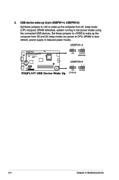
2. Set these jumpers to +5V to CPU, DRAM in slow refresh, power supply in low power mode) using the connected USB devices. USBPW1-4 12 23 P5QPL10T +5V +5VSB (Default) USBPW5-6 12 23 +5V +5VSB P5QPL10T USB Device Wake Up (Default) 3-4 Chapter 3: Motherboard info USB device wake-up (3-pin USBPW1-4, USBPW5-6) Set these jumpers to +5VSB to wake up the computer from S3 and S4 sleep modes (no power to wake up the compurer from S1 sleep mode (CPU stopped, DRAM refreshed, system running in reduced power mode).
2. Set these jumpers to +5V to CPU, DRAM in slow refresh, power supply in low power mode) using the connected USB devices. USBPW1-4 12 23 P5QPL10T +5V +5VSB (Default) USBPW5-6 12 23 +5V +5VSB P5QPL10T USB Device Wake Up (Default) 3-4 Chapter 3: Motherboard info USB device wake-up (3-pin USBPW1-4, USBPW5-6) Set these jumpers to +5VSB to wake up the computer from S3 and S4 sleep modes (no power to wake up the compurer from S1 sleep mode (CPU stopped, DRAM refreshed, system running in reduced power mode).
User Manual
Page 34
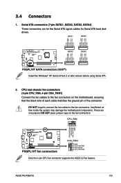
...Serial ATA signal cables for Serial ATA hard disk drives. DO NOT place jumper caps on the motherboard, ensuring that the black wire of each cable matches the ground pin of the connector. ASUS P6-P5G41E 3-5 CPU_FAN CPU FAN PWM CPU FAN IN CPU FAN PWR GND P5QPL10T P5QPL10T fan connectors CHA_FAN1... GND CPU FAN PWR CPU FAN IN CPU FAN PWM Only the 4-pin CPU fan connector supports the ASUS Q-Fan feature. 3.4 Connectors 1. CPU and ...
...Serial ATA signal cables for Serial ATA hard disk drives. DO NOT place jumper caps on the motherboard, ensuring that the black wire of each cable matches the ground pin of the connector. ASUS P6-P5G41E 3-5 CPU_FAN CPU FAN PWM CPU FAN IN CPU FAN PWR GND P5QPL10T P5QPL10T fan connectors CHA_FAN1... GND CPU FAN PWR CPU FAN IN CPU FAN PWM Only the 4-pin CPU fan connector supports the ASUS Q-Fan feature. 3.4 Connectors 1. CPU and ...
User Manual
Page 35
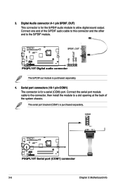
.... 4. P5QPL10T SPDIF_OUT +5V SPDIFOUT GND P5QPL10T Digital audio connector The S/PDIF out module is purchased separately. COM1 PIN 1 P5QPL10T P5QPL10T Serial port (COM1) connector 3-6 Chapter 3: Motherboard info
.... 4. P5QPL10T SPDIF_OUT +5V SPDIFOUT GND P5QPL10T Digital audio connector The S/PDIF out module is purchased separately. COM1 PIN 1 P5QPL10T P5QPL10T Serial port (COM1) connector 3-6 Chapter 3: Motherboard info
User Manual
Page 36
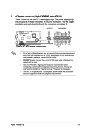
The power supply plugs are for ATX power supply plugs. ASUS P6-P5G41E 3-7 5. otherwise, the system will not boot. • Use of 200W~250W. • DO NOT forget to fit these connectors in only one orientation. ATX12V EATXPWR... when configuring a system with a higher power output is inadequate. • The ATX 12 V Specification 2.0-compliant (200W~250W) PSU has been tested to support the motherboard power requirements. ATX power connectors (24-pin EATXPWR, 4-pin ATX12V) These connectors are designed to connect the 4-pin ATX12V power plug; Find the proper orientation...
The power supply plugs are for ATX power supply plugs. ASUS P6-P5G41E 3-7 5. otherwise, the system will not boot. • Use of 200W~250W. • DO NOT forget to fit these connectors in only one orientation. ATX12V EATXPWR... when configuring a system with a higher power output is inadequate. • The ATX 12 V Specification 2.0-compliant (200W~250W) PSU has been tested to support the motherboard power requirements. ATX power connectors (24-pin EATXPWR, 4-pin ATX12V) These connectors are designed to connect the 4-pin ATX12V power plug; Find the proper orientation...
User Manual
Page 37
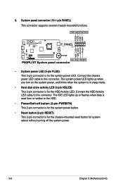
... disk drive activity LED (2-pin HDLED) This 2-pin connector is read from or written to the HDD. • Power/Soft-off the system power. 3-8 Chapter 3: Motherboard info Connect the chassis power LED cable to this connector. The system power LED lights up or flashes when data is for the HDD Activity...
... disk drive activity LED (2-pin HDLED) This 2-pin connector is read from or written to the HDD. • Power/Soft-off the system power. 3-8 Chapter 3: Motherboard info Connect the chassis power LED cable to this connector. The system power LED lights up or flashes when data is for the HDD Activity...
User Manual
Page 39
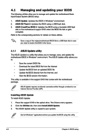
...the BIOS in Windows® environment. ASUS Update: Updates the BIOS in the optical drive. Quit all Windows® applications before you to manage, save, and update the motherboard BIOS in the future. 4.1.1 ASUS Update utility The ASUS Update is copied to the corresponding ...sections for details on these utilities. The ASUS Update utility allows you to manage and update the motherboard Basic Input/Output System (BIOS) setup. 1. The ASUS Update utility is ...
...the BIOS in Windows® environment. ASUS Update: Updates the BIOS in the optical drive. Quit all Windows® applications before you to manage, save, and update the motherboard BIOS in the future. 4.1.1 ASUS Update utility The ASUS Update is copied to the corresponding ...sections for details on these utilities. The ASUS Update utility allows you to manage and update the motherboard Basic Input/Output System (BIOS) setup. 1. The ASUS Update utility is ...
User Manual
Page 43
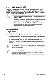
...floppy disk drive, if supported. 3. Recovering the BIOS To recover the BIOS: 1. DO NOT shut down or reset the system while updating the BIOS! For motherboards without the floppy connector, prepare a USB flash disk before using this utility. Turn on again. Turn off the system after the utility completes the updating... can cause system boot failure! The utility automatically checks the devices for details. 4-6 Chapter 4: BIOS setup Doing so can restore a corrupted BIOS file using the motherboard support DVD or a removable device that ASUS CrashFree BIOS support vary with...
...floppy disk drive, if supported. 3. Recovering the BIOS To recover the BIOS: 1. DO NOT shut down or reset the system while updating the BIOS! For motherboards without the floppy connector, prepare a USB flash disk before using this utility. Turn on again. Turn off the system after the utility completes the updating... can cause system boot failure! The utility automatically checks the devices for details. 4-6 Chapter 4: BIOS setup Doing so can restore a corrupted BIOS file using the motherboard support DVD or a removable device that ASUS CrashFree BIOS support vary with...
User Manual
Page 44
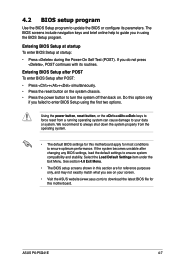
... or the ++ keys to force reset from the operating system. • The default BIOS settings for this motherboard apply for most conditions to ensure optimum performance. ASUS P6-P5G41E 4-7 We recommend to always shut down the system properly from a running operating system can cause damage to your... screen. • Visit the ASUS website (www.asus.com) to enter BIOS Setup using the BIOS Setup ...
... or the ++ keys to force reset from the operating system. • The default BIOS settings for this motherboard apply for most conditions to ensure optimum performance. ASUS P6-P5G41E 4-7 We recommend to always shut down the system properly from a running operating system can cause damage to your... screen. • Visit the ASUS website (www.asus.com) to enter BIOS Setup using the BIOS Setup ...

User Manual
Page 60
... speed in rotations per minute (RPM). If the fan is not connected to the chassis, the specific field shows N/A. ASUS P6-P5G41E 4-23 The onboard hardware monitor automatically detects and displays the CPU / motherboard temperatures. Select Ignored if you do not wish to display the detected speed. Select Ignored if you do not wish...
... speed in rotations per minute (RPM). If the fan is not connected to the chassis, the specific field shows N/A. ASUS P6-P5G41E 4-23 The onboard hardware monitor automatically detects and displays the CPU / motherboard temperatures. Select Ignored if you do not wish to display the detected speed. Select Ignored if you do not wish...


