
Motherboard Installation Guide
Page 7
... is set to the correct voltage in your dealer immediately. • To avoid short circuits, keep paper clips, screws, and staples away from connectors, slots, sockets and circuitry. • Avoid dust, humidity, and temperature extremes. Check local regulations for the devices are unplugged before using the product, make sure all power...
... is set to the correct voltage in your dealer immediately. • To avoid short circuits, keep paper clips, screws, and staples away from connectors, slots, sockets and circuitry. • Avoid dust, humidity, and temperature extremes. Check local regulations for the devices are unplugged before using the product, make sure all power...
Motherboard Installation Guide
Page 14
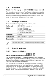
The motherboard supports the Intel® Pentium® 4 processor with a 775-pin surface mount Land Grid Array (LGA) socket designed for details. 1-2 Chapter 1: Hardware information The motherboard also supports the Intel® Hyper-Threading Technology, the Intel® Extended Memory..., check the items in the long line of the above items is damaged or missing, contact your motherboard package for the following items. Motherboard ASUS P5VDC-X motherboard Cables 1 x Serial ATA cable 1 x Serial ATA power cable 1 x Ultra DMA 133/100/66 cable 1 x Floppy disk drive cable Accessories...
The motherboard supports the Intel® Pentium® 4 processor with a 775-pin surface mount Land Grid Array (LGA) socket designed for details. 1-2 Chapter 1: Hardware information The motherboard also supports the Intel® Hyper-Threading Technology, the Intel® Extended Memory..., check the items in the long line of the above items is damaged or missing, contact your motherboard package for the following items. Motherboard ASUS P5VDC-X motherboard Cables 1 x Serial ATA cable 1 x Serial ATA power cable 1 x Ultra DMA 133/100/66 cable 1 x Floppy disk drive cable Accessories...
Motherboard Installation Guide
Page 17
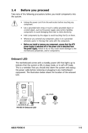
... or in soft-off or the power cord is switched off mode. Top:Line In Center:Line Out Below:Mic In P5VDC-X R P5VDC-X Onboard LED SB_PWR ON Standby Power OFF Powered Off ASUS P5VDC-X 1-5 1.4 Before you proceed Take note of the onboard LED. Failure to do so may cause severe damage to the..., or in the bag that came with a standby power LED that lights up to indicate that the ATX power supply is detached from the wall socket before touching any component. • Use a grounded wrist strap or touch a safely grounded object or a metal object, such as the power supply case, ...
... or in soft-off or the power cord is switched off mode. Top:Line In Center:Line Out Below:Mic In P5VDC-X R P5VDC-X Onboard LED SB_PWR ON Standby Power OFF Powered Off ASUS P5VDC-X 1-5 1.4 Before you proceed Take note of the onboard LED. Failure to do so may cause severe damage to the..., or in the bag that came with a standby power LED that lights up to indicate that the ATX power supply is detached from the wall socket before touching any component. • Use a grounded wrist strap or touch a safely grounded object or a metal object, such as the power supply case, ...

Motherboard Installation Guide
Page 20
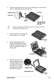
Top:Line In Center:Line Out Below:Mic In P5VDC-X R P5VDC-X CPU Socket 775 Before installing the CPU, make sure that the socket box is facing towards you see any damage to the socket contacts resulting from incorrect CPU installation/removal, or misplacement/loss/incorrect removal of the PnP cap. 1.6.1 Installing the...documentation, follow the latter. • Upon purchase of the motherboard, make sure that the PnP cap is on the socket and the socket contacts are not bent. ASUS will shoulder the cost of repair only if the damage is missing, or if you and the load lever is ...
Top:Line In Center:Line Out Below:Mic In P5VDC-X R P5VDC-X CPU Socket 775 Before installing the CPU, make sure that the socket box is facing towards you see any damage to the socket contacts resulting from incorrect CPU installation/removal, or misplacement/loss/incorrect removal of the PnP cap. 1.6.1 Installing the...documentation, follow the latter. • Upon purchase of the motherboard, make sure that the PnP cap is on the socket and the socket contacts are not bent. ASUS will shoulder the cost of repair only if the damage is missing, or if you and the load lever is ...
Motherboard Installation Guide
Page 21
... the bottom-left (B) until it to the left corner of the arrow to the socket pins, do not remove the PnP cap unless you . Lift the load plate with your thumb and forefinger to remove (B). Alignment key Gold triangle mark ASUS P5VDC-X 1-9 2. The socket alignment keys should face you are installing a CPU. 3.
... the bottom-left (B) until it to the left corner of the arrow to the socket pins, do not remove the PnP cap unless you . Lift the load plate with your thumb and forefinger to remove (B). Alignment key Gold triangle mark ASUS P5VDC-X 1-9 2. The socket alignment keys should face you are installing a CPU. 3.
Motherboard Installation Guide
Page 22
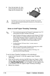
...(see Chapter 2: BIOS setup). B The CPU fits in only one correct orientation. Under Linux, use the Hyper-Threading Technology on the socket and damaging the CPU. Reboot the computer. 1-10 Chapter 1: Hardware information 6. DO NOT force the CPU into the retention tab. To use ...recommended. • Make sure to compile the code. Close the load plate (A), then push the load lever (B) until it A snaps into the socket to Enabled. Install an Intel® Pentium® 4 CPU that supports Hyper-Threading Technology. 3. Under the Advanced BIOS Features Menu, make sure ...
...(see Chapter 2: BIOS setup). B The CPU fits in only one correct orientation. Under Linux, use the Hyper-Threading Technology on the socket and damaging the CPU. Reboot the computer. 1-10 Chapter 1: Hardware information 6. DO NOT force the CPU into the retention tab. To use ...recommended. • Make sure to compile the code. Close the load plate (A), then push the load lever (B) until it A snaps into the socket to Enabled. Install an Intel® Pentium® 4 CPU that supports Hyper-Threading Technology. 3. Under the Advanced BIOS Features Menu, make sure ...
Motherboard Installation Guide
Page 27
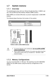
ASUS P5VDC-X 1-15 The following figure illustrates the location of the sockets: Color Blue Yellow Sockets DDR_1 and DDR_2 DDR2_1 and DDR2_2 Top:Line In Center:Line Out Below:Mic In P5VDC-X R DDR2_B1 DDR2_A1 DDR_B1 DDR_A1 P5VDC-X DDR & DDR2 DIMM Sockets • To prevent damage to the motherboard, do not use DDR and DDR2 memory simultaneously. •...
ASUS P5VDC-X 1-15 The following figure illustrates the location of the sockets: Color Blue Yellow Sockets DDR_1 and DDR_2 DDR2_1 and DDR2_2 Top:Line In Center:Line Out Below:Mic In P5VDC-X R DDR2_B1 DDR2_A1 DDR_B1 DDR_A1 P5VDC-X DDR & DDR2 DIMM Sockets • To prevent damage to the motherboard, do not use DDR and DDR2 memory simultaneously. •...

Motherboard Installation Guide
Page 30
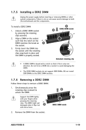
...do so may cause severe damage to avoid damaging the DIMM. 3. DO NOT force a DIMM into the socket until the retaining clips snap back in only one direction. Align a DIMM on the socket such that it fits in place and the DIMM is keyed with extra force. 2. Firmly insert...components. 1. The DIMM might get damaged when it flips out with a notch so that the notch on the DIMM matches the break on the socket. 1 2 DDR DIMM notch 1 Unlocked retaining clip A DDR DIMM is properly seated. Simultaneously press the retaining clips outward to unplug the power supply before...
...do so may cause severe damage to avoid damaging the DIMM. 3. DO NOT force a DIMM into the socket until the retaining clips snap back in only one direction. Align a DIMM on the socket such that it fits in place and the DIMM is keyed with extra force. 2. Firmly insert...components. 1. The DIMM might get damaged when it flips out with a notch so that the notch on the DIMM matches the break on the socket. 1 2 DDR DIMM notch 1 Unlocked retaining clip A DDR DIMM is properly seated. Simultaneously press the retaining clips outward to unplug the power supply before...
Motherboard Installation Guide
Page 31
... pressing the retaining clips. Remove the DIMM from the socket. Align a DIMM on 1 the socket. 3. Support the DIMM lightly with extra force. 1 DDR2 DIMM notch 2. The DIMM might get damaged when it fits in only one direction. ASUS P5VDC-X 1-19 To install a DDR2 DIMM: 1. Firmly ...insert the DIMM into a socket to avoid damaging the DIMM. • The DDR2 DIMM sockets do so can cause severe damage to remove a DDR2 DIMM. 1. Simultaneously ...
... pressing the retaining clips. Remove the DIMM from the socket. Align a DIMM on 1 the socket. 3. Support the DIMM lightly with extra force. 1 DDR2 DIMM notch 2. The DIMM might get damaged when it fits in only one direction. ASUS P5VDC-X 1-19 To install a DDR2 DIMM: 1. Firmly ...insert the DIMM into a socket to avoid damaging the DIMM. • The DDR2 DIMM sockets do so can cause severe damage to remove a DDR2 DIMM. 1. Simultaneously ...

Motherboard DIY Troubleshooting Guide
Page 20
® • ® ® • • • Top:Line In Center:Line Out Below:Mic In P5VDC-X R P5VDC-X CPU Socket 775 1-8
® • ® ® • • • Top:Line In Center:Line Out Below:Mic In P5VDC-X R P5VDC-X CPU Socket 775 1-8

Motherboard DIY Troubleshooting Guide
Page 27
Top:Line In Center:Line Out Below:Mic In P5VDC-X R P5VDC-X DDR & DDR2 DIMM Sockets DDR2_B1 DDR2_A1 DDR_B1 DDR_A1 1-15
Top:Line In Center:Line Out Below:Mic In P5VDC-X R P5VDC-X DDR & DDR2 DIMM Sockets DDR2_B1 DDR2_A1 DDR_B1 DDR_A1 1-15


