
Motherboard Installation Guide
Page 66
... Save and Exit ESC Exit 4-12 Change Field Tab Select Field F1 General Help F10 Save and Exit ESC Exit Advanced Chipset settings WARNING: Setting wrong values in ] [English] :[ST320413A] :[ASUS CD-S340] :[Not Detected] :[Not Detected] :[Not Detected] :[Not Detected] Use [ENTER], [TAB] or [SHIFT-TAB] to select a field. Use [+] or...
... Save and Exit ESC Exit 4-12 Change Field Tab Select Field F1 General Help F10 Save and Exit ESC Exit Advanced Chipset settings WARNING: Setting wrong values in ] [English] :[ST320413A] :[ASUS CD-S340] :[Not Detected] :[Not Detected] :[Not Detected] :[Not Detected] Use [ENTER], [TAB] or [SHIFT-TAB] to select a field. Use [+] or...
Motherboard Installation Guide
Page 70
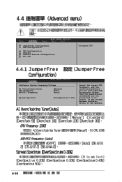
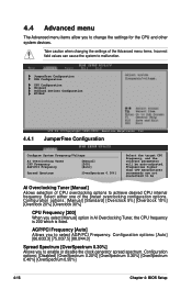
JumperFree Configuration USB Configuration CPU Configuration Chipset Onboard Devices Configuration PCI PnP Configure CPU. Configure System Frequency/Voltage AI Overclocking Tuner CPU Frequency AGP/PCI Frequency [Manual] [200] [Auto] Spread Spectrum [OverSpectrum 0.30%] Select the target CPU frequency, and the relevant parameters will be stable. Frequencies higher than CPU manufacturer recommends are not guaranteed to the default. 4-16 If the system becomes unstable, return to be auto-adjusted.
JumperFree Configuration USB Configuration CPU Configuration Chipset Onboard Devices Configuration PCI PnP Configure CPU. Configure System Frequency/Voltage AI Overclocking Tuner CPU Frequency AGP/PCI Frequency [Manual] [200] [Auto] Spread Spectrum [OverSpectrum 0.30%] Select the target CPU frequency, and the relevant parameters will be stable. Frequencies higher than CPU manufacturer recommends are not guaranteed to the default. 4-16 If the system becomes unstable, return to be auto-adjusted.

Motherboard Installation Guide
Page 73
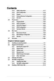
Change Option F1 General Help F10 Save and Exit ESC Exit 4-19 Advanced Chipset Settings WARNING: Setting wrong values in below sections may cause system to malfunction. Options for DRAM Select Screen Select Item +- Change Option F1 General Help F10 Save and Exit ESC Exit DRAM Clock/Timing Configuration AGP & P2P Bridge Configuration V-Link & PCI Bus Configuration Options for VIA PT880U NorthBridge VIA PT880Ultra Configuration SouthBridge VIA VT8237R Configuration Select Screen Select Item +-
Change Option F1 General Help F10 Save and Exit ESC Exit 4-19 Advanced Chipset Settings WARNING: Setting wrong values in below sections may cause system to malfunction. Options for DRAM Select Screen Select Item +- Change Option F1 General Help F10 Save and Exit ESC Exit DRAM Clock/Timing Configuration AGP & P2P Bridge Configuration V-Link & PCI Bus Configuration Options for VIA PT880U NorthBridge VIA PT880Ultra Configuration SouthBridge VIA VT8237R Configuration Select Screen Select Item +-
P5VD1-X User's Manual for English Edition
Page 5
Contents 4.4.2 USB Configuration 4-17 4.4.3 CPU Configuration 4-18 4.4.4 Chipset 4-19 4.4.5 Onboard Devices Configuration 4-23 4.4.6 PCI PnP 4-24 4.5 Power menu 4-25 ...Software support 5.1 Installing an operating system 5-1 5.2 Support CD information 5-1 5.2.1 Running the support CD 5-1 5.2.2 Drivers menu 5-2 5.2.3 Utilities menu 5-3 5.2.4 Manuals menu 5-4 5.2.5 ASUS Contact information 5-5 5.2.6 Other information 5-5 5.3 Software information 5-7 5.4 VIA RAID configurations 5-9 5.4.1 Installing hard disks 5-9 5.4.2 VIA RAID configurations 5-10 5.5...
Contents 4.4.2 USB Configuration 4-17 4.4.3 CPU Configuration 4-18 4.4.4 Chipset 4-19 4.4.5 Onboard Devices Configuration 4-23 4.4.6 PCI PnP 4-24 4.5 Power menu 4-25 ...Software support 5.1 Installing an operating system 5-1 5.2 Support CD information 5-1 5.2.1 Running the support CD 5-1 5.2.2 Drivers menu 5-2 5.2.3 Utilities menu 5-3 5.2.4 Manuals menu 5-4 5.2.5 ASUS Contact information 5-5 5.2.6 Other information 5-5 5.3 Software information 5-7 5.4 VIA RAID configurations 5-9 5.4.1 Installing hard disks 5-9 5.4.2 VIA RAID configurations 5-10 5.5...
P5VD1-X User's Manual for English Edition
Page 10
P5VD1-X Specifications Summary CPU Chipset Front Side Bus Memory Expansion slots Storage/RAID Audio LAN Overclocking Features USB Other ASUS Special Features BIOS features LGA775 socket for Intel® Pentium® D/Pentium® 4/Celeron CPU Supports Intel® Hyper-Threading ...133/100 *2 x Serial ATA with RAID 0, 1, JBOD ADI AD1888 SoundMAX 6-channel CODEC S/PDIF out on back I/O port Intel 82540EM Gigabit LAN Controller ASUS C.P.R. (CPU Parameter Recall) CPU voltage adjustable SFS (Stepless Frequency Selection) from 133 MHz up to 400 MHz at 1 MHz increment Adjustable FSB/DDR ratio...
P5VD1-X Specifications Summary CPU Chipset Front Side Bus Memory Expansion slots Storage/RAID Audio LAN Overclocking Features USB Other ASUS Special Features BIOS features LGA775 socket for Intel® Pentium® D/Pentium® 4/Celeron CPU Supports Intel® Hyper-Threading ...133/100 *2 x Serial ATA with RAID 0, 1, JBOD ADI AD1888 SoundMAX 6-channel CODEC S/PDIF out on back I/O port Intel 82540EM Gigabit LAN Controller ASUS C.P.R. (CPU Parameter Recall) CPU voltage adjustable SFS (Stepless Frequency Selection) from 133 MHz up to 400 MHz at 1 MHz increment Adjustable FSB/DDR ratio...
P5VD1-X User's Manual for English Edition
Page 29
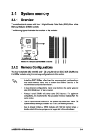
...pairs for each channel. • Always install DIMMs with the same CAS latency. ASUS P5VD1-X Motherboard 2-9 For optimum compatibility, it is recommended that you obtain memory modules from the same vendor. • Due to chipset resource allocation, the system may detect less than 4 GB system memory whne you installed... four 1 GB DDR memory modules. • Due to chipset limitation, DIMM modules with four 184-pin Double Data Rate (DDR) Dual Inline Memory Modules (DIMM) sockets. 2.4 System memory 2.4.1 Overview...
...pairs for each channel. • Always install DIMMs with the same CAS latency. ASUS P5VD1-X Motherboard 2-9 For optimum compatibility, it is recommended that you obtain memory modules from the same vendor. • Due to chipset resource allocation, the system may detect less than 4 GB system memory whne you installed... four 1 GB DDR memory modules. • Due to chipset limitation, DIMM modules with four 184-pin Double Data Rate (DDR) Dual Inline Memory Modules (DIMM) sockets. 2.4 System memory 2.4.1 Overview...
P5VD1-X User's Manual for English Edition
Page 43
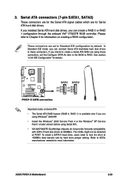
... ATA connectors (7-pin SATA1, SATA2) These connectors are for the Serial ATA signal cables which are set using Serial ATA. • VIA 8237/8237R Southbridge chipsets do not provide forwards compatibility with SATA-II hard disk drives at 300MB/s. If you can connect Serial ATA boot/data hard disk drives to... the Windows® XP Service Pack1 or later version before using these connectors. See section "4.3.6 IDE Configuration" for Serial ATA hard disk drives. ASUS P5VD1-X Motherboard 2-23
... ATA connectors (7-pin SATA1, SATA2) These connectors are for the Serial ATA signal cables which are set using Serial ATA. • VIA 8237/8237R Southbridge chipsets do not provide forwards compatibility with SATA-II hard disk drives at 300MB/s. If you can connect Serial ATA boot/data hard disk drives to... the Windows® XP Service Pack1 or later version before using these connectors. See section "4.3.6 IDE Configuration" for Serial ATA hard disk drives. ASUS P5VD1-X Motherboard 2-23
P5VD1-X User's Manual for English Edition
Page 66
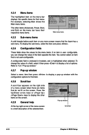
...Slave Secondary IDE Master Secondary IDE Slave System Information [11:51:19] [Sun 01/16/2005] [1.44M, 3.5 in] [Disabled] :[ST340014A] :[Not Detected] :[ASUS DVD-E616P2] :[Not Detected] Use [ENTER], [TAB] or [SHIFT-TAB] to malfunction. You cannot select an item that is a brief description of a menu... selected. Press the Up/Down arrow keys or / keys to display a pop-up window Scroll bar 4-12 Chapter 4: BIOS Setup Advanced Chipset settings WARNING: Setting wrong values in brackets, and is user- Configure DRAM Timing by SPD Memory Acceleration Mode DRAM Idle Timer DRAm Refresh Rate...
...Slave Secondary IDE Master Secondary IDE Slave System Information [11:51:19] [Sun 01/16/2005] [1.44M, 3.5 in] [Disabled] :[ST340014A] :[Not Detected] :[ASUS DVD-E616P2] :[Not Detected] Use [ENTER], [TAB] or [SHIFT-TAB] to malfunction. You cannot select an item that is a brief description of a menu... selected. Press the Up/Down arrow keys or / keys to display a pop-up window Scroll bar 4-12 Chapter 4: BIOS Setup Advanced Chipset settings WARNING: Setting wrong values in brackets, and is user- Configure DRAM Timing by SPD Memory Acceleration Mode DRAM Idle Timer DRAm Refresh Rate...
P5VD1-X User's Manual for English Edition
Page 70
... menu items allow you to enable or disable the clock generator spread spectrum. JumperFree Configuration USB Configuration CPU Configuration Chipset Onboard Devices Configuration PCIPnP 4.4.1 v02.58 (C)Copyright 1985-2004, American Megatrends, Inc. Frequencies higher than CPU manufacturer recommends are not guaranteed to malfunction...
... menu items allow you to enable or disable the clock generator spread spectrum. JumperFree Configuration USB Configuration CPU Configuration Chipset Onboard Devices Configuration PCIPnP 4.4.1 v02.58 (C)Copyright 1985-2004, American Megatrends, Inc. Frequencies higher than CPU manufacturer recommends are not guaranteed to malfunction...

P5VD1-X User's Manual for English Edition
Page 73
... & PCI Bus Configuration Options for VIA PT880U Enter F1 F10 ESC Select Screen Select Item Go to display the sub-menu. ASUS P5VD1-X Motherboard 4-19 Advanced Chipset Settings WARNING: Setting wrong values in below sections may cause system to Sub Screen General Help Save and Exit Exit v02.58 (C)Copyright 1985...
... & PCI Bus Configuration Options for VIA PT880U Enter F1 F10 ESC Select Screen Select Item Go to display the sub-menu. ASUS P5VD1-X Motherboard 4-19 Advanced Chipset Settings WARNING: Setting wrong values in below sections may cause system to Sub Screen General Help Save and Exit Exit v02.58 (C)Copyright 1985...
P5VD1-X User's Manual for English Edition
Page 77
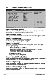
... to Select Serial Port2 Base Addresses. ←→ Select Screen ↑↓ Select Item +- 4.4.5 Onboard Devices Configuration Configure Win627EHF Super IO Chipset Serial Port2 Address Serial Port2 Mode Parallel Port Address Parallel Port Mode ECP Mode DMA Channel Parallel Port IRQ Onboard Game/MIDI Port [2F8/IRQ3...
... to Select Serial Port2 Base Addresses. ←→ Select Screen ↑↓ Select Item +- 4.4.5 Onboard Devices Configuration Configure Win627EHF Super IO Chipset Serial Port2 Address Serial Port2 Mode Parallel Port Address Parallel Port Mode ECP Mode DMA Channel Parallel Port IRQ Onboard Game/MIDI Port [2F8/IRQ3...
P5VD1-X User's Manual for English Edition
Page 92
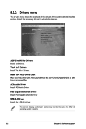
... Gigabit Ethernet Driver USB 2.0 Driver Installl the USB 2.0 driver.. 5.2.2 Drivers menu The drivers menu shows the available device drivers if the system detects installed devices. ASUS InstAll for Drivers InstAll for different operating system versions. 5-2 Chapter 5: Software support Allow you to browse the path \Drivers...
... Gigabit Ethernet Driver USB 2.0 Driver Installl the USB 2.0 driver.. 5.2.2 Drivers menu The drivers menu shows the available device drivers if the system detects installed devices. ASUS InstAll for Drivers InstAll for different operating system versions. 5-2 Chapter 5: Software support Allow you to browse the path \Drivers...
P5VD1-X User's Manual for English Edition
Page 99
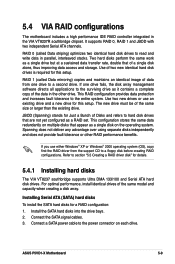
... install the SATA hard disks for details. 5.4.1 Installing hard disks The VIA VT8237 southbridge supports Ultra DMA 133/100 and Serial ATA hard disk drives. ASUS P5VD1-X Motherboard 5-9 Install the SATA hard disks into the drive bays. 2. For optimal performance, install identical drives of the same size or larger than the existing...ts. JBOD (Spanning) stands for this setup. RAID 0 (called Data mirroring) copies and maintains an identical image of the data in the VIA VT8237R southbridge chipset. The new drive must be of the same model and capacity when creating a disk array.
... install the SATA hard disks for details. 5.4.1 Installing hard disks The VIA VT8237 southbridge supports Ultra DMA 133/100 and Serial ATA hard disk drives. ASUS P5VD1-X Motherboard 5-9 Install the SATA hard disks into the drive bays. 2. For optimal performance, install identical drives of the same size or larger than the existing...ts. JBOD (Spanning) stands for this setup. RAID 0 (called Data mirroring) copies and maintains an identical image of the data in the VIA VT8237R southbridge chipset. The new drive must be of the same model and capacity when creating a disk array.

P5VD1-X User's Manual for English Edition
Page 100
...-left corner of the screen are replaced with create array menu options. From the Advanced > I/O Device Configuration menu in the VIA VT8237R southbridge chipset. VT8237 Series SATA RAID BIOS Ver x.xx Auto Setup For Data Security Array Mode RAID 1 (Mirroring) Select Disk Drives Start Create Process Create a RAID array...
...-left corner of the screen are replaced with create array menu options. From the Advanced > I/O Device Configuration menu in the VIA VT8237R southbridge chipset. VT8237 Series SATA RAID BIOS Ver x.xx Auto Setup For Data Security Array Mode RAID 1 (Mirroring) Select Disk Drives Start Create Process Create a RAID array...

