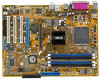
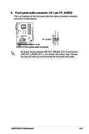
P5VD1-X User's Manual for English Edition
Page 14
Chapter Summary 1.1 Welcome 1-1 1.2 Package contents 1-1 1.3 Special features 1-2 ASUS P5VD1-X Motherboard
P5VD1-X User's Manual for English Edition
Page 15
... the following items. Motherboard ASUS P5VD1-X motherboard Cables 1 x Serial ATA signal cable 1 x Serial ATA power cable 1 x Ultra DMA 133/100/66 cable 1 x FDD cable Accessories I/O shield Application CDs ASUS Motherboard Support CD Documentation User guide If any of ASUS quality motherboards! The motherboard ...the items in the long line of the above items is damaged or missing, contact your motherboard package for buying an ASUS® P5VD1-X motherboard! Thank you start installing the motherboard, and hardware devices on it another standout in your package with the list...
P5VD1-X User's Manual for English Edition
Page 17
This motherboard provides excellent compatibility and flexibility by supporting either 64-bit or 32-bit architecture. ASUS P5VD1-X Motherboard 1-3 Dual-Core CPU Enjoy the extraordinary CPU power from the 12 Mbps bandwidth on USB 1.1 to a fast 480 Mbps on the rear panel. The S/...
P5VD1-X User's Manual for English Edition
Page 20
Chapter Summary 2.1 Before you proceed 2-1 2.2 Motherboard overview 2-2 2.3 Central Processing Unit (CPU 2-4 2.4 System memory 2-9 2.5 Expansion slots 2-13 2.6 Jumpers 2-16 2.7 Connectors 2-18 ASUS P5VD1-X Motherboard
P5VD1-X User's Manual for English Edition
Page 21
... that the system is ON, in sleep mode, or in soft-off or the power cord is switched off mode. P5VD1-X ® P5VD1-X Onboard LED SB_PWR ON Standby Power OFF Powered Off ASUS P5VD1-X Motherboard 2-1 This is a reminder that the ATX power supply is detached from the wall socket before touching any component. •...
P5VD1-X User's Manual for English Edition
Page 25
.... 4. Lift the load lever in the direction of the arrow to the socket pins, do not remove the PnP cap unless you . Gold triangle mark ASUS P5VD1-X Motherboard A 2-5 The socket alignment key should face you are installing a CPU. 3. Press the load lever with your thumb (A) and move it is released from the...
P5VD1-X User's Manual for English Edition
Page 27
... fan. 1. Place the heatsink on the motherboard. Follow these steps to the chassis before you install the heatsink and fan assembly. Push pin Motherboard hole ASUS P5VD1-X Motherboard 2-7 If you buy a boxed Intel® Pentium® 4 processor, the package includes the CPU fan and heatsink assembly. If you buy a CPU separately, make...
P5VD1-X User's Manual for English Edition
Page 29
ASUS P5VD1-X Motherboard 2-9 The following figure illustrates the location of the recommended configurations in this motherboard. Use any of the sockets: DIMM_A1 DIMM_A2 DIMM_B1 DIMM_B2 P5VD1-X ® P5VD1-X 184-pin DDR DIMM sockets 2.4.2 Memory Configurations You may cause memory sizing error or system boot failure. 2.4 System memory 2.4.1 Overview The motherboard...
P5VD1-X User's Manual for English Edition
Page 31
... of modules inserted into either slot, in a Single-channel memory configuration. SS - B - supports on pair of Dualchannel memory configuration. Double-sided ASUS P5VD1-X Motherboard 2-11 C - DDR400 Qualified Vendors List Size 256MB 512MB 256MB 512MB 256MB 256MB 512MB 512MB 256MB 256MB 512MB 256MB 512MB 512MB 512MB 256MB...
P5VD1-X User's Manual for English Edition
Page 33
... the tables on BIOS setup. 2. Secure the card to the chassis with the slot and press firmly until the card is already installed in a chassis). 3. ASUS P5VD1-X Motherboard 2-13 Replace the system cover. 2.5.2 Configuring an expansion card After installing the expansion card, configure it and make the necessary...
P5VD1-X User's Manual for English Edition
Page 35
...;gure shows a graphics card installed on a PCI slot. 2.5.5 AGP slot The Accelerated Graphics Port (AGP) slot supports AGP 8X/4X (+1.5V) cards. ASUS P5VD1-X Motherboard 2-15 2.5.4 PCI slots The PCI slots support cards such as a LAN card, SCSI card, USB card, and other cards that you buy an...shows a LAN card installed on the universal PCI Express x16 slot. Install only +1.5V or +0.8V AGP cards. When you ask for 1.5v P5VD1-X Accelerated Graphics Port (AGP) 2.5.6 Universal PCI Express x16 slot This motherboard supports universal PCI Express x16 graphic cards that they fit the AGP...
P5VD1-X User's Manual for English Edition
Page 37
...Gigabyte GV-NX66T128D (BIOS: V5.43.02.16) Pass Pass Leadtek WinFast PX6600GT TDH Rev. ASUS P5VD1-X Motherboard 2-17 VGA Qualified Vender List PCIe X 16 VGA Card MSI NX6600GT-TD128E PCIe _ 4X PCIe X 16 VGA Card ASUS EN6600 Rev.V200 (BIOS: V5.43.02.16) Pass Rev V1.00A (BIOS: V5... Rev. A (BIOS: V5.43.02.16) Albatron PC6200 (BIOS: V5.43.02.27) ASUS EN6800ULTRA (BIOS: V5.40.02.32.AS07) Pass ASUS EAX700 (BIOS: V5E4D.9.7.1.3. PN:109-A31900-00 (BIOS: V5d57.9.3.1.20) Pass ASUS EAX850PRO (BIOS: V5D4F.9.7.1.4.AS02) PCIe _ 4X Pass Pass Pass Pass Pass Pass *Note: Some PCI Express ...
P5VD1-X User's Manual for English Edition
Page 39
... wake up +5V (Default) +5VSB • The USB device wake-up the computer from S3 and S4 sleep modes (no power to additional USB ports. ASUS P5VD1-X Motherboard 2-19 The USBPWR56 and USBPWR78 jumper is for each USB port; otherwise, the system would not power up from S1 sleep mode (CPU stopped...
P5VD1-X User's Manual for English Edition
Page 41
... Serial Bus (USB) ports are available for connecting USB 2.0 devices. 9. Serial connector. This port connects an external audio output device via a coaxial S/PDIF cable. 11. ASUS P5VD1-X Motherboard 2-21 PS/2 keyboard port (purple). USB 2.0 ports 3 and 4. This 9-pin COM1 port is for serial devices. 10.
P5VD1-X User's Manual for English Edition
Page 43
... 8237/8237R Southbridge chipsets do not provide forwards compatibility with SATA-II hard disk drives at 300MB/s. ASUS P5VD1-X Motherboard 2-23 If you can create a RAID 0 or RAID 1 configuration through the onboard VIA® VT8237R RAID controller.... P5VD1-X ® SATA1 SATA2 GND RSATA_TXP1 RSATA_TXN1 GND RSATA_RXP1 RSATA_RXN1 GND GND RSATA_TXP2 RSATA_TXN2 GND RSATA_RXP2 RSATA_RXN2 GND P5VD1-X SATA connectors Important notes on creating a RAID configuration. Serial ATA connectors ...
P5VD1-X User's Manual for English Edition
Page 45
... power connectors +3 Volts +3 Volts Ground +5 Volts +5 Volts +5 Volts -5 Volts Ground Ground Ground PSON# Ground -12 Volts +3 Volts ASUS P5VD1-X Motherboard 2-25 ATX power connectors (24-pin EATXPWR, 4-pin ATX12V) These connectors are designed to use a PSU with 20-pin and 4-pin power plugs, make ...
P5VD1-X User's Manual for English Edition
Page 47
9. Remove the caps only when you are shorted with jumper caps. ASUS P5VD1-X Motherboard 2-27 AGND +5VA BLINE_OUT_R BLINE_OUT_L P5VD1-X ® FP_AUDIO MIC2 MICPWR Line out_R NC Line out_L P5VD1-X Front panel audio connector Be default, the pins labeled LINE OUT_R/BLINE_OUT_R and the pins LINE OUT_L/BLINE_OUT_L are connecting the front panel audio cable. Front panel audio connector (10-1 pin FP_AUDIO) This is an interface for the front panel cable that allows convenient connection and control of audio devices.
P5VD1-X User's Manual for English Edition
Page 50
Chapter Summary 3.1 Starting up for the first time 3-1 3.2 Powering off the computer 3-2 ASUS P5VD1-X Motherboard
P5VD1-X User's Manual for English Edition
Page 51
... system LED turns on the devices in Chapter 4. While the tests are off. 3. For systems withATX power supplies, the system LED lights up for assistance. ASUS P5VD1-X Motherboard 3-1 Connect the power cord to the power connector at the back of the system chassis. 4.
P5VD1-X User's Manual for English Edition
Page 54
Chapter Summary 4.1 Managing and updating your BIOS 4-1 4.2 BIOS setup program 4-10 4.3 Main menu 4-13 4.4 Advanced menu 4-16 4.5 Power menu 4-25 4.6 Boot menu 4-29 4.7 Exit menu 4-33 ASUS P5VD1-X Motherboard