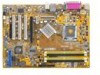
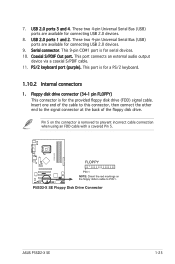
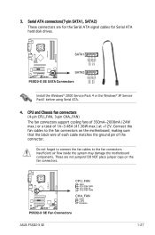
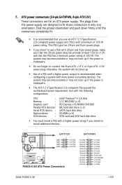
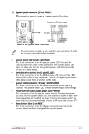
Motherboard Installation Guide
Page 13
This chapter describes the motherboard features and the new technologies it supports. 1Product introduction ASUS P5SD2-X SE 1-1
Motherboard Installation Guide
Page 14
...-pin surface mount Land Grid Array (LGA) socket designed for the following items. Motherboard Cables Accessories Application CDs Documentation ASUS P5SD2-X SE motherboard 1 x Serial ATA signal cable 1 x Serial ATA power cable 1 x Ultra DMA 133/100/66 cable 1 x Floppy disk drive cable...Intel® Pentium® 4/Intel® Pentium® D /Intel® Celeron /Celeron D processors. See page 1-8 for buying an ASUS® P5SD2-X SE motherboard! 1.1 Welcome! Thank you start installing the motherboard, and hardware devices on it another standout in the long line of the above items...
Motherboard Installation Guide
Page 15
...). The SATA specification allows for faster and more flexible cables with peak bandwidths of the latest 3D graphics, multimedia, and Internet applications. ASUS P5SD2-X SE 1-3 The dual-channel DDR2 architecture doubles the bandwidth of system memory for thinner, more efficient computing. DDR2 memory support The motherboard supports DDR2...
Motherboard Installation Guide
Page 17
... in soft-off or the power cord is switched off mode. 1.4 Before you proceed Take note of the onboard LED. P5SD2-X SE ® P5SD2-X SE Onboard LED SB_PWR ON Standby Power OFF Powered Off ASUS P5SD2-X SE 1-5 Failure to do so may cause severe damage to avoid touching the ICs on them. • Whenever you uninstall any...
Motherboard Installation Guide
Page 21
... the PnP cap unless you . Load plate 5. Lift the load plate with your thumb and forefinger to a 135º angle. 4. Gold triangle mark ASUS P5SD2-X SE A 1-9 The socket alignment key should face you are installing a CPU. 3. Press the load lever with your thumb (A) and move it is on the bottom-left...
Motherboard Installation Guide
Page 23
... installed CPU, making sure that a Thermal Interface Material is oriented as shown, with the narrow groove directed outward. To install the CPU heatsink and fan: 1. ASUS P5SD2-X SE 1-11 1.6.2 Installing the CPU heatsink and fan The Intel® Pentium® 4 LGA775 processor requires a specially designed heatsink and fan assembly to ensure optimum thermal...
Motherboard Installation Guide
Page 25
Rotate each fastener counterclockwise. 3. Pull up two fasteners at a time in a diagonal sequence B to disengage the heatsink and fan assembly from the connector on the motherboard. 2. Disconnect the CPU fan cable from the A A motherboard. B A B B A ASUS P5SD2-X SE 1-13 1.6.3 Uninstalling the CPU heatsink and fan To uninstall the CPU heatsink and fan: 1.
Motherboard Installation Guide
Page 27
...by the system. • Always install DIMMs with four 240-pin Double Data Rate 2 (DDR2) Dual Inline Memory Modules (DIMM) sockets. ASUS P5SD2-X SE 1-15 For optimum compatibility, it is recommended that you obtain memory modules from the same vendor. • Due to chipset limitation, this ...motherboard supports a maximum of the sockets: P5SD2-X SE DIMM_A1 DIMM_A2 DIMM_B1 DIMM_B2 ® P5SD2-X SE 240-pin DDR2 DIMM Sockets 1.7.2 Memory Configurations You may install 256 MB, 512 MB and 1 GB unbuffered...
Motherboard Installation Guide
Page 29
..., in a Single-channel memory configuration. supports two pairs of Dual-channel memory configuration. Visit the ASUS website (www.asus.com) for the latest DDR2- 533 Qualified Vendors List. C - ASUS P5SD2-X SE 1-17 Double Sided DIMM Support: A - Single Sided DS - B - Size 512MB 256MB 512MB 512MB 1024MB 1024MB 512MB 256MB 256MB...
Motherboard Installation Guide
Page 31
... cover. 1.8.2 Configuring an expansion card After installing the expansion card, configure it and make the necessary hardware settings for later use . ASUS P5SD2-X SE 1-19 1.8 Expansion slots In the future, you may need to do so may cause you physical injury and damage motherboard components. 1.8.1 Installing an expansion card...
Motherboard Installation Guide
Page 33
... a graphics card installed on a PCI slot. 1.8.5 PCI Express x16 slot This motherboard supports PCI Express x16 graphic cards that comply with PCI specifications. ASUS P5SD2-X SE 1-21 1.8.4 PCI slots The PCI slots support cards such as a LAN card, SCSI card, USB card, and other cards that comply with the PCI Express...
Motherboard Installation Guide
Page 35
... USB connectors that can connect to CPU, DRAM in slow refresh, power supply in reduced power mode). USBPW12 USBPW34 12 23 P5SD2-X SE +5V (Default) +5VSB USBPW78 USBPW56 ® 12 23 +5V P5SD2-X SE USB Device Wake-Up (Default) +5VSB • The USB device wake-up from S1 sleep mode (CPU stopped, DRAM refreshed... ports. Set to +5VSB to wake up feature requires a power supply that you can provide 500mA on the +5VSB lead for the rear USB ports. ASUS P5SD2-X SE 1-23 2. The USBPWR12 and USBPWR34 jumpers are for each USB port;
Motherboard Installation Guide
Page 37
... the floppy disk drive. FLOPPY PIN 1 ® NOTE: Orient the red markings on the connector is for a PS/2 keyboard. 1.10.2 Internal connectors 1. P5SD2-X SE Floppy Disk Drive Connector P5SD2-X SE ASUS P5SD2-X SE 1-25 Coaxial S/PDIF Out port. Floppy disk drive connector (34-1 pin FLOPPY) This connector is removed to prevent incorrect cable connection when using...
Motherboard Installation Guide
Page 39
... the ground pin of 1A~3.48A (41.36W max.) at +12V. P5SD2-X SE CPU_FAN GND CPU FAN PWR CPU FAN IN CPU FAN PWM CHA_FAN GND ® +12V Rotation P5SD2-X SE Fan Connectors ASUS P5SD2-X SE 1-27 Do not forget to connect the fan cables to the fan connectors... on the fan connectors. P5SD2-X SE GND RSATA_RXP2 RSATA_RXN2 GND RSATA_TXN2 RSATA_TXP2 GND GND RSATA_TXP1 RSATA_TXN1 GND RSATA_RXN1 RSATA_RXP1...
Motherboard Installation Guide
Page 41
... PSON# Ground Ground Ground -5 Volts +5 Volts +5 Volts +5 Volts Ground +3 Volts +3 Volts Ground +5 Volts Ground +5 Volts Ground Power OK +5V Standby +12 Volts +12 Volts +3 Volts ASUS P5SD2-X SE 1-29 7. ATX power connectors (24-pin EATXPWR, 8-pin ATX12V) These connectors are designed to use an ATX 12 V Specification 2.0-compliant power supply unit...
Motherboard Installation Guide
Page 43
10. PLED SPEAKER PLED+ PLED+5V Ground Ground Speaker P5SD2-X SE PANEL ® IDE_LED P5SD2-X SE System Panel Connector IDE_LED+ IDE_LED- The IDE LED lights up when you to this connector. Pressing the power button turns the system ON or puts ... to the connector description below for details. • System power LED (Green 3-pin PLED) This 3-pin connector is color-coded for the HDD Activity LED. ASUS P5SD2-X SE 1-31 Connect the chassis power LED cable to hear system beeps and warnings. • Power/Soft-off button (Light green 2-pin PWRSW) This connector is...
Motherboard Installation Guide
Page 45
Detailed descriptions of the BIOS parameters are also provided. 2 BIOS setup ASUS P5SD2-X SE 2-1 This chapter tells how to change the system settings through the BIOS Setup menus.
Motherboard Installation Guide
Page 47
...in the BIOS chip so it is accessible by pressing + during POST to a floppy disk, then restart the system. 3. Visit the ASUS website (www.asus.com) to go through the long process of booting from a floppy disk and using EZ Flash: 1. Start erasing....... Press + during...64257;le for floppy... error message appears if there is not found !" Make sure that contains the BIOS file to continue. 2. ASUS P5SD2-X SE 2-3 The EZ Flash utility is built-in the drive. To update the BIOS using a DOS-based utility. Completed. Press , then follow screen ...
Motherboard Installation Guide
Page 49
...;lename on the bootable floppy disk. Version 1.10 Copyright (C) 2002 American Megatrends, Inc. done Reading flash .... All rights reserved. done Erasing flash .... A:\> ASUS P5SD2-X SE 2-5 A:\>afudos /iP5SD2XS.ROM AMI Firmware Update Utility - done Advanced check ... done Please restart your computer. A:\>afudos /iP5SD2XSE.ROM 4. Reading file ..... Reboot the system from...
Motherboard Installation Guide
Page 51
.... Checking for this motherboard. CD-ROM found ! The recovered BIOS may not be the latest BIOS version for floppy... Visit the ASUS website (www.asus.com) to the optical drive. 3. ASUS P5SD2-X SE 2-7 Start flashing... DO NOT shut down or reset the system while updating the BIOS! Starting BIOS recovery... Floppy not found !