
Motherboard Installation Guide
Page 13
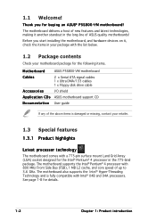
This chapter describes the motherboard features and the new technologies it supports. 1Product introduction ASUS P5S800-VM 1-1
This chapter describes the motherboard features and the new technologies it supports. 1Product introduction ASUS P5S800-VM 1-1
Motherboard Installation Guide
Page 14
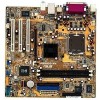
...motherboard comes with Intel® 04B and 04A processors. The motherboard delivers a host of ASUS quality motherboards! See page 1-8 for buying an ASUS® P5S800-VM motherboard! The motherboard supports the Intel® Pentium® 4 processor with 800 MHz ...775-pin surface mount Land Grid Array (LGA) socket designed for the following items. Motherboard ASUS P5S800-VM motherboard Cables 2 x Serial ATA signal cables 1 x Ultra DMA/133 cables 1 x Floppy disk drive cable Accessories I/O shield A p p l i c a t i o n C D s ASUS motherboard support CD D o c u m e n t a t i o n ...
...motherboard comes with Intel® 04B and 04A processors. The motherboard delivers a host of ASUS quality motherboards! See page 1-8 for buying an ASUS® P5S800-VM motherboard! The motherboard supports the Intel® Pentium® 4 processor with 800 MHz ...775-pin surface mount Land Grid Array (LGA) socket designed for the following items. Motherboard ASUS P5S800-VM motherboard Cables 2 x Serial ATA signal cables 1 x Ultra DMA/133 cables 1 x Floppy disk drive cable Accessories I/O shield A p p l i c a t i o n C D s ASUS motherboard support CD D o c u m e n t a t i o n ...

Motherboard Installation Guide
Page 15
...® ALC655 audio CODEC that smartly manages data streaming between the Northbridge and Southbridge, memory, graphics interface, and other peripherals for efficient and superior performance. ASUS P5S800-VM 1-3 See page 1-25 for details. SIS Ultra-AGPII™ Technology Outstanding graphics performance is backward compatible with digital connectivity to a fast 480 Mbps on USB...
...® ALC655 audio CODEC that smartly manages data streaming between the Northbridge and Southbridge, memory, graphics interface, and other peripherals for efficient and superior performance. ASUS P5S800-VM 1-3 See page 1-25 for details. SIS Ultra-AGPII™ Technology Outstanding graphics performance is backward compatible with digital connectivity to a fast 480 Mbps on USB...

Motherboard Installation Guide
Page 17
... object or to a metal object, such as the power supply case, before removing or plugging in soft-off or the p o w e r c o r d i s d e t a c h e d f r o m t h e p o w e r s u p p l y . P5S800-VM ® P5S800-VM Onboard LED SB_PWR1 ON Standby Power OFF Powered Off ASUS P5S800-VM 1-5 Failure to do so may cause severe damage to the motherboard, peripherals, and/or components. Onboard LED The motherboard comes...
... object or to a metal object, such as the power supply case, before removing or plugging in soft-off or the p o w e r c o r d i s d e t a c h e d f r o m t h e p o w e r s u p p l y . P5S800-VM ® P5S800-VM Onboard LED SB_PWR1 ON Standby Power OFF Powered Off ASUS P5S800-VM 1-5 Failure to do so may cause severe damage to the motherboard, peripherals, and/or components. Onboard LED The motherboard comes...

Motherboard Installation Guide
Page 19
1.5.3 Motherboard layout PS/2KBMS KBPWR1 T: Mouse B: Keyboard ATX12V1 COM1 LGA775 CPU_FAN1 Super I/O Intel FWH 4Mb FLOPPY1 DDR DIMM1 (64 bit,184-pin module) DDR DIMM2 (64 bit,184-pin module) PARALLEL PORT VGA1 F_USB12 LAN_USB34 Top:Line In Center:Line Out Below:Mic In ALC655 FP_AUDIO RTL8100C SiS 661FX AGP1 PCI1 PCI2 PCI3 AUX1 CD1 SPDIF1 P5S800-VM ® SiS 964 CR2032 3V Lithium Cell CMOS Power SB_PWR1 SATA2 SATA1 CLRTC1 PLED1 IR_CON1 USB56 CHA_FAN1 CHASSIS1 USB78 GAME1 SPEAKER1 F_PANEL COM2 SEC_IDE1 PRI_IDE1 ATXPWR1 ASUS P5S800-VM 1-7
1.5.3 Motherboard layout PS/2KBMS KBPWR1 T: Mouse B: Keyboard ATX12V1 COM1 LGA775 CPU_FAN1 Super I/O Intel FWH 4Mb FLOPPY1 DDR DIMM1 (64 bit,184-pin module) DDR DIMM2 (64 bit,184-pin module) PARALLEL PORT VGA1 F_USB12 LAN_USB34 Top:Line In Center:Line Out Below:Mic In ALC655 FP_AUDIO RTL8100C SiS 661FX AGP1 PCI1 PCI2 PCI3 AUX1 CD1 SPDIF1 P5S800-VM ® SiS 964 CR2032 3V Lithium Cell CMOS Power SB_PWR1 SATA2 SATA1 CLRTC1 PLED1 IR_CON1 USB56 CHA_FAN1 CHASSIS1 USB78 GAME1 SPEAKER1 F_PANEL COM2 SEC_IDE1 PRI_IDE1 ATXPWR1 ASUS P5S800-VM 1-7

Motherboard Installation Guide
Page 21
The socket alignment key should face you are installing a CPU. 3. Gold triangle mark ASUS P5S800-VM A 1-9 Lift the load lever in the direction of the arrow to the left corner of the cam box should fit A l i g n m e n t k e y into the CPU notch. Press ...
The socket alignment key should face you are installing a CPU. 3. Gold triangle mark ASUS P5S800-VM A 1-9 Lift the load lever in the direction of the arrow to the left corner of the cam box should fit A l i g n m e n t k e y into the CPU notch. Press ...

Motherboard Installation Guide
Page 23
... buy a CPU separately, make sure that a Thermal Interface Material is oriented as shown, with the narrow groove directed outward. Place the heatsink on the motherboard. ASUS P5S800-VM 1-11 If you purchased a separate CPU heatsink and fan assembly, make sure that the four fasteners match the holes on top of the installed CPU...
... buy a CPU separately, make sure that a Thermal Interface Material is oriented as shown, with the narrow groove directed outward. Place the heatsink on the motherboard. ASUS P5S800-VM 1-11 If you purchased a separate CPU heatsink and fan assembly, make sure that the four fasteners match the holes on top of the installed CPU...

Motherboard Installation Guide
Page 25
Disconnect the CPU fan cable from the A A motherboard. 1.6.3 Uninstalling the CPU heatsink and fan To uninstall the CPU heatsink and fan: 1. Rotate each fastener counterclockwise. 3. B A B B A ASUS P5S800-VM 1-13 Pull up two fasteners at a time in a diagonal sequence to disengage the heatsink B and fan assembly from the connector on the motherboard labeled CPU_FAN1. 2.
Disconnect the CPU fan cable from the A A motherboard. 1.6.3 Uninstalling the CPU heatsink and fan To uninstall the CPU heatsink and fan: 1. Rotate each fastener counterclockwise. 3. B A B B A ASUS P5S800-VM 1-13 Pull up two fasteners at a time in a diagonal sequence to disengage the heatsink B and fan assembly from the connector on the motherboard labeled CPU_FAN1. 2.

Motherboard Installation Guide
Page 27
...SS VS32M8-5 2B0409 •• Value select DS VS32M8-5 2B0412 •• Samsung SS K4H5608380-TCB3 •• (Continued on the next page) ASUS P5S800-VM 1-15 You may install 128 MB, 256 MB, 512 MB and 1 GB unbuffered non-ECC DDR DIMMs into the DIMM sockets. 1.7 System memory ...; DIMM1 DIMM2 P5S800-VM 184-pin DDR DIMM sockets 1.7.2 DDR Qualified Vendors List The following table lists the memory modules that have been tested and qualified for this motherboard. Visit the ASUS website (www.asus.com) for the latest DDR DIMM modules for use with two 184-pin Double ...
...SS VS32M8-5 2B0409 •• Value select DS VS32M8-5 2B0412 •• Samsung SS K4H5608380-TCB3 •• (Continued on the next page) ASUS P5S800-VM 1-15 You may install 128 MB, 256 MB, 512 MB and 1 GB unbuffered non-ECC DDR DIMMs into the DIMM sockets. 1.7 System memory ...; DIMM1 DIMM2 P5S800-VM 184-pin DDR DIMM sockets 1.7.2 DDR Qualified Vendors List The following table lists the memory modules that have been tested and qualified for this motherboard. Visit the ASUS website (www.asus.com) for the latest DDR DIMM modules for use with two 184-pin Double ...

Motherboard Installation Guide
Page 29
... and the components. 1. Locked Retaining Clip 1.7.4 Removing a DIMM Follow these steps to unlock the DIMM. 1 1 DDR DIMM notch Support the DIMM lightly with extra force. 2. ASUS P5S800-VM 1-17 Failure to do so may cause severe damage to avoid damaging the DIMM. 3. Remove the DIMM from the socket. DO NOT force a DIMM into...
... and the components. 1. Locked Retaining Clip 1.7.4 Removing a DIMM Follow these steps to unlock the DIMM. 1 1 DDR DIMM notch Support the DIMM lightly with extra force. 2. ASUS P5S800-VM 1-17 Failure to do so may cause severe damage to avoid damaging the DIMM. 3. Remove the DIMM from the socket. DO NOT force a DIMM into...

Motherboard Installation Guide
Page 31
... using PCI cards on shared slots, ensure that the drivers support "Share IRQ" or that the cards do not need IRQ assignments. shared - - - -- - -- shared - - - shared - - - ASUS P5S800-VM 1-19 shared - - --
... using PCI cards on shared slots, ensure that the drivers support "Share IRQ" or that the cards do not need IRQ assignments. shared - - - -- - -- shared - - - shared - - - ASUS P5S800-VM 1-19 shared - - --
Motherboard Installation Guide
Page 33
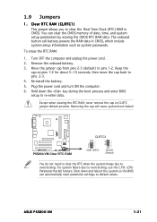
... not need to clear the RTC when the system hangs due to pins 1-2. Keep the cap on CLRTC jumper default position. Re-install the battery. 5. ASUS P5S800-VM 1-21 1.9 Jumpers 1. Move the jumper cap from pins 2-3 (default) to overclocking. For system failure due to clear the Real Time Clock (RTC) RAM in CMOS...
... not need to clear the RTC when the system hangs due to pins 1-2. Keep the cap on CLRTC jumper default position. Re-install the battery. 5. ASUS P5S800-VM 1-21 1.9 Jumpers 1. Move the jumper cap from pins 2-3 (default) to overclocking. For system failure due to clear the Real Time Clock (RTC) RAM in CMOS...

Motherboard Installation Guide
Page 35
... 2-channel Line In Line Out Mic In 4-channel Front Speaker Out Rear Speaker Out Mic In 6-channel Front Speaker Out Rear Speaker Out Center/Subwoofer 7 . U S B 2 . 0 p o r t s 1 a n d 2 . U S B 2 . 0 p o r t s 3 a n d 4 . P S / 2 k e y b o a r d p o r t ( p u r p l e ) . L i n e O u t p o r t ( l i m e ) . S e r i a l c o n n e c t o r . ASUS P5S800-VM 1-23 This port connects a tape, CD, DVD player, or other audio sources. This port is for a PS/2 keyboard. This port connects a headphone or a speaker. L i n e I n p o r t ( l i g h t b l u e ) . In...
... 2-channel Line In Line Out Mic In 4-channel Front Speaker Out Rear Speaker Out Mic In 6-channel Front Speaker Out Rear Speaker Out Center/Subwoofer 7 . U S B 2 . 0 p o r t s 1 a n d 2 . U S B 2 . 0 p o r t s 3 a n d 4 . P S / 2 k e y b o a r d p o r t ( p u r p l e ) . L i n e O u t p o r t ( l i m e ) . S e r i a l c o n n e c t o r . ASUS P5S800-VM 1-23 This port connects a tape, CD, DVD player, or other audio sources. This port is for a PS/2 keyboard. This port connects a headphone or a speaker. L i n e I n p o r t ( l i g h t b l u e ) . In...

Motherboard Installation Guide
Page 37
P5S800-VM ® SPEAKER1 P5S800-VM Speaker out connector Speak Out GND GND +5V 1 ASUS P5S800-VM 1-25 If you installed Serial ATA hard disk drives, you to hear system beeps and warnings. Speaker connector (4-pin SPEAKER1) This 4-pin connector is available ...
P5S800-VM ® SPEAKER1 P5S800-VM Speaker out connector Speak Out GND GND +5V 1 ASUS P5S800-VM 1-25 If you installed Serial ATA hard disk drives, you to hear system beeps and warnings. Speaker connector (4-pin SPEAKER1) This 4-pin connector is available ...

Motherboard Installation Guide
Page 39
... supply. The system power LED lights up when you turn on this motherboard. • Do not forget to fit these connectors in sleep mode. P5S800-VM ® P5S800-VM PLED connector ASUS P5S800-VM PLED1 PLEDNC PLED+ 1 1-27 otherwise, the system will not boot up if the power is recommended when configuring a system with a higher power output...
... supply. The system power LED lights up when you turn on this motherboard. • Do not forget to fit these connectors in sleep mode. P5S800-VM ® P5S800-VM PLED connector ASUS P5S800-VM PLED1 PLEDNC PLED+ 1 1-27 otherwise, the system will not boot up if the power is recommended when configuring a system with a higher power output...

Motherboard Installation Guide
Page 41
... standard. AGND +5VA BLINE_OUT_R BLINE_OUT_L P5S800-VM ® MIC2 MICPWR Line out_R NC Line out_L 11. COM2 PIN 1 P5S800-VM Serial port connector The Serial port module is for a chassis-mounted front panel audio I /O module cable to this connector, then install the module to this connector. FP_AUDIO1 P5S800-VM Front panel audio connector 12. P5S800-VM ® ASUS P5S800-VM 1-29
... standard. AGND +5VA BLINE_OUT_R BLINE_OUT_L P5S800-VM ® MIC2 MICPWR Line out_R NC Line out_L 11. COM2 PIN 1 P5S800-VM Serial port connector The Serial port module is for a chassis-mounted front panel audio I /O module cable to this connector, then install the module to this connector. FP_AUDIO1 P5S800-VM Front panel audio connector 12. P5S800-VM ® ASUS P5S800-VM 1-29
Motherboard Installation Guide
Page 43
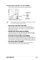
... when data is for the system power button. System panel connector (10-1 pin F_PANEL1) This connector supports several chassis-mounted functions. ASUS P5S800-VM 1-31 The IDE LED lights up when you turn on the BIOS settings. Pressing the power switch for more than four seconds while...chassis power LED cable to this connector. Connect the HDD Activity LED cable to this connector. 14. PLED+ PLEDPWR GND P5S800-VM ® PLED PWRBTN* F_PANEL1 HDLED+ HDLEDGround Reset P5S800-VM System panel connector HDLED RESET The sytem panel connector is for the HDD Activity LED.
... when data is for the system power button. System panel connector (10-1 pin F_PANEL1) This connector supports several chassis-mounted functions. ASUS P5S800-VM 1-31 The IDE LED lights up when you turn on the BIOS settings. Pressing the power switch for more than four seconds while...chassis power LED cable to this connector. Connect the HDD Activity LED cable to this connector. 14. PLED+ PLEDPWR GND P5S800-VM ® PLED PWRBTN* F_PANEL1 HDLED+ HDLEDGround Reset P5S800-VM System panel connector HDLED RESET The sytem panel connector is for the HDD Activity LED.
Motherboard Installation Guide
Page 45
This chapter tells how to change the system settings through the BIOS Setup menus. Detailed descriptions of the BIOS parameters are also provided. 2 BIOS setup ASUS P5S800-VM 2-1
This chapter tells how to change the system settings through the BIOS Setup menus. Detailed descriptions of the BIOS parameters are also provided. 2 BIOS setup ASUS P5S800-VM 2-1

Motherboard Installation Guide
Page 47
...makeboot a: assuming that D: is found, EZ Flash performs the BIOS update process and automatically reboots the system when done. Visit the ASUS website (www.asus.com) to download the latest BIOS file for the motherboard and rename the same to prevent system boot failure! • A "Floppy...for floppy... Press , then follow screen instructions to go through the long process of booting from a floppy disk and using EZ Flash: 1. ASUS P5S800-VM 2-3 d. Save the BIOS file to display the following. Press + during the Power-On Self Tests (POST). Completed. error message appears if...
...makeboot a: assuming that D: is found, EZ Flash performs the BIOS update process and automatically reboots the system when done. Visit the ASUS website (www.asus.com) to download the latest BIOS file for the motherboard and rename the same to prevent system boot failure! • A "Floppy...for floppy... Press , then follow screen instructions to go through the long process of booting from a floppy disk and using EZ Flash: 1. ASUS P5S800-VM 2-3 d. Save the BIOS file to display the following. Press + during the Power-On Self Tests (POST). Completed. error message appears if...

Motherboard Installation Guide
Page 49
... the BIOS. done Erasing flash .... done Writing flash .... 0x0008CC00 (9%) Verifying flash .. A:\>afudos /iP5S800VM.ROM AMI Firmware Update Utility - All rights reserved. done A:\> ASUS P5S800-VM 2-5 Reading file ..... The utility returns to a bootable floppy disk. You need to prevent system boot failure! 5. done Writing flash .... 0x0008CC00 (9%) Do not shut... hard disk drive. done Erasing flash .... Updating the BIOS file To update the BIOS file using the AFUDOS utility: 1. Visit the ASUS website (www.asus.com) and download the latest BIOS file for the motherboard.
... the BIOS. done Erasing flash .... done Writing flash .... 0x0008CC00 (9%) Verifying flash .. A:\>afudos /iP5S800VM.ROM AMI Firmware Update Utility - All rights reserved. done A:\> ASUS P5S800-VM 2-5 Reading file ..... The utility returns to a bootable floppy disk. You need to prevent system boot failure! 5. done Writing flash .... 0x0008CC00 (9%) Do not shut... hard disk drive. done Erasing flash .... Updating the BIOS file To update the BIOS file using the AFUDOS utility: 1. Visit the ASUS website (www.asus.com) and download the latest BIOS file for the motherboard.


