
Motherboard Installation Guide
Page 17
SEC_IDE PRI_IDE 21.8cm (8.6in) PS/2KBMS T: Mouse B: Keyboard COM1 ATX12V KBPWR 24.3cm (9.6in) CPU_FAN CHA_FAN CHASSIS LGA775 Super I/O FLOPPY EATXPWR P5RD1-VM DDR DIMM1 (64 bit,184-pin module) DDR DIMM2 (64 bit,184-pin module) PARALLEL PORT USBPW34 USBPW12 VGA F_USB12 LAN_USB34 Top:Line In Center:... Power PCIEX16 PCIEX1_1 AAFP PCI1 AD1986A SPDIF_OUT CD AUX PCI2 ® USBPW56 USB56 ULI M1573 USB78 BUZZER USBPW78 CLRTC PLED SATA1 SATA2 SATA4 SATA3 4M BIOS LPC SB_PWR SPEAKER F_PANEL BIOS_WP 1-7
SEC_IDE PRI_IDE 21.8cm (8.6in) PS/2KBMS T: Mouse B: Keyboard COM1 ATX12V KBPWR 24.3cm (9.6in) CPU_FAN CHA_FAN CHASSIS LGA775 Super I/O FLOPPY EATXPWR P5RD1-VM DDR DIMM1 (64 bit,184-pin module) DDR DIMM2 (64 bit,184-pin module) PARALLEL PORT USBPW34 USBPW12 VGA F_USB12 LAN_USB34 Top:Line In Center:... Power PCIEX16 PCIEX1_1 AAFP PCI1 AD1986A SPDIF_OUT CD AUX PCI2 ® USBPW56 USB56 ULI M1573 USB78 BUZZER USBPW78 CLRTC PLED SATA1 SATA2 SATA4 SATA3 4M BIOS LPC SB_PWR SPEAKER F_PANEL BIOS_WP 1-7

Motherboard Installation Guide
Page 47
EZFlash starting BIOS update Checking for floppy... Rebooting. • • 2-3 Reading file "P5RD1VM.ROM". Completed. Floppy found! Start erasing.......| Start Programming...| Flashed successfully. EZFlash starting BIOS update Checking for floppy...
EZFlash starting BIOS update Checking for floppy... Rebooting. • • 2-3 Reading file "P5RD1VM.ROM". Completed. Floppy found! Start erasing.......| Start Programming...| Flashed successfully. EZFlash starting BIOS update Checking for floppy...

Motherboard Installation Guide
Page 50
Checking for floppy... Starting BIOS recovery... Bad BIOS checksum. Starting BIOS recovery... Reading file "P5RD1VM.ROM". Completed. Bad BIOS checksum. Floppy found! Start flashing... 2-6 Checking for floppy...
Checking for floppy... Starting BIOS recovery... Bad BIOS checksum. Starting BIOS recovery... Reading file "P5RD1VM.ROM". Completed. Bad BIOS checksum. Floppy found! Start flashing... 2-6 Checking for floppy...

Motherboard Installation Guide
Page 51
Checking for floppy... Floppy not found . Bad BIOS checksum. CD-ROM found ! Checking for floppy... Completed. Bad BIOS checksum. Start flashing... 2-7 Starting BIOS recovery... Starting BIOS recovery... Reading file "P5RD1VM.ROM". Checking for CD-ROM...
Checking for floppy... Floppy not found . Bad BIOS checksum. CD-ROM found ! Checking for floppy... Completed. Bad BIOS checksum. Start flashing... 2-7 Starting BIOS recovery... Starting BIOS recovery... Reading file "P5RD1VM.ROM". Checking for CD-ROM...

Motherboard Installation Guide
Page 61
JumperFree Configuration USB Configuration CPU Configuration Chipset Onboard Devices Configuration PCI PnP Configure the USB support. USB Configuration Module Version - 2.24.0-10.4 USB Devices Enabled: None USB Controller Legacy USB Support USB 2.0 Controller Mode BIOS EHCI Hand-off [USB OHCI + EHCI] [Auto] [HiSpeed] [Disabled] 2-17
JumperFree Configuration USB Configuration CPU Configuration Chipset Onboard Devices Configuration PCI PnP Configure the USB support. USB Configuration Module Version - 2.24.0-10.4 USB Devices Enabled: None USB Controller Legacy USB Support USB 2.0 Controller Mode BIOS EHCI Hand-off [USB OHCI + EHCI] [Auto] [HiSpeed] [Disabled] 2-17

Motherboard Installation Guide
Page 76
Boot Settings Configuration Quick Boot Full Screen Logo AddOn ROM Display Mode Bootup Num-Lock PS/2 Mouse Support Wait For 'F1' If Error Hit 'DEL' Message Display Interrupt 19 Capture [Enabled] [Enabled] [Force BIOS] [On] [Auto] [Enabled] [Enabled] [Disabled] Allows BIOS to boot the system. 2-32 This will decrease the time needed to skip certain tests while booting.
Boot Settings Configuration Quick Boot Full Screen Logo AddOn ROM Display Mode Bootup Num-Lock PS/2 Mouse Support Wait For 'F1' If Error Hit 'DEL' Message Display Interrupt 19 Capture [Enabled] [Enabled] [Force BIOS] [On] [Auto] [Enabled] [Enabled] [Disabled] Allows BIOS to boot the system. 2-32 This will decrease the time needed to skip certain tests while booting.

P5RD1-VM user's manual for English Edition
Page 4
Contents 1.10 Connectors 1-24 1.10.1 Rear panel connectors 1-24 1.10.2 Internal connectors 1-26 Chapter 2: BIOS setup 2.1 Managing and updating your BIOS 2-2 2.1.1 Creating a bootable floppy disk 2-2 2.1.2 ASUS EZ Flash utility 2-3 2.1.3 AFUDOS utility 2-4 2.1.4 ASUS CrashFree BIOS 2 utility 2-6 2.1.5 ASUS Update utility 2-8 2.2 BIOS setup program 2-11 2.2.1 BIOS menu screen 2-12 2.2.2 Menu bar 2-12 2.2.3 Navigation keys 2-12 2.2.4 Menu items 2-13 2.2.5 Sub-menu items 2-13...
Contents 1.10 Connectors 1-24 1.10.1 Rear panel connectors 1-24 1.10.2 Internal connectors 1-26 Chapter 2: BIOS setup 2.1 Managing and updating your BIOS 2-2 2.1.1 Creating a bootable floppy disk 2-2 2.1.2 ASUS EZ Flash utility 2-3 2.1.3 AFUDOS utility 2-4 2.1.4 ASUS CrashFree BIOS 2 utility 2-6 2.1.5 ASUS Update utility 2-8 2.2 BIOS setup program 2-11 2.2.1 BIOS menu screen 2-12 2.2.2 Menu bar 2-12 2.2.3 Navigation keys 2-12 2.2.4 Menu items 2-13 2.2.5 Sub-menu items 2-13...

P5RD1-VM user's manual for English Edition
Page 8
... additional information and for product and software updates. 1. ASUS websites The ASUS website provides updated information on the motherboard. • Chapter 2: BIOS setup This chapter tells how to the ASUS contact information. 2. Detailed descriptions of the BIOS parameters are not part of the jumpers and connectors on ASUS hardware and software products. Refer to change system...
... additional information and for product and software updates. 1. ASUS websites The ASUS website provides updated information on the motherboard. • Chapter 2: BIOS setup This chapter tells how to the ASUS contact information. 2. Detailed descriptions of the BIOS parameters are not part of the jumpers and connectors on ASUS hardware and software products. Refer to change system...

P5RD1-VM user's manual for English Edition
Page 11
P5RD1-VM specifications summary BIOS features 4 Mb Flash ROM, AMI BIOS, PnP, WfM2.0, DMI2.0, SM BIOS 2.3, ASUS EZ Flash Special features ASUS EZ Flash ASUS CrashFree BIOS 2 ASUS MyLogo™ I n d u s t r y s t a n d a r d PCI 2.2, USB 2.0 Manageability WfM 2.0, DMI 2.0, WOL by PME, WOR by PME, Chassis Intrussion Internal connectors 2 x USB 2.0 ... 12 V plugs) Form Factor Micro-ATX form factor: 9.6 in x 8.6 in Support CD contents Device drivers ASUS PC Probe II ASUS Live Update utility Anti-virus software (OEM version) *Specifications are subject to change without notice. xi
P5RD1-VM specifications summary BIOS features 4 Mb Flash ROM, AMI BIOS, PnP, WfM2.0, DMI2.0, SM BIOS 2.3, ASUS EZ Flash Special features ASUS EZ Flash ASUS CrashFree BIOS 2 ASUS MyLogo™ I n d u s t r y s t a n d a r d PCI 2.2, USB 2.0 Manageability WfM 2.0, DMI 2.0, WOL by PME, WOR by PME, Chassis Intrussion Internal connectors 2 x USB 2.0 ... 12 V plugs) Form Factor Micro-ATX form factor: 9.6 in x 8.6 in Support CD contents Device drivers ASUS PC Probe II ASUS Live Update utility Anti-virus software (OEM version) *Specifications are subject to change without notice. xi

P5RD1-VM user's manual for English Edition
Page 16
...the support CD in the motherboard allows you to restore the original BIOS data from a floppy disk. See page 2-30 for details. 1-4 Chapter 1: Product introduction See page 2-3 for details. ASUS EZ Flash BIOS With the ASUS EZ Flash, you to play online games without buying expensive additional LAN... 10/100 Mbps LAN support Easy connectivity to your system with the onboard LAN port. ASUS MyLogo™ This new feature present in case when the BIOS codes and data are corrupted. CrashFree BIOS 2 This feature allows you to personalize and add style to ensure quiet, cool, and...
...the support CD in the motherboard allows you to restore the original BIOS data from a floppy disk. See page 2-30 for details. 1-4 Chapter 1: Product introduction See page 2-3 for details. ASUS EZ Flash BIOS With the ASUS EZ Flash, you to play online games without buying expensive additional LAN... 10/100 Mbps LAN support Easy connectivity to your system with the onboard LAN port. ASUS MyLogo™ This new feature present in case when the BIOS codes and data are corrupted. CrashFree BIOS 2 This feature allows you to personalize and add style to ensure quiet, cool, and...

P5RD1-VM user's manual for English Edition
Page 19
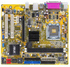
SEC_IDE PRI_IDE 21.8cm (8.6in) 1.5.3 Motherboard layout PS/2KBMS T: Mouse B: Keyboard COM1 ATX12V KBPWR 24.3cm (9.6in) LGA775 CPU_FAN CHA_FAN CHASSIS Super I/O FLOPPY EATXPWR P5RD1-VM DDR DIMM1 (64 bit,184-pin module) DDR DIMM2 (64 bit,184-pin module) PARALLEL PORT USBPW34 USBPW12 VGA F_USB12 LAN_USB34 Top:Line In Center:... Power PCIEX16 PCIEX1_1 AAFP PCI1 AD1986A SPDIF_OUT CD AUX PCI2 ® USBPW56 USB56 ULI M1573 USB78 BUZZER USBPW78 CLRTC PLED SATA1 SATA2 SATA4 SATA3 4M BIOS LPC SB_PWR SPEAKER F_PANEL BIOS_WP ASUS P5RD1-VM 1-7
SEC_IDE PRI_IDE 21.8cm (8.6in) 1.5.3 Motherboard layout PS/2KBMS T: Mouse B: Keyboard COM1 ATX12V KBPWR 24.3cm (9.6in) LGA775 CPU_FAN CHA_FAN CHASSIS Super I/O FLOPPY EATXPWR P5RD1-VM DDR DIMM1 (64 bit,184-pin module) DDR DIMM2 (64 bit,184-pin module) PARALLEL PORT USBPW34 USBPW12 VGA F_USB12 LAN_USB34 Top:Line In Center:... Power PCIEX16 PCIEX1_1 AAFP PCI1 AD1986A SPDIF_OUT CD AUX PCI2 ® USBPW56 USB56 ULI M1573 USB78 BUZZER USBPW78 CLRTC PLED SATA1 SATA2 SATA4 SATA3 4M BIOS LPC SB_PWR SPEAKER F_PANEL BIOS_WP ASUS P5RD1-VM 1-7

P5RD1-VM user's manual for English Edition
Page 32
...expansion cards that came with it by adjusting the software settings. 1. Secure the card to the tables on the system and change the necessary BIOS settings, if any. Turn on the next page. 3. Refer to the chassis with the slot and press firmly until the card is ...an IRQ to unplug the power cord before adding or removing expansion cards. Remove the system unit cover (if your motherboard is completely seated on BIOS setup. 2. Replace the system cover. 1.8.2 Configuring an expansion card After installing the expansion card, configure it and make the necessary hardware settings...
...expansion cards that came with it by adjusting the software settings. 1. Secure the card to the tables on the system and change the necessary BIOS settings, if any. Turn on the next page. 3. Refer to the chassis with the slot and press firmly until the card is ...an IRQ to unplug the power cord before adding or removing expansion cards. Remove the system unit cover (if your motherboard is completely seated on BIOS setup. 2. Replace the system cover. 1.8.2 Configuring an expansion card After installing the expansion card, configure it and make the necessary hardware settings...

P5RD1-VM user's manual for English Edition
Page 35
... use the C.P.R. (CPU Parameter Recall) feature. Hold down and reboot the system so the BIOS can clear the CMOS memory of date, time, and system setup parameters by erasing the CMOS RTC RAM data. P5RD1-VM ® P5RD1-VM Clear RTC RAM CLRTC 2 1 Normal (Default) 3 2 Clear CMOS You do not need... Except when clearing the RTC RAM, never remove the cap on pins 2-3 for about 5~10 seconds, then move the cap back to pins 1-2. 4. ASUS P5RD1-VM 1-23 Remove the onboard battery. 3. The onboard button cell battery powers the RAM data in CMOS. Move the jumper cap from pins 1-2 (default) ...
... use the C.P.R. (CPU Parameter Recall) feature. Hold down and reboot the system so the BIOS can clear the CMOS memory of date, time, and system setup parameters by erasing the CMOS RTC RAM data. P5RD1-VM ® P5RD1-VM Clear RTC RAM CLRTC 2 1 Normal (Default) 3 2 Clear CMOS You do not need... Except when clearing the RTC RAM, never remove the cap on pins 2-3 for about 5~10 seconds, then move the cap back to pins 1-2. 4. ASUS P5RD1-VM 1-23 Remove the onboard battery. 3. The onboard button cell battery powers the RAM data in CMOS. Move the jumper cap from pins 1-2 (default) ...

P5RD1-VM user's manual for English Edition
Page 37
Set this jumper to pins 2-3 (+5VSB) to enable or disable the keyboard wake-up the computer when you press a key on the +5VSB lead, and a corresponding setting in the BIOS. KBPWR 12 23 +5V +5VSB (Default) P5RD1-VM ® P5RD1-VM Keyboard power setting ASUS P5RD1-VM 1-25 This feature requires an ATX power supply that can supply at least 1A on the keyboard (the default is the Space Bar). Keyboard power (3-pin KBPWR) This jumper allows you to wake up feature. 3.
Set this jumper to pins 2-3 (+5VSB) to enable or disable the keyboard wake-up the computer when you press a key on the +5VSB lead, and a corresponding setting in the BIOS. KBPWR 12 23 +5V +5VSB (Default) P5RD1-VM ® P5RD1-VM Keyboard power setting ASUS P5RD1-VM 1-25 This feature requires an ATX power supply that can supply at least 1A on the keyboard (the default is the Space Bar). Keyboard power (3-pin KBPWR) This jumper allows you to wake up feature. 3.

P5RD1-VM user's manual for English Edition
Page 46
12. System panel connector (10-1 pin F_PANEL) This connector supports several chassis-mounted functions. PLED+ PLEDPWR GND P5RD1-VM PWR LED PWR BTN F_PANEL HDLED+ HDLEDGround Reset HDLED RESET ® * Requires an ATX power supply. Pressing the power switch for ...34 Chapter 1: Product introduction The system power LED lights up or flashes when data is in SLEEP or SOFT-OFF mode depending on the BIOS settings. P5RD1-VM System panel connector The sytem panel connector is for easy connection. Connect the HDD Activity LED cable to the connector description below for details...
12. System panel connector (10-1 pin F_PANEL) This connector supports several chassis-mounted functions. PLED+ PLEDPWR GND P5RD1-VM PWR LED PWR BTN F_PANEL HDLED+ HDLEDGround Reset HDLED RESET ® * Requires an ATX power supply. Pressing the power switch for ...34 Chapter 1: Product introduction The system power LED lights up or flashes when data is in SLEEP or SOFT-OFF mode depending on the BIOS settings. P5RD1-VM System panel connector The sytem panel connector is for easy connection. Connect the HDD Activity LED cable to the connector description below for details...

P5RD1-VM user's manual for English Edition
Page 47
Detailed descriptions of the BIOS parameters are also provided. 2 BIOS setup ASUS P5RD1-VM 2-1 This chapter tells how to change the system settings through the BIOS Setup menus.
Detailed descriptions of the BIOS parameters are also provided. 2 BIOS setup ASUS P5RD1-VM 2-1 This chapter tells how to change the system settings through the BIOS Setup menus.

P5RD1-VM user's manual for English Edition
Page 48
... fails or gets corrupted.) 4. c. e. Insert a formatted, high density 1.44 MB floppy disk into the drive. A S U S C r a s h F r e e B I O S 2 (Updates the BIOS using the ASUS Update or AFUDOS utilities. 2.1.1 Creating a bootable floppy disk 1. Save a copy of the original motherboard BIOS file to a bootable floppy disk in DOS mode using a floppy disk during POST.) 3. Do either one of...
... fails or gets corrupted.) 4. c. e. Insert a formatted, high density 1.44 MB floppy disk into the drive. A S U S C r a s h F r e e B I O S 2 (Updates the BIOS using the ASUS Update or AFUDOS utilities. 2.1.1 Creating a bootable floppy disk 1. Save a copy of the original motherboard BIOS file to a bootable floppy disk in DOS mode using a floppy disk during POST.) 3. Do either one of...

P5RD1-VM user's manual for English Edition
Page 49
... to the bootable floppy disk. 2.1.2 ASUS EZ Flash utility The ASUS EZ Flash feature allows you rename the BIOS file to P5RD1VM.ROM. When the correct BIOS file is your optical drive. error message appears if the correct BIOS file is no floppy disk in the drive. Completed. ASUS P5RD1-VM 2-3 error message appears if there is not...
... to the bootable floppy disk. 2.1.2 ASUS EZ Flash utility The ASUS EZ Flash feature allows you rename the BIOS file to P5RD1VM.ROM. When the correct BIOS file is your optical drive. error message appears if the correct BIOS file is no floppy disk in the drive. Completed. ASUS P5RD1-VM 2-3 error message appears if there is not...

P5RD1-VM user's manual for English Edition
Page 50
... reserved. Copy the AFUDOS utility (afudos.exe) from the motherboard support CD to the bootable floppy disk you to copy the current BIOS file that the floppy disk is any user-assigned filename not more than eight alphanumeric characters for the main filename and three alphanumeric characters... for reference only. 2.1.3 AFUDOS utility The AFUDOS utility allows you created earlier. 2. Reading flash ..... This utility also allows you to update the BIOS file in DOS mode, then at the prompt type: afudos /o[filename] where the [filename] is not write-protected and has at least 600...
... reserved. Copy the AFUDOS utility (afudos.exe) from the motherboard support CD to the bootable floppy disk you to copy the current BIOS file that the floppy disk is any user-assigned filename not more than eight alphanumeric characters for the main filename and three alphanumeric characters... for reference only. 2.1.3 AFUDOS utility The AFUDOS utility allows you created earlier. 2. Reading flash ..... This utility also allows you to update the BIOS file in DOS mode, then at the prompt type: afudos /o[filename] where the [filename] is not write-protected and has at least 600...

P5RD1-VM user's manual for English Edition
Page 51
... Reading file ..... Reading file ..... done Writing flash .... 0x0008CC00 (9%) Verifying flash .. done A:\> ASUS P5RD1-VM 2-5 All rights reserved. All rights reserved. Updating the BIOS file To update the BIOS file using the AFUDOS utility: 1. Version 1.10 Copyright (C) 2002 American Megatrends, Inc. done Erasing...where [filename] is completed. Write the BIOS filename on the bootable floppy disk. The utility verifies the file and starts updating the BIOS. Visit the ASUS website (www.asus.com) and download the latest BIOS file for the motherboard. Version 1.10 ...
... Reading file ..... Reading file ..... done Writing flash .... 0x0008CC00 (9%) Verifying flash .. done A:\> ASUS P5RD1-VM 2-5 All rights reserved. All rights reserved. Updating the BIOS file To update the BIOS file using the AFUDOS utility: 1. Version 1.10 Copyright (C) 2002 American Megatrends, Inc. done Erasing...where [filename] is completed. Write the BIOS filename on the bootable floppy disk. The utility verifies the file and starts updating the BIOS. Visit the ASUS website (www.asus.com) and download the latest BIOS file for the motherboard. Version 1.10 ...


