Motherboard Installation Guide
Page 8
... the product, contact a qualified service technician or your dealer immediately. • To avoid short circuits, keep paper clips, screws, and staples away from connectors, slots, sockets and circuitry. • Avoid dust, humidity, and temperature extremes.
... the product, contact a qualified service technician or your dealer immediately. • To avoid short circuits, keep paper clips, screws, and staples away from connectors, slots, sockets and circuitry. • Avoid dust, humidity, and temperature extremes.
Motherboard Installation Guide
Page 11
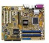
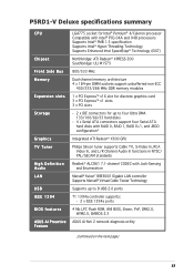
P5RD1-V Deluxe specifications summary CPU Chipset Front Side Bus Memory Expansion slots Storage Graphics TV Tuner High Definition Audio LAN USB IEEE 1394 BIOS features ASUS AI Proactive Feature LGA775 socket for Intel® Pentium® 4/Celeron processor Compatible with Intel® PCG 04A and O4B processors ... Technology (EIST) Northbridge: ATI Radeon® XPRESS 200 Southbridge: ULI M1573 800/533 MHz Dual-channel memory architecture 4 x 184-pin DIMM sockets support unbufferred non-ECC 400/333/266 MHz DDR memory modules 1 x PCI Express™ x16 slot for discrete graphics card 3 x PCI...
P5RD1-V Deluxe specifications summary CPU Chipset Front Side Bus Memory Expansion slots Storage Graphics TV Tuner High Definition Audio LAN USB IEEE 1394 BIOS features ASUS AI Proactive Feature LGA775 socket for Intel® Pentium® 4/Celeron processor Compatible with Intel® PCG 04A and O4B processors ... Technology (EIST) Northbridge: ATI Radeon® XPRESS 200 Southbridge: ULI M1573 800/533 MHz Dual-channel memory architecture 4 x 184-pin DIMM sockets support unbufferred non-ECC 400/333/266 MHz DDR memory modules 1 x PCI Express™ x16 slot for discrete graphics card 3 x PCI...
Motherboard Installation Guide
Page 18
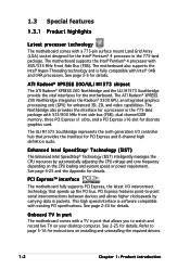
... a TV in the 775-land package. 1.3 Special features 1.3.1 Product highlights Latest processor technology The motherboard comes with a 775-pin surface mount Land Grid Array (LGA) socket designed for details. The motherboard supports the Intel® Pentium® 4 processor with 800/533 MHz Front Side Bus (FSB). See page 2-6 for the Intel...
... a TV in the 775-land package. 1.3 Special features 1.3.1 Product highlights Latest processor technology The motherboard comes with a 775-pin surface mount Land Grid Array (LGA) socket designed for details. The motherboard supports the Intel® Pentium® 4 processor with 800/533 MHz Front Side Bus (FSB). See page 2-6 for the Intel...
Motherboard Installation Guide
Page 25
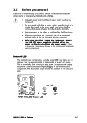
... plugging in soft-off or the p o w e r c o r d i s d e t a c h e d f r o m t h e p o w e r s u p p l y . P5RD1-V ® SB_PWR ON Standby Power P5RD1-V DELUXE Onboard LED OFF Powered Off ASUS P5RD1-V Deluxe 2-1 The illustration below shows the location of the following precautions before you install motherboard components or change any motherboard settings. • Unplug the power cord from the wall socket before touching any component. • Use...
... plugging in soft-off or the p o w e r c o r d i s d e t a c h e d f r o m t h e p o w e r s u p p l y . P5RD1-V ® SB_PWR ON Standby Power P5RD1-V DELUXE Onboard LED OFF Powered Off ASUS P5RD1-V Deluxe 2-1 The illustration below shows the location of the following precautions before you install motherboard components or change any motherboard settings. • Unplug the power cord from the wall socket before touching any component. • Use...
Motherboard Installation Guide
Page 30
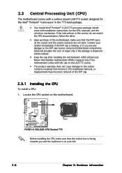
... after installing the motherboard. Locate the CPU socket on the socket and the socket contacts are not bent. ASUS will shoulder the cost of the motherboard, make sure that the PnP cap is on the motherboard. P5RD1-V ® P5RD1-V DELUXE CPU Socket 775 Before installing the CPU, make sure that the socket box is facing towards you and the...
... after installing the motherboard. Locate the CPU socket on the socket and the socket contacts are not bent. ASUS will shoulder the cost of the motherboard, make sure that the PnP cap is on the motherboard. P5RD1-V ® P5RD1-V DELUXE CPU Socket 775 Before installing the CPU, make sure that the socket box is facing towards you and the...

Motherboard Installation Guide
Page 31
...; angle (A), then push the PnP cap from the retention tab. Lift the load lever in the direction of the socket. Gold triangle mark ASUS P5RD1-V Deluxe A 2-7 Retention tab A Load lever PnP cap B This side of the socket box should fit into the CPU notch. Load plate 5. 2. Lift the load plate with your thumb and forefinger...
...; angle (A), then push the PnP cap from the retention tab. Lift the load lever in the direction of the socket. Gold triangle mark ASUS P5RD1-V Deluxe A 2-7 Retention tab A Load lever PnP cap B This side of the socket box should fit into the CPU notch. Load plate 5. 2. Lift the load plate with your thumb and forefinger...
Motherboard Installation Guide
Page 32
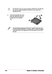
Close the load plate (A), then A push the load lever (B) until it snaps into the socket to the Appendix for more information on the socket and damaging the CPU! 6. Refer to prevent bending the connectors on these CPU features. 2-8 Chapter 2: Hardware information The CPU fits in only one correct orientation. DO NOT force the CPU into the retention tab. B The motherboard supports Intel® Pentium® 4 LGA775 processors with the Enhanced Intel SpeedStep® Technology (EIST) and Hyper-Threading Technology.
Close the load plate (A), then A push the load lever (B) until it snaps into the socket to the Appendix for more information on the socket and damaging the CPU! 6. Refer to prevent bending the connectors on these CPU features. 2-8 Chapter 2: Hardware information The CPU fits in only one correct orientation. DO NOT force the CPU into the retention tab. B The motherboard supports Intel® Pentium® 4 LGA775 processors with the Enhanced Intel SpeedStep® Technology (EIST) and Hyper-Threading Technology.
Motherboard Installation Guide
Page 37
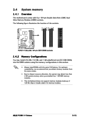
...you installed four 1 GB DDR memory modules. • This motherboard does not support memory modules made up of the sockets: P5RD1-V ® P5RD1-V DELUXE 184-pin DDR DIMM sockets 2.4.2 Memory Configurations You may detect less than 4 GB system memory when you obtain memory modules from the same vendor... this section. • Always install DIMMs with four 184-pin Double Data Rate (DDR) Dual Inline Memory Modules (DIMM) sockets. ASUS P5RD1-V Deluxe 2-13 The following figure illustrates the location of 128 Mb chips or double sided x16 memory modules. DIMM_A1 DIMM_A2 DIMM_B1 DIMM_B2 2.4...
...you installed four 1 GB DDR memory modules. • This motherboard does not support memory modules made up of the sockets: P5RD1-V ® P5RD1-V DELUXE 184-pin DDR DIMM sockets 2.4.2 Memory Configurations You may detect less than 4 GB system memory when you obtain memory modules from the same vendor... this section. • Always install DIMMs with four 184-pin Double Data Rate (DDR) Dual Inline Memory Modules (DIMM) sockets. ASUS P5RD1-V Deluxe 2-13 The following figure illustrates the location of 128 Mb chips or double sided x16 memory modules. DIMM_A1 DIMM_A2 DIMM_B1 DIMM_B2 2.4...
Motherboard Installation Guide
Page 38
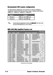
... configuration, the total size of memory module(s) installed per channel must be the same to ensure optimum performance. (DIMM_A1 + DIMM_A2 = DIMM_B1 + DIMM_B2) Channel Channel A Channel B Sockets DIMM_A1 and DIMM_A2 DIMM_B1 and DIMM_B2 In dual-channel configurations, install only i d e n t i c a l (the same type and size) DDR DIMM pairs for each channel. DS - HY5DU56822BT...
... configuration, the total size of memory module(s) installed per channel must be the same to ensure optimum performance. (DIMM_A1 + DIMM_A2 = DIMM_B1 + DIMM_B2) Channel Channel A Channel B Sockets DIMM_A1 and DIMM_A2 DIMM_B1 and DIMM_B2 In dual-channel configurations, install only i d e n t i c a l (the same type and size) DDR DIMM pairs for each channel. DS - HY5DU56822BT...
Motherboard Installation Guide
Page 41
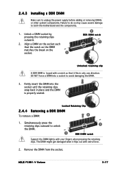
...1 DDR DIMM notch Support the DIMM lightly with a notch so that it flips out with extra force. 2. Remove the DIMM from the socket. Failure to do so may cause severe damage to unplug the power supply before adding or removing DIMMs or other system components. 2.4.3 Installing ...a DDR DIMM Make sure to both the motherboard and the components. 1. Unlock a DIMM socket by pressing the retaining clips outward. 2. The DIMM might get damaged when it fits in place and the DIMM is keyed with your fingers when pressing the retaining clips. ASUS P5RD1-V Deluxe 2-17
...1 DDR DIMM notch Support the DIMM lightly with a notch so that it flips out with extra force. 2. Remove the DIMM from the socket. Failure to do so may cause severe damage to unplug the power supply before adding or removing DIMMs or other system components. 2.4.3 Installing ...a DDR DIMM Make sure to both the motherboard and the components. 1. Unlock a DIMM socket by pressing the retaining clips outward. 2. The DIMM might get damaged when it fits in place and the DIMM is keyed with your fingers when pressing the retaining clips. ASUS P5RD1-V Deluxe 2-17


