User Guide
Page 3
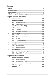
Contents Notices...v Safety information vi About this guide vii P5QL-VM DO specifications summary viii Chapter 1: Product introduction 1.1 Before you proceed 1-1 1.2 Motherboard overview 1-2 1.2.1 Motherboard layout 1-2 1.2.2 Layout contents 1-2 1.3... 1-12 1.8 Software support 1-18 1.8.1 Installing an operating system 1-18 1.8.2 Support DVD information 1-18 Chapter 2: BIOS information 2.1 Managing and updating your BIOS 2-1 2.1.1 ASUS Update utility 2-1 2.1.2 ASUS EZ Flash 2 utility 2-2 2.1.3 ASUS CrashFree BIOS 3 utility 2-3 2.2 BIOS setup program 2-4 2.3 Main menu 2-4 iii
Contents Notices...v Safety information vi About this guide vii P5QL-VM DO specifications summary viii Chapter 1: Product introduction 1.1 Before you proceed 1-1 1.2 Motherboard overview 1-2 1.2.1 Motherboard layout 1-2 1.2.2 Layout contents 1-2 1.3... 1-12 1.8 Software support 1-18 1.8.1 Installing an operating system 1-18 1.8.2 Support DVD information 1-18 Chapter 2: BIOS information 2.1 Managing and updating your BIOS 2-1 2.1.1 ASUS Update utility 2-1 2.1.2 ASUS EZ Flash 2 utility 2-2 2.1.3 ASUS CrashFree BIOS 3 utility 2-3 2.2 BIOS setup program 2-4 2.3 Main menu 2-4 iii
User Guide
Page 7
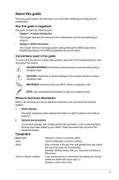
... Your product package may have been added by your dealer. Example: ++ vii Detailed descriptions of the standard package. ASUS websites The ASUS website provides updated information on ASUS hardware and software products. 2. Typography Bold text Italics ++ Indicates a menu or an item to help you must ... NOTE: Tips and additional information to select. These documents are not part of the BIOS parameters are linked with a plus sign (+). Used to change system settings through the BIOS setup menus. If you perform certain tasks properly, take note of the motherboard and ...
... Your product package may have been added by your dealer. Example: ++ vii Detailed descriptions of the standard package. ASUS websites The ASUS website provides updated information on ASUS hardware and software products. 2. Typography Bold text Italics ++ Indicates a menu or an item to help you must ... NOTE: Tips and additional information to select. These documents are not part of the BIOS parameters are linked with a plus sign (+). Used to change system settings through the BIOS setup menus. If you perform certain tasks properly, take note of the motherboard and ...

User Guide
Page 8
...Supports up to 10 USB 2.0/1.1 ports (4 ports at mid-board, 6 ports at the back panel) Intel® 82567LF Gigabit LAN Phy controller ASUS CrashFree BIOS 3 ASUS Q-Fan ASUS EZ Flash 2 ASUS MyLogo 2 1 x PS/2 Keyboard port 1 x PS/2 Mouse port 1 x COM port 1 x RJ45 port 1 x VGA port 1 ...ASUS special features Back panel I /O ports (continued on the next page) viii resolution: 2048 x 1536 x32Bpp @75Hz DVI Max. Hence, a total installed memory of less than 3GB is recommended if you install a total memory of 4GB or more, Windows® 32-bit operating system may only recognize less than 3GB. P5QL-VM...
...Supports up to 10 USB 2.0/1.1 ports (4 ports at mid-board, 6 ports at the back panel) Intel® 82567LF Gigabit LAN Phy controller ASUS CrashFree BIOS 3 ASUS Q-Fan ASUS EZ Flash 2 ASUS MyLogo 2 1 x PS/2 Keyboard port 1 x PS/2 Mouse port 1 x COM port 1 x RJ45 port 1 x VGA port 1 ...ASUS special features Back panel I /O ports (continued on the next page) viii resolution: 2048 x 1536 x32Bpp @75Hz DVI Max. Hence, a total installed memory of less than 3GB is recommended if you install a total memory of 4GB or more, Windows® 32-bit operating system may only recognize less than 3GB. P5QL-VM...

User Guide
Page 9
P5QL-VM DO specifications summary Internal I/O connectors BIOS Accessories Support DVD Form Factor 2 x USB 2.0/1.1 connectors support additional 4 USB 2.0/1.1 ports 6 x SATA connectors 1 x LPT connector 1 x COM connector 1 x Chassis fan connector 1 x CPU fan ... 1 x 24-pin EATX power connector 1 x 4-pin ATX 12V power connector 2 x 16Mb Flash ROM, AMI BIOS, PnP, DMI2.0, WfM2.0, SM BIOS 2.5, ACPI2.0a 2 x Serial ATA cables 1 x I/O shield 1 x Support DVD 1 x User Manual Drivers ASUS Update ASUS PC Probe II Intel® IT Director Anti-Virus software (OEM version) uATX form factor: 9.6 in x 9.0 ...
P5QL-VM DO specifications summary Internal I/O connectors BIOS Accessories Support DVD Form Factor 2 x USB 2.0/1.1 connectors support additional 4 USB 2.0/1.1 ports 6 x SATA connectors 1 x LPT connector 1 x COM connector 1 x Chassis fan connector 1 x CPU fan ... 1 x 24-pin EATX power connector 1 x 4-pin ATX 12V power connector 2 x 16Mb Flash ROM, AMI BIOS, PnP, DMI2.0, WfM2.0, SM BIOS 2.5, ACPI2.0a 2 x Serial ATA cables 1 x I/O shield 1 x Support DVD 1 x User Manual Drivers ASUS Update ASUS PC Probe II Intel® IT Director Anti-Virus software (OEM version) uATX form factor: 9.6 in x 9.0 ...

User Guide
Page 11
... ICS 9LPRS916 PCIEX16 2 PWR_FAN Intel® 82567LF PCI1 Intel® ICH10D Lithium Cell CMOS Power 6 CHASSIS CLRTC SB_PWR PCI2 P5QL-VM DO Super I/O 7 16Mb 16Mb SATA5 SATA3 SATA1 TPM VIA VT1705 CD PCI3 BIOS BIOS SATA6 SATA4 SATA2 8 F_PANEL USBPW7-10 USB910 USB78 COM2 LPT AAFP 17 16 15 14 13 12 11 10...
... ICS 9LPRS916 PCIEX16 2 PWR_FAN Intel® 82567LF PCI1 Intel® ICH10D Lithium Cell CMOS Power 6 CHASSIS CLRTC SB_PWR PCI2 P5QL-VM DO Super I/O 7 16Mb 16Mb SATA5 SATA3 SATA1 TPM VIA VT1705 CD PCI3 BIOS BIOS SATA6 SATA4 SATA2 8 F_PANEL USBPW7-10 USB910 USB78 COM2 LPT AAFP 17 16 15 14 13 12 11 10...

User Guide
Page 13
... Windows® OS. - Heat-Sink Package VD29608A8A-25EG80813 Heat-Sink Package Heat-Sink Package AM4B5708JQJS8E0751C AM4B5808FEWS8E0909C Heat-Sink Package Heat-Sink Package Timing DIMM (BIOS) 4-4-4-12 4-4-4-12 5 5 4 DIMM Support Voltage A* B* C* 2.0~2.1V • • • 1.9~2.1V continued on the next page ... DIMM pair in DIMM_A2 and DIMM_B2 (black slots). • Due to 16GB on W�in Channel A and Channel B. P5Q-VM DO Motherboard Qualified Vendors List (QVL) DDR2-800MHz capability Vendor A-Data A-Data A-Data A-Data Apacer Apacer Corsair Corsair Part No. ...
... Windows® OS. - Heat-Sink Package VD29608A8A-25EG80813 Heat-Sink Package Heat-Sink Package AM4B5708JQJS8E0751C AM4B5808FEWS8E0909C Heat-Sink Package Heat-Sink Package Timing DIMM (BIOS) 4-4-4-12 4-4-4-12 5 5 4 DIMM Support Voltage A* B* C* 2.0~2.1V • • • 1.9~2.1V continued on the next page ... DIMM pair in DIMM_A2 and DIMM_B2 (black slots). • Due to 16GB on W�in Channel A and Channel B. P5Q-VM DO Motherboard Qualified Vendors List (QVL) DDR2-800MHz capability Vendor A-Data A-Data A-Data A-Data Apacer Apacer Corsair Corsair Part No. ...

User Guide
Page 14
... DS Micron 8AG27 D9JWB OCZ2G800R22GK 1024MB DS OCZ Heat-Sink Package OCZ2P800R22GK 1024MB DS OCZ Heat-Sink Package (continued on the next page) Timing DIMM (BIOS) 5 5 5 4-4-4-12 4-4-4-12 4-4-4-12 5-5-5-15 DIMM Support Voltage A* B* C 4 • •• 5 • •• 4 • •• 5 •• 5 • ••... 5 1.8V 6 1.8V • 5-5-5-15 2.0V • 5 1.8V • 6 1.8V • 6 1.8V • 6-6-6-12 • 6-6-6-12 • 4-5-5-15 2.0V • 4-4-4-15 1.9 • - 2.1 V ASUS P5QL-VM DO 1-5
... DS Micron 8AG27 D9JWB OCZ2G800R22GK 1024MB DS OCZ Heat-Sink Package OCZ2P800R22GK 1024MB DS OCZ Heat-Sink Package (continued on the next page) Timing DIMM (BIOS) 5 5 5 4-4-4-12 4-4-4-12 4-4-4-12 5-5-5-15 DIMM Support Voltage A* B* C 4 • •• 5 • •• 4 • •• 5 •• 5 • ••... 5 1.8V 6 1.8V • 5-5-5-15 2.0V • 5 1.8V • 6 1.8V • 6 1.8V • 6-6-6-12 • 6-6-6-12 • 4-5-5-15 2.0V • 4-4-4-15 1.9 • - 2.1 V ASUS P5QL-VM DO 1-5

User Guide
Page 16
... DS Elpida E5108AJBG-6E-E DS Transced TQ243PCF8T0834 SS PSC A3R12E3GEF633ACAOY Timing DIMM (BIOS) 5 5 5 5 5 5 5 5 5 5 5 5 5 5 5 DIMM Support Voltage A* B* C 1.8V 1.8V 1.8V 1.8V • • • SS - Double - ASUS P5QL-VM DO 1-7 Size GEIL GX22GB5300LX 2048MB GEIL GX24GB5300LDC 2048MB Kingmax KLCC28F-A8KB5 512MB Kingmax...1G 1024MB Transcend JM667QLU-2G 2048MB Twinmos 8D-A3JK5MPETP 512MB SS/ Chip DS Brand Chip No. Visit the ASUS website at www.asus.com for the latest QVL. DDR2-667MHz capability Vendor Part No. sided DIMM support: • A*: Supports...
... DS Elpida E5108AJBG-6E-E DS Transced TQ243PCF8T0834 SS PSC A3R12E3GEF633ACAOY Timing DIMM (BIOS) 5 5 5 5 5 5 5 5 5 5 5 5 5 5 5 DIMM Support Voltage A* B* C 1.8V 1.8V 1.8V 1.8V • • • SS - Double - ASUS P5QL-VM DO 1-7 Size GEIL GX22GB5300LX 2048MB GEIL GX24GB5300LDC 2048MB Kingmax KLCC28F-A8KB5 512MB Kingmax...1G 1024MB Transcend JM667QLU-2G 2048MB Twinmos 8D-A3JK5MPETP 512MB SS/ Chip DS Brand Chip No. Visit the ASUS website at www.asus.com for the latest QVL. DDR2-667MHz capability Vendor Part No. sided DIMM support: • A*: Supports...

User Guide
Page 17
...; Install the software drivers for the card. 2. Align the card connector with the screw. 6. When using PCI cards on the system and change the necessary BIOS settings, if any. Assign an IRQ to the chassis with the slot and press firmly until the card is already installed in a chassis). 3. The following... the card. 3. 1.5 Expansion slots In the future, you may cause you intend to use. 4. Remove the chassis cover (if your motherboard is completely seated on BIOS setup. 2.
...; Install the software drivers for the card. 2. Align the card connector with the screw. 6. When using PCI cards on the system and change the necessary BIOS settings, if any. Assign an IRQ to the chassis with the slot and press firmly until the card is already installed in a chassis). 3. The following... the card. 3. 1.5 Expansion slots In the future, you may cause you intend to use. 4. Remove the chassis cover (if your motherboard is completely seated on BIOS setup. 2.

User Guide
Page 18
...+5VSB lead, and a corresponding setting in CMOS, which include system setup information such as system passwords. CLRTC 12 23 P5QL-VM DO Normal Clear RTC (Default) P5QL-VM DO Clear RTC RAM To erase the RTC RAM: 1. Turn OFF the computer and unplug the power cord. 2. Move... cut off the AC power, then reboot the system, the BIOS automatically resets parameter settings to pins 2-3 (+5VSB), you set this jumper to default values. 2. KBPWR 12 23 +5V +5VSB (Default) P5QL-VM DO P5QL-VM DO Keyboard Power Setting ASUS P5QL-VM DO 1-9 Removing the cap will cause system boot failure! ...
...+5VSB lead, and a corresponding setting in CMOS, which include system setup information such as system passwords. CLRTC 12 23 P5QL-VM DO Normal Clear RTC (Default) P5QL-VM DO Clear RTC RAM To erase the RTC RAM: 1. Turn OFF the computer and unplug the power cord. 2. Move... cut off the AC power, then reboot the system, the BIOS automatically resets parameter settings to pins 2-3 (+5VSB), you set this jumper to default values. 2. KBPWR 12 23 +5V +5VSB (Default) P5QL-VM DO P5QL-VM DO Keyboard Power Setting ASUS P5QL-VM DO 1-9 Removing the cap will cause system boot failure! ...

User Guide
Page 20
... connects to the tape, CD, DVD player, or other serial devices. 12. USB 2.0 ports 1 and 2. PS/2 Keyboard port. Disable Intel® ME function before updating BIOS. 8. ASUS P5QL-VM DO 1-11
... connects to the tape, CD, DVD player, or other serial devices. 12. USB 2.0 ports 1 and 2. PS/2 Keyboard port. Disable Intel® ME function before updating BIOS. 8. ASUS P5QL-VM DO 1-11
User Guide
Page 24
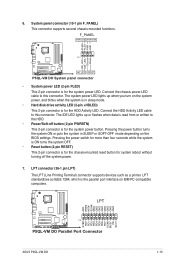
... without turning off button (2-pin PWRBTN) This 2-pin connector is for the HDD Activity LED. Ground Reset P5QL-VM DO HD_LED RESET P5QL-VM DO System panel connector • System power LED (2-pin PLED) This 2-pin connector is for the system...GND GND GND GND STB# PD0 PD1 PD2 PD3 PD4 PD5 PD6 PD7 ACK# BUSY PE SLCT P5QL-VM DO PIN 1 P5QL-VM DO Parallel Port Connector ASUS P5QL-VM DO 1-15 F_PANEL PWR LED PWR BTN PLED+ PLEDPWR GND PIN 1 IDE_LED+ IDE_LED- The ... lights up or flashes when data is the parallel port interface on the BIOS settings. LPT standardizes as a printer.
... without turning off button (2-pin PWRBTN) This 2-pin connector is for the HDD Activity LED. Ground Reset P5QL-VM DO HD_LED RESET P5QL-VM DO System panel connector • System power LED (2-pin PLED) This 2-pin connector is for the system...GND GND GND GND STB# PD0 PD1 PD2 PD3 PD4 PD5 PD6 PD7 ACK# BUSY PE SLCT P5QL-VM DO PIN 1 P5QL-VM DO Parallel Port Connector ASUS P5QL-VM DO 1-15 F_PANEL PWR LED PWR BTN PLED+ PLEDPWR GND PIN 1 IDE_LED+ IDE_LED- The ... lights up or flashes when data is the parallel port interface on the BIOS settings. LPT standardizes as a printer.

User Guide
Page 25
... connector is then generated as a chassis intrusion event. The signal is for a chassis-mounted intrusion detection sensor or switch. CHASSIS GND Chassis Signal P5QL-VM DO +5VSB_MB P5QL-VM DO Chassis intrusion connector 1-16 Chapter 1: Product introduction GND PRESENCE# SENSE1_RETUR SENSE2_RETUR AGND NC NC NC AAFP PIN 1 PIN 1 MIC2 MICPWR Line out_R...Audio or AC`97 audio standard. Connect one end of the front panel audio I /O module that the Front Panel Type item in the BIOS is removed or replaced. The chassis intrusion sensor or switch sends a high-level signal to [AC97].
... connector is then generated as a chassis intrusion event. The signal is for a chassis-mounted intrusion detection sensor or switch. CHASSIS GND Chassis Signal P5QL-VM DO +5VSB_MB P5QL-VM DO Chassis intrusion connector 1-16 Chapter 1: Product introduction GND PRESENCE# SENSE1_RETUR SENSE2_RETUR AGND NC NC NC AAFP PIN 1 PIN 1 MIC2 MICPWR Line out_R...Audio or AC`97 audio standard. Connect one end of the front panel audio I /O module that the Front Panel Type item in the BIOS is removed or replaced. The chassis intrusion sensor or switch sends a high-level signal to [AC97].

User Guide
Page 28
...DVD into the optical drive. Copy the original motherboard BIOS using this utility. Always update the utility to get all Windows® applications before you update the BIOS using the ASUS Update utility. 2.1.1 ASUS Update utility The ASUS Update is a utility that allows you to manage..., save, and update the motherboard BIOS in Windows® environment. • ASUS Update requires an Internet connection either of ...
...DVD into the optical drive. Copy the original motherboard BIOS using this utility. Always update the utility to get all Windows® applications before you update the BIOS using the ASUS Update utility. 2.1.1 ASUS Update utility The ASUS Update is a utility that allows you to manage..., save, and update the motherboard BIOS in Windows® environment. • ASUS Update requires an Internet connection either of ...
User Guide
Page 29
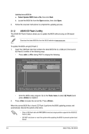
.... 3. Go to the Tools menu to select EZ Flash 2 and press to prevent system boot failure! 2-2 ASUS P5QL-VM DO/SI When the correct BIOS file is found, EZ Flash 2 performs the BIOS updating process and automatically reboots the system when done. • Only a USB flash disk with FAT 32/16...2. Follow the onscreen instructions to complete the updating process. 2.1.2 ASUS EZ Flash 2 utility The ASUS EZ Flash 2 feature allows you to display the following: ASUSTek EZ Flash 2 BIOS ROM Utility V3.38 FLASH TYPE: MXIC 25L1605A Current ROM BOARD: P5Q-VM DO VER: 0211 (H:00 B:06) DATE: 06/02/2009 ...
.... 3. Go to the Tools menu to select EZ Flash 2 and press to prevent system boot failure! 2-2 ASUS P5QL-VM DO/SI When the correct BIOS file is found, EZ Flash 2 performs the BIOS updating process and automatically reboots the system when done. • Only a USB flash disk with FAT 32/16...2. Follow the onscreen instructions to complete the updating process. 2.1.2 ASUS EZ Flash 2 utility The ASUS EZ Flash 2 feature allows you to display the following: ASUSTek EZ Flash 2 BIOS ROM Utility V3.38 FLASH TYPE: MXIC 25L1605A Current ROM BOARD: P5Q-VM DO VER: 0211 (H:00 B:06) DATE: 06/02/2009 ...

User Guide
Page 30
...-ROM... Bad BIOS checksum. Checking for the BIOS file. Reading file "P5QLVMDO.ROM". Start Erasing... Download the latest BIOS file from the ASUS website at www.asus.com. otherwise, the utility will not function. • If your system. Starting BIOS recovery... 2.1.3 ASUS CrashFree BIOS 3 utility The ASUS CrashFree BIOS 3 is connected... the updating process. • Only a USB flash disk with FAT 32/16 format and single partition supports ASUS CrashFree BIOS 3. The recovered BIOS may not be smaller than 8GB. • DO NOT shut down or reset the system while updating the...
...-ROM... Bad BIOS checksum. Checking for the BIOS file. Reading file "P5QLVMDO.ROM". Start Erasing... Download the latest BIOS file from the ASUS website at www.asus.com. otherwise, the utility will not function. • If your system. Starting BIOS recovery... 2.1.3 ASUS CrashFree BIOS 3 utility The ASUS CrashFree BIOS 3 is connected... the updating process. • Only a USB flash disk with FAT 32/16 format and single partition supports ASUS CrashFree BIOS 3. The recovered BIOS may not be smaller than 8GB. • DO NOT shut down or reset the system while updating the...

User Guide
Page 31
... Date [Day xx/xx/xxxx] Allows you to select a field. Select the Load Setup Defaults item under the Exit menu. Main AI Tweaker BIOS SETUP UTILITY Advanced Power Boot Tools Exit System Time [18:43:30] System Date [Fri 05/01/2009] SATA1 SATA2 SATA3 SATA4 SATA5 SATA6 ... Detected] :[Not Detected] :[Not Detected] :[Not Detected] :[Not Detected] :[Not Detected] Use [ENTER], [TAB] or [SHIFT-TAB] to set the system date. 2-4 ASUS P5QL-VM DO/SI This section explains how to configure your system, or prompted to turn the system off then back on your data or system. They...
... Date [Day xx/xx/xxxx] Allows you to select a field. Select the Load Setup Defaults item under the Exit menu. Main AI Tweaker BIOS SETUP UTILITY Advanced Power Boot Tools Exit System Time [18:43:30] System Date [Fri 05/01/2009] SATA1 SATA2 SATA3 SATA4 SATA5 SATA6 ... Detected] :[Not Detected] :[Not Detected] :[Not Detected] :[Not Detected] :[Not Detected] Use [ENTER], [TAB] or [SHIFT-TAB] to set the system date. 2-4 ASUS P5QL-VM DO/SI This section explains how to configure your system, or prompted to turn the system off then back on your data or system. They...

User Guide
Page 32
...Storage Configuration The Storage Configuration menu allows you to configure your device is installed in the system. Chapter 2: BIOS information 2-5 2.3.3 SATA 1-6 While entering Setup, the BIOS automatically detects the presence of IDE drive. These items show Not Detected if no SATA device is either a... PIO Mode [Auto] Selects the PIO mode. Configuration options: [Auto] [0] [1] [2] [3] [4] DMA Mode [Auto] Selects the DMA mode. The BIOS automatically detects the values opposite the dimmed items (Device, Vendor, Size, LBA Mode, Block Mode, PIO Mode, Async DMA, Ultra DMA, and SMART...
...Storage Configuration The Storage Configuration menu allows you to configure your device is installed in the system. Chapter 2: BIOS information 2-5 2.3.3 SATA 1-6 While entering Setup, the BIOS automatically detects the presence of IDE drive. These items show Not Detected if no SATA device is either a... PIO Mode [Auto] Selects the PIO mode. Configuration options: [Auto] [0] [1] [2] [3] [4] DMA Mode [Auto] Selects the DMA mode. The BIOS automatically detects the values opposite the dimmed items (Device, Vendor, Size, LBA Mode, Block Mode, PIO Mode, Async DMA, Ultra DMA, and SMART...

User Guide
Page 33
... The Ai Tweaker menu items allow you to achieve desired CPU internal frequency. The BIOS automatically detects the items in this menu. BIOS SETUP UTILITY Main AI Tweaker Advanced Power Boot Tools Configure System Performance Settings Ai Overclock.... Allows you an overview of the preset overclocking configuration options: Manual - Loads the overclock profile. 2-6 ASUS P5QL-VM DO/SI This will be effective only if device is accessed throuh BIOS. Select either one of the general system specifications. Auto - Overclock Profile - Configuration options: [0] [5] ...
... The Ai Tweaker menu items allow you to achieve desired CPU internal frequency. The BIOS automatically detects the items in this menu. BIOS SETUP UTILITY Main AI Tweaker Advanced Power Boot Tools Configure System Performance Settings Ai Overclock.... Allows you an overview of the preset overclocking configuration options: Manual - Loads the overclock profile. 2-6 ASUS P5QL-VM DO/SI This will be effective only if device is accessed throuh BIOS. Select either one of the general system specifications. Auto - Overclock Profile - Configuration options: [0] [5] ...

User Guide
Page 34
..., and setting a low VCore voltage may cause the system to the system bus and PCI bus. Chapter 2: BIOS information 2-7 Refer to set the DDR2 operating frequency. If this item is auto-detected by the BIOS. Configuration options: [Auto] [+50mv] [+100mv] [+150mv]. The values range from 1.87V to the default setting. Press +/- The...
..., and setting a low VCore voltage may cause the system to the system bus and PCI bus. Chapter 2: BIOS information 2-7 Refer to set the DDR2 operating frequency. If this item is auto-detected by the BIOS. Configuration options: [Auto] [+50mv] [+100mv] [+150mv]. The values range from 1.87V to the default setting. Press +/- The...


