
User Manual
Page 31
ok A:\> 當 BIOS DOS 31 done Write to file...... BIOS 2.1 使用 AFUDOS BIOS AFUDOS DOS BIOS BIOS 程式。AFUDOS BIOS BIOS BIOS 程式 BIOS 程式。 1.2MB BIOS 1 AFUDOS 程式(afudos. All rights reserved. Reading flash ..... Version 1.19(ASUS V2.07(03.11.24BB)) Copyright (C) 2002 American Megatrends, Inc. exe 2 DOS afudos /o[filename filename A:\>afudos /oOLDBIOS1.rom 3. 按下 afudos /oOLDBIOS1.rom AMI Firmware Update Utility -
ok A:\> 當 BIOS DOS 31 done Write to file...... BIOS 2.1 使用 AFUDOS BIOS AFUDOS DOS BIOS BIOS 程式。AFUDOS BIOS BIOS BIOS 程式 BIOS 程式。 1.2MB BIOS 1 AFUDOS 程式(afudos. All rights reserved. Reading flash ..... Version 1.19(ASUS V2.07(03.11.24BB)) Copyright (C) 2002 American Megatrends, Inc. exe 2 DOS afudos /o[filename filename A:\>afudos /oOLDBIOS1.rom 3. 按下 afudos /oOLDBIOS1.rom AMI Firmware Update Utility -

User Manual
Page 32
... ...... done Reading flash ...... Erasing flash ...... All rights reserved. 更新 BIOS 程式 AFUDOS BIOS 程式。 1 tw.asus.com BIOS 片中。 BIOS BIOS 2. 將 AFUDOS.EXE BIOS 3 DOS afudos /i[filename filename BIOS 程式。 A:\>afudos /iP5B-VM DO.ROM 4. done BIOS 5. 當 BIOS DOS A:\>afudos /iP5B-VM DO.ROM AMI Firmware Update Utility - All rights reserved. done...
... ...... done Reading flash ...... Erasing flash ...... All rights reserved. 更新 BIOS 程式 AFUDOS BIOS 程式。 1 tw.asus.com BIOS 片中。 BIOS BIOS 2. 將 AFUDOS.EXE BIOS 3 DOS afudos /i[filename filename BIOS 程式。 A:\>afudos /iP5B-VM DO.ROM 4. done BIOS 5. 當 BIOS DOS A:\>afudos /iP5B-VM DO.ROM AMI Firmware Update Utility - All rights reserved. done...

User Manual
Page 33
... Message: Do You Want To Save Bios (Y/N) 33 2.2 使用 AwardBIOS Flash BIOS AwardBIOS Flash AwardBIOS Flash 程式(AWDFLASH.EXE BIOS AwardBIOS Flash BIOS 程式。 1 http://tw.asus.com BIOS M2N-VM HDMI.bin FAT 32/16 格式的 USB BIOS 2 CD/DVD AwardBIOS Flash BIOS 3 DOS 4. 當 A BIOS 檔案與 AwardBIOS Flash 5 A awdflash...
... Message: Do You Want To Save Bios (Y/N) 33 2.2 使用 AwardBIOS Flash BIOS AwardBIOS Flash AwardBIOS Flash 程式(AWDFLASH.EXE BIOS AwardBIOS Flash BIOS 程式。 1 http://tw.asus.com BIOS M2N-VM HDMI.bin FAT 32/16 格式的 USB BIOS 2 CD/DVD AwardBIOS Flash BIOS 3 DOS 4. 當 A BIOS 檔案與 AwardBIOS Flash 5 A awdflash...

User Manual
Page 34
... Complete Press to Program: M2A-VM HDMI.bin Programming Flash Memory - OFE00 OK Write OK No Update Write Fail Warning: Don't Turn Off Power Or Reset System! 在更新 BIOS 9 Flash Complete BIOS F1 AwardBIOS Flash Utility for ASUS V1.14 (C) Phoenix Technologies Ltd. 7 BIOS N BIOS 8 BIOS BIOS AwardBIOS Flash Utility for ASUS V1.14 (C) Phoenix Technologies Ltd...
... Complete Press to Program: M2A-VM HDMI.bin Programming Flash Memory - OFE00 OK Write OK No Update Write Fail Warning: Don't Turn Off Power Or Reset System! 在更新 BIOS 9 Flash Complete BIOS F1 AwardBIOS Flash Utility for ASUS V1.14 (C) Phoenix Technologies Ltd. 7 BIOS N BIOS 8 BIOS BIOS AwardBIOS Flash Utility for ASUS V1.14 (C) Phoenix Technologies Ltd...

User Manual
Page 4
... the OS shut down function 1-44 1.12.2 Using the dual function power switch 1-44 Chapter 2: BIOS setup 2.1 Managing and updating your BIOS 2-2 2.1.1 ASUS Update utility 2-2 2.1.2 Creating a bootable floppy disk 2-5 2.1.3 ASUS EZ Flash 2 utility 2-6 2.1.4 AFUDOS utility 2-7 2.1.5 ASUS CrashFree BIOS 3 utility 2-9 2.2 BIOS setup program 2-10 2.2.1 BIOS menu screen 2-11 2.2.2 Menu bar 2-11 2.2.3 Navigation keys 2-11 2.2.4 Menu items 2-12 2.2.5 Sub-menu...
... the OS shut down function 1-44 1.12.2 Using the dual function power switch 1-44 Chapter 2: BIOS setup 2.1 Managing and updating your BIOS 2-2 2.1.1 ASUS Update utility 2-2 2.1.2 Creating a bootable floppy disk 2-5 2.1.3 ASUS EZ Flash 2 utility 2-6 2.1.4 AFUDOS utility 2-7 2.1.5 ASUS CrashFree BIOS 3 utility 2-9 2.2 BIOS setup program 2-10 2.2.1 BIOS menu screen 2-11 2.2.2 Menu bar 2-11 2.2.3 Navigation keys 2-11 2.2.4 Menu items 2-12 2.2.5 Sub-menu...

User Manual
Page 8
... procedures that you need when installing and configuring the motherboard. It includes description of the jumpers and connectors on ASUS hardware and software products. Refer to change system settings through the BIOS Setup menus. Optional documentation Your product package may have... the motherboard and the new technology it supports. Detailed descriptions of the BIOS parameters are not part of the standard package. ASUS websites The ASUS website provides updated information on the motherboard. • Chapter 2: BIOS setup This chapter tells how to the ASUS contact information...
... procedures that you need when installing and configuring the motherboard. It includes description of the jumpers and connectors on ASUS hardware and software products. Refer to change system settings through the BIOS Setup menus. Optional documentation Your product package may have... the motherboard and the new technology it supports. Detailed descriptions of the BIOS parameters are not part of the standard package. ASUS websites The ASUS website provides updated information on the motherboard. • Chapter 2: BIOS setup This chapter tells how to the ASUS contact information...

User Manual
Page 11
... ASUS Express Gate ASUS Quiet Thermal Solution: - ASUS Noise Filtering ASUS EZ DIY: - ASUS CrashFree BIOS 3 - vChipset (N.B.): 30-step chipset voltage control - PCI Express frequency tuning from 200MHz up to 800MHz at 1MHz increment - ASUS EZ Flash 2 ASUS ...ASUS C.P.R.(CPU Parameter Recall) 1 x PS/2 Keyboard/Mouse combo port 1 x D-Sub port 1 x DVI port 1 x LAN (RJ-45) port 6 x USB 2.0/1.1 ports 8-channel audio ports (continued on the next page) xi Profile - vDIMM: 45-step DRAM voltage control - P5Q-VM specifications summary ASUS Unique features Other features ASUS...
... ASUS Express Gate ASUS Quiet Thermal Solution: - ASUS Noise Filtering ASUS EZ DIY: - ASUS CrashFree BIOS 3 - vChipset (N.B.): 30-step chipset voltage control - PCI Express frequency tuning from 200MHz up to 800MHz at 1MHz increment - ASUS EZ Flash 2 ASUS ...ASUS C.P.R.(CPU Parameter Recall) 1 x PS/2 Keyboard/Mouse combo port 1 x D-Sub port 1 x DVI port 1 x LAN (RJ-45) port 6 x USB 2.0/1.1 ports 8-channel audio ports (continued on the next page) xi Profile - vDIMM: 45-step DRAM voltage control - P5Q-VM specifications summary ASUS Unique features Other features ASUS...
User Manual
Page 12
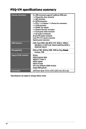
P5Q-VM specifications summary Internal connectors BIOS features Manageability Support DVD contents Form factor 3 x USB connectors support 6 additional USB ports 1 x Floppy disk drive connector 1 x IDE connector 6 x SATA connectors 1 x CPU / 1 x Chassis / 1 x Power fan connectors 1 x COM connector 1 x S/PDIF Out header 1 x Chassis intrusion connector 1 x Front panel audio connector 1 x CD audio in connector 24-pin ATX... power connector 4-pin ATX 12 V power connector System panel connector 8 Mb Flash ROM, AMI BIOS, PnP, DMI2.0, WfM2.0, SM BIOS 2.4, ACPI 2.0a, ASUS CrashFree BIOS 3, ASUS ...
P5Q-VM specifications summary Internal connectors BIOS features Manageability Support DVD contents Form factor 3 x USB connectors support 6 additional USB ports 1 x Floppy disk drive connector 1 x IDE connector 6 x SATA connectors 1 x CPU / 1 x Chassis / 1 x Power fan connectors 1 x COM connector 1 x S/PDIF Out header 1 x Chassis intrusion connector 1 x Front panel audio connector 1 x CD audio in connector 24-pin ATX... power connector 4-pin ATX 12 V power connector System panel connector 8 Mb Flash ROM, AMI BIOS, PnP, DMI2.0, WfM2.0, SM BIOS 2.4, ACPI 2.0a, ASUS CrashFree BIOS 3, ASUS ...

User Manual
Page 18
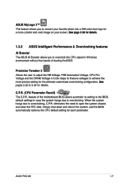
...65533;2�-�3�9��f�o�r�d��e�t�a�il�s�. ASUS CrashFree BIOS 3 ASUS CrashFree BIOS 3 allows users to conveniently store or load multiple BIOS settings. ASUS EZ Flash 2 EZ Flash 2 is caused by different climate conditions in the CMOS or a separate... repetitive and stationary noises (non-voice signals) like Skype, online game, video conference and recording. Profile The motherboard features the ASUS O.C. ASUS O.C. See page 2-9 for details. 1-6 Chapter 1: Product Introduction
...65533;2�-�3�9��f�o�r�d��e�t�a�il�s�. ASUS CrashFree BIOS 3 ASUS CrashFree BIOS 3 allows users to conveniently store or load multiple BIOS settings. ASUS EZ Flash 2 EZ Flash 2 is caused by different climate conditions in the CMOS or a separate... repetitive and stationary noises (non-voice signals) like Skype, online game, video conference and recording. Profile The motherboard features the ASUS O.C. ASUS O.C. See page 2-9 for details. 1-6 Chapter 1: Product Introduction
User Manual
Page 19
...and clear the RTC data. C.P.R. (CPU Parameter Recall) The C.P.R. eliminates the need to overclocking, C.P.R. ASUS P5Q-VM 1-7 Simply shut down and reboot the system, and the BIOS automatically restores the CPU default setting for details. Precision Tweaker 2 Allows the user to adjust the NB ...;�il�s�. 1.3.3 ASUS Intelligent Performance & Overclocking features AI Booster The ASUS AI Booster allows you to overclock the CPU speed in Windows environment without the hassle of the motherboard BIOS allows automatic re-setting to the BIOS default settings in 0.02v steps...
...and clear the RTC data. C.P.R. (CPU Parameter Recall) The C.P.R. eliminates the need to overclocking, C.P.R. ASUS P5Q-VM 1-7 Simply shut down and reboot the system, and the BIOS automatically restores the CPU default setting for details. Precision Tweaker 2 Allows the user to adjust the NB ...;�il�s�. 1.3.3 ASUS Intelligent Performance & Overclocking features AI Booster The ASUS AI Booster allows you to overclock the CPU speed in Windows environment without the hassle of the motherboard BIOS allows automatic re-setting to the BIOS default settings in 0.02v steps...

User Manual
Page 32
.... 64-bit Windows® XP Professional x64 Edition Windows® Vista x64 Edition • The default memory operation frequency is recommended. • This motherboard does not support memory modules made up to 16 GB on its SPD. You may install a maximum of 256 Mb chips. • Due to ...chipset limitation, this motherboard can manually adjust DRAM Frequency in BIOS settings. The system maps the total size of less than 3 GB is dependent on the operating systems listed below. Under the default...
.... 64-bit Windows® XP Professional x64 Edition Windows® Vista x64 Edition • The default memory operation frequency is recommended. • This motherboard does not support memory modules made up to 16 GB on its SPD. You may install a maximum of 256 Mb chips. • Due to ...chipset limitation, this motherboard can manually adjust DRAM Frequency in BIOS settings. The system maps the total size of less than 3 GB is dependent on the operating systems listed below. Under the default...
User Manual
Page 37
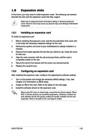
...Failure to do not need to install expansion cards. Remove the system unit cover (if your motherboard is completely seated on the next page for details. Align the card connector with the slot ... and the card inoperable. Keep the screw for the card. 2. Refer to use . 4. ASUS P5Q-VM 1-25 The following sub‑sections describe the slots and the expansion cards that came with the... screw you intend to the table on the slot. 5. Secure the card to the tables on BIOS setup. 2. Refer to the chassis with it by adjusting the software settings. 1. See Chapter ...
...Failure to do not need to install expansion cards. Remove the system unit cover (if your motherboard is completely seated on the next page for details. Align the card connector with the slot ... and the card inoperable. Keep the screw for the card. 2. Refer to use . 4. ASUS P5Q-VM 1-25 The following sub‑sections describe the slots and the expansion cards that came with the... screw you intend to the table on the slot. 5. Secure the card to the tables on BIOS setup. 2. Refer to the chassis with it by adjusting the software settings. 1. See Chapter ...

User Manual
Page 40
...-enter data. To erase the RTC RAM 1. function. Turn OFF the computer and unplug the power cord. 2. Hold down and reboot the system so the BIOS can clear the CMOS memory of date, time, and system setup parameters by erasing the CMOS RTC RAM data. Shut down the key during the... boot process and enter BIOS setup to enable C.P.R. For system failure due to clear the Real Time Clock (RTC) RAM in CMOS, which include system setup information such as system...
...-enter data. To erase the RTC RAM 1. function. Turn OFF the computer and unplug the power cord. 2. Hold down and reboot the system so the BIOS can clear the CMOS memory of date, time, and system setup parameters by erasing the CMOS RTC RAM data. Shut down the key during the... boot process and enter BIOS setup to enable C.P.R. For system failure due to clear the Real Time Clock (RTC) RAM in CMOS, which include system setup information such as system...
User Manual
Page 41
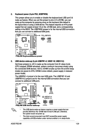
...you can provide 500mA on the +5VSB lead, and a corresponding setting in reduced power mode). This feature requires an ATX power supply that can supply at least 1A on the +5VSB lead for the internal USB connectors that can wake up ...disable the keyboard and USB port 5-6 wake-up from S1 sleep mode (CPU stopped, DRAM refreshed, system running in sleep mode. ASUS P5Q-VM 1-29 2. The USBPW1-4 jumper is for each USB port; When you set this jumper to pins 2-3 (+5VSB), you to ... supply that you can connect to CPU, DRAM in slow refresh, power supply in the BIOS. USB7-10;
...you can provide 500mA on the +5VSB lead, and a corresponding setting in reduced power mode). This feature requires an ATX power supply that can supply at least 1A on the +5VSB lead for the internal USB connectors that can wake up ...disable the keyboard and USB port 5-6 wake-up from S1 sleep mode (CPU stopped, DRAM refreshed, system running in sleep mode. ASUS P5Q-VM 1-29 2. The USBPW1-4 jumper is for each USB port; When you set this jumper to pins 2-3 (+5VSB), you to ... supply that you can connect to CPU, DRAM in slow refresh, power supply in the BIOS. USB7-10;
User Manual
Page 52
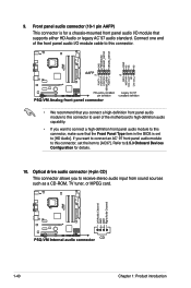
...]. If you want to connect an AC' 97 front panel audio module to this connector, make sure that the Front Panel Type item in the BIOS is for details. 10. Refer to 2.5.3 Onboard Devices Configuration for a chassis-mounted front panel audio I /O module cable to [HD Audio]. Front ... one end of the front panel audio I /O module that you connect a high-definition front panel audio module to this connector to avail of the motherboard's high-definition audio capability. • If you want to connect a high-definition front panel audio module to this connector, set to this connector. ...
...]. If you want to connect an AC' 97 front panel audio module to this connector, make sure that the Front Panel Type item in the BIOS is for details. 10. Refer to 2.5.3 Onboard Devices Configuration for a chassis-mounted front panel audio I /O module cable to [HD Audio]. Front ... one end of the front panel audio I /O module that you connect a high-definition front panel audio module to this connector to avail of the motherboard's high-definition audio capability. • If you want to connect a high-definition front panel audio module to this connector, set to this connector. ...

User Manual
Page 54
...connector is for system reboot without turning off the system power. 1-42 Chapter 1: Product introduction Pressing the power button turns the system on the BIOS settings. 12. The IDE LED lights up when you to this connector. Pressing the power switch for more than four seconds while the system is... flashes when data is read from or written to this connector. Connect the chassis power LED cable to hear system beeps and warnings. • ATX power button/soft-off mode depending on or puts the system in sleep mode. • Hard disk drive activity LED (2-pin IDE_LED) This 2-...
...connector is for system reboot without turning off the system power. 1-42 Chapter 1: Product introduction Pressing the power button turns the system on the BIOS settings. 12. The IDE LED lights up when you to this connector. Pressing the power switch for more than four seconds while the system is... flashes when data is read from or written to this connector. Connect the chassis power LED cable to hear system beeps and warnings. • ATX power button/soft-off mode depending on or puts the system in sleep mode. • Hard disk drive activity LED (2-pin IDE_LED) This 2-...

User Manual
Page 55
...chain) c. 1.11 Starting up for assistance. External SCSI devices (starting with ATX power supplies, the system LED lights up when you do not see BIOS beep codes table below) or additional messages appear on . BIOS Beep One short beep One continuous beep followed by two short beeps then ... power connector at the back of the system chassis. 4. ASUS P5Q-VM 1-43 Connect the power cord to disabled No keyboard detected No memory detected No VGA detected Hardware component failure 7. Monitor b. System power 6. If you press the ATX power button. Be sure that is equipped with "green"...
...chain) c. 1.11 Starting up for assistance. External SCSI devices (starting with ATX power supplies, the system LED lights up when you do not see BIOS beep codes table below) or additional messages appear on . BIOS Beep One short beep One continuous beep followed by two short beeps then ... power connector at the back of the system chassis. 4. ASUS P5Q-VM 1-43 Connect the power cord to disabled No keyboard detected No memory detected No VGA detected Hardware component failure 7. Monitor b. System power 6. If you press the ATX power button. Be sure that is equipped with "green"...

User Manual
Page 56
... after Windows® shuts down. Pressing the power switch for less than four seconds lets the system enter the soft-off mode regardless of the BIOS setting. Refer to shut down the computer. 3. If you are using Windows® Vista: 1. Click the Start button and then select Turn Off Computer. 2. Click... is ON, pressing the power switch for more than four seconds puts the system to sleep mode or to soft-off mode, depending on the BIOS setting. 1.12 Turning off the computer 1.12.1 Using the OS shut down function If you are using Windows® XP: 1.
... after Windows® shuts down. Pressing the power switch for less than four seconds lets the system enter the soft-off mode regardless of the BIOS setting. Refer to shut down the computer. 3. If you are using Windows® Vista: 1. Click the Start button and then select Turn Off Computer. 2. Click... is ON, pressing the power switch for more than four seconds puts the system to sleep mode or to soft-off mode, depending on the BIOS setting. 1.12 Turning off the computer 1.12.1 Using the OS shut down function If you are using Windows® XP: 1.
User Manual
Page 57
Detailed descriptions of the BIOS parameters are also provided. This chapter tells how to change the Chapter 2: BIOS se2tup system settings through the BIOS Setup menus.
Detailed descriptions of the BIOS parameters are also provided. This chapter tells how to change the Chapter 2: BIOS se2tup system settings through the BIOS Setup menus.

User Manual
Page 58
... fails or gets corrupted.) Refer to manage, save, and update the motherboard BIOS in the support DVD that comes with the motherboard package. ASUS AFUDOS (Updates the BIOS using the ASUS Update or AFUDOS utilities. 2.1.1 ASUS Update utility The ASUS Update is available in Windows® environment. The ASUS Update utility allows you need to : • Save the current...
... fails or gets corrupted.) Refer to manage, save, and update the motherboard BIOS in the support DVD that comes with the motherboard package. ASUS AFUDOS (Updates the BIOS using the ASUS Update or AFUDOS utilities. 2.1.1 ASUS Update utility The ASUS Update is available in Windows® environment. The ASUS Update utility allows you need to : • Save the current...


