
P5P800 SE User's Manual for English Edition
Page 3
... guide ix Typography x P5P800 SE specifications summary xi Chapter 1: Product introduction 1.1 Welcome 1-1 1.2 Package contents 1-1 1.3 Special features 1-2 1.3.1 Product highlights 1-2 1.3.2 Innovative ASUS features 1-4 Chapter 2: Hardware information 2.1 Before you proceed 2-1 2.2 Motherboard overview 2-2 2.2.1 Placement direction 2-2 2.2.2 Screw holes 2-2 2.2.3 Motherboard layout 2-3 2.2.4 Layout Contents 2-4 2.3 Central Processing Unit (CPU 2-6 2.3.1 Installling the CPU 2-6 2.3.2 Installling the CPU heatsink and fan 2-9 2.3.3 Uninstalling the CPU heatsink and fan 2-11...
... guide ix Typography x P5P800 SE specifications summary xi Chapter 1: Product introduction 1.1 Welcome 1-1 1.2 Package contents 1-1 1.3 Special features 1-2 1.3.1 Product highlights 1-2 1.3.2 Innovative ASUS features 1-4 Chapter 2: Hardware information 2.1 Before you proceed 2-1 2.2 Motherboard overview 2-2 2.2.1 Placement direction 2-2 2.2.2 Screw holes 2-2 2.2.3 Motherboard layout 2-3 2.2.4 Layout Contents 2-4 2.3 Central Processing Unit (CPU 2-6 2.3.1 Installling the CPU 2-6 2.3.2 Installling the CPU heatsink and fan 2-9 2.3.3 Uninstalling the CPU heatsink and fan 2-11...

P5P800 SE User's Manual for English Edition
Page 5
Contents 4.4 Advanced menu 4-18 4.4.1 JumperFree Configuration 4-18 4.4.2 CPU Configuration 4-20 4.4.3 Chipset 4-22 4.4.4 Onboard Devices Configuration 4-24 4.4.5 PCI PnP 4-26 4.4.6 USB Configuration 4-27 4.5 Power... an operating system 5-1 5.2 Support CD information 5-1 5.2.1 Running the support CD 5-1 5.2.2 Drivers menu 5-2 5.2.3 Utilities menu 5-3 5.2.4 Manuals menu 5-4 5.2.5 ASUS Contact information 5-4 5.2.6 Other information 5-5 5.3 Software information 5-7 ASUS MyLogo 5-7 Appendix: CPU features A.1 Intel® EM64T A-1 Using the Intel® EM64T feature A-1 v
Contents 4.4 Advanced menu 4-18 4.4.1 JumperFree Configuration 4-18 4.4.2 CPU Configuration 4-20 4.4.3 Chipset 4-22 4.4.4 Onboard Devices Configuration 4-24 4.4.5 PCI PnP 4-26 4.4.6 USB Configuration 4-27 4.5 Power... an operating system 5-1 5.2 Support CD information 5-1 5.2.1 Running the support CD 5-1 5.2.2 Drivers menu 5-2 5.2.3 Utilities menu 5-3 5.2.4 Manuals menu 5-4 5.2.5 ASUS Contact information 5-4 5.2.6 Other information 5-5 5.3 Software information 5-7 ASUS MyLogo 5-7 Appendix: CPU features A.1 Intel® EM64T A-1 Using the Intel® EM64T feature A-1 v

P5P800 SE User's Manual for English Edition
Page 9
... describes the contents of the support CD that comes with the motherboard package. • Chapter 6: Appendix This chapter describes the CPU features that the motherboard supports. ix How this guide This user guide contains the information you have been added by your dealer....package. It includes description of shutting down the system. • Chapter 4: BIOS setup This chapter tells how to the ASUS contact information. 2. ASUS websites The ASUS website provides updated information on the motherboard. • Chapter 3: Powering up This chapter describes the power up sequence, the...
... describes the contents of the support CD that comes with the motherboard package. • Chapter 6: Appendix This chapter describes the CPU features that the motherboard supports. ix How this guide This user guide contains the information you have been added by your dealer....package. It includes description of shutting down the system. • Chapter 4: BIOS setup This chapter tells how to the ASUS contact information. 2. ASUS websites The ASUS website provides updated information on the motherboard. • Chapter 3: Powering up This chapter describes the power up sequence, the...
P5P800 SE User's Manual for English Edition
Page 11
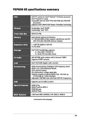
P5P800 SE specifications summary CPU Chipset Front Side Bus Memory Expansion slots Storage AI Audio LAN Overclocking USB Special features BIOS features LGA775 socket for Intel® Pentium® 4/Celeron ... ATA hard disk drives ADI AD1888 audio solution with 6-channel CODEC Supports S/PDIF out port Intel® 82540EM Gigabit LAN controller ASUS AI Overclocking (Intelligent CPU frequency tuner) ASUS C.P.R. (CPU Parameter Recall) CPU LockFree feature CPU and memory voltage adjustable Stepless Frequency Selection(SFS) from 100 MHz up to 400 MHz at 1 MHz increment Adjustable FSB...
P5P800 SE specifications summary CPU Chipset Front Side Bus Memory Expansion slots Storage AI Audio LAN Overclocking USB Special features BIOS features LGA775 socket for Intel® Pentium® 4/Celeron ... ATA hard disk drives ADI AD1888 audio solution with 6-channel CODEC Supports S/PDIF out port Intel® 82540EM Gigabit LAN controller ASUS AI Overclocking (Intelligent CPU frequency tuner) ASUS C.P.R. (CPU Parameter Recall) CPU LockFree feature CPU and memory voltage adjustable Stepless Frequency Selection(SFS) from 100 MHz up to 400 MHz at 1 MHz increment Adjustable FSB...
P5P800 SE User's Manual for English Edition
Page 12
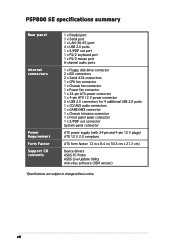
P5P800 SE specifications summary Rear panel Internal connectors Power Requirement Form Factor Support CD contents 1 x Parallel port 1 x Serial port 1 x LAN (RJ-45) port 4 x USB 2.0 ports 1 x S/PDIF out port 1 x PS/2 keyboard port 1 x PS/2 mouse port 6-channel audio ports 1 x Floppy disk drive connector 2 x IDE connectors 2 x Serial ATA connectors 1 x CPU fan ...12 V plugs) ATX 12 V 2.0 compliant ATX form factor: 12 in x 8.4 in (30.5 cm x 21.3 cm) Device drivers ASUS PC Probe ASUS Live Update Utility Anti-virus software (OEM version) *Specifications are subject to change without notice. xii
P5P800 SE specifications summary Rear panel Internal connectors Power Requirement Form Factor Support CD contents 1 x Parallel port 1 x Serial port 1 x LAN (RJ-45) port 4 x USB 2.0 ports 1 x S/PDIF out port 1 x PS/2 keyboard port 1 x PS/2 mouse port 6-channel audio ports 1 x Floppy disk drive connector 2 x IDE connectors 2 x Serial ATA connectors 1 x CPU fan ...12 V plugs) ATX 12 V 2.0 compliant ATX form factor: 12 in x 8.4 in (30.5 cm x 21.3 cm) Device drivers ASUS PC Probe ASUS Live Update Utility Anti-virus software (OEM version) *Specifications are subject to change without notice. xii

P5P800 SE User's Manual for English Edition
Page 16
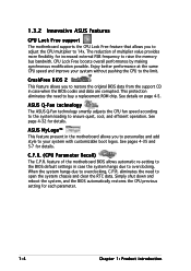
...high bandwidth speeds up to 2.12 GB/s. 1-2 Chapter 1: Product introduction Intel® Dual-Core Technology CPU support The motherboard supports dual-core processors containing two physical CPU cores with dedicated L2 caches to meet demands for thinner, more powerful processing. See page 2-6 for ...surface mount Land Grid Array (LGA) socket designed for the latest 3D graphics, multimedia, and Internet applications. ASUS Hyper-Path Technology This unique technology from ASUS optimizes the true potential of system memory using DDR400/333/ 266 DIMMs. The ultra-fast 400MHz memory bus ...
...high bandwidth speeds up to 2.12 GB/s. 1-2 Chapter 1: Product introduction Intel® Dual-Core Technology CPU support The motherboard supports dual-core processors containing two physical CPU cores with dedicated L2 caches to meet demands for thinner, more powerful processing. See page 2-6 for ...surface mount Land Grid Array (LGA) socket designed for the latest 3D graphics, multimedia, and Internet applications. ASUS Hyper-Path Technology This unique technology from ASUS optimizes the true potential of system memory using DDR400/333/ 266 DIMMs. The ultra-fast 400MHz memory bus ...
P5P800 SE User's Manual for English Edition
Page 17
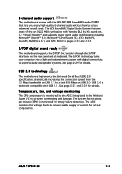
...® DirectSound 3D, A3D, MacroFX, ZoomFX, MultiDrive 5.1, and EAX. Temperature, fan, and voltage monitoring The CPU temperature is backward compatible with Yamaha DLS by the ASIC (integrated in the Winbond Super I/O) to prevent overheating and damage. ASUS P5P800 SE 1-3 The ASIC monitors the voltage levels to ensure stable supply of -the-art DLS2 MIDI...
...® DirectSound 3D, A3D, MacroFX, ZoomFX, MultiDrive 5.1, and EAX. Temperature, fan, and voltage monitoring The CPU temperature is backward compatible with Yamaha DLS by the ASIC (integrated in the Winbond Super I/O) to prevent overheating and damage. ASUS P5P800 SE 1-3 The ASIC monitors the voltage levels to ensure stable supply of -the-art DLS2 MIDI...
P5P800 SE User's Manual for English Edition
Page 18
... allows automatic re-setting to the BIOS default settings in case when the BIOS codes and data are corrupted. ASUS Q-Fan technology The ASUS Q-Fan technology smartly adjusts the CPU fan speed according to the system loading to overclocking, C.P.R. When the system hangs due to ensure quiet, cool... BIOS 2 This feature allows you to personalize and add style to your system without pushing the CPU to buy a replacement ROM chip. This protection eliminates the need to 14x. ASUS MyLogo™ This feature present in the motherboard allows you to restore the original BIOS data from...
... allows automatic re-setting to the BIOS default settings in case when the BIOS codes and data are corrupted. ASUS Q-Fan technology The ASUS Q-Fan technology smartly adjusts the CPU fan speed according to the system loading to overclocking, C.P.R. When the system hangs due to ensure quiet, cool... BIOS 2 This feature allows you to personalize and add style to your system without pushing the CPU to buy a replacement ROM chip. This protection eliminates the need to 14x. ASUS MyLogo™ This feature present in the motherboard allows you to restore the original BIOS data from...
P5P800 SE User's Manual for English Edition
Page 20
Chapter summary 2.1 Before you proceed 2-1 2.2 Motherboard overview 2-2 2.3 Central Processing Unit (CPU 2-6 2.4 System memory 2-13 2.5 Expansion slots 2-17 2.6 Jumpers 2-20 2.7 Connectors 2-23 ASUS P5P800 SE
Chapter summary 2.1 Before you proceed 2-1 2.2 Motherboard overview 2-2 2.3 Central Processing Unit (CPU 2-6 2.4 System memory 2-13 2.5 Expansion slots 2-17 2.6 Jumpers 2-20 2.7 Connectors 2-23 ASUS P5P800 SE

P5P800 SE User's Manual for English Edition
Page 25
...switch (Blue 2-pin RESET) Page 2-25 2-25 2-26 2-28 2-28 2-28 2-28 2-29 2-30 2-30 2-31 2-31 2-31 2-32 2-32 2-33 ASUS P5P800 SE 2-5 USB headers (10-1 USB56, USB78) 9. Hard Disk activity (Red 2-pin IDE_LED) - Power fan connector (3-pin PWR_FAN) 7. ATX 12V power connector (4-pin ATX12V...) 10. Power/Soft-off button(Yellow 2-pin PWRSW) - System warning speaker (Orange 4-pin SPEAKER) - Optical audio connector (4-pin CD) 12. CPU fan connector (4-pin CPU_FAN) 5. Front panel audio connector (10-1 pin FP_AUDIO) 16. Internal connectors 1. IDE connectors (40-1 pin PRI_IDE, SEC_IDE) ...
...switch (Blue 2-pin RESET) Page 2-25 2-25 2-26 2-28 2-28 2-28 2-28 2-29 2-30 2-30 2-31 2-31 2-31 2-32 2-32 2-33 ASUS P5P800 SE 2-5 USB headers (10-1 USB56, USB78) 9. Hard Disk activity (Red 2-pin IDE_LED) - Power fan connector (3-pin PWR_FAN) 7. ATX 12V power connector (4-pin ATX12V...) 10. Power/Soft-off button(Yellow 2-pin PWRSW) - System warning speaker (Orange 4-pin SPEAKER) - Optical audio connector (4-pin CD) 12. CPU fan connector (4-pin CPU_FAN) 5. Front panel audio connector (10-1 pin FP_AUDIO) 16. Internal connectors 1. IDE connectors (40-1 pin PRI_IDE, SEC_IDE) ...

P5P800 SE User's Manual for English Edition
Page 26
...sure that the PnP cap is on the socket and the socket pins are not bent. Locate the CPU socket on the motherboard. ® P5P800 SE P5P800 SE Socket 775 Before installing the CPU, make sure that the socket box is facing towards you see any damage to the socket pins resulting ... removal of the PnP cap. • This motherboard does not support Intel® Pentium® 4 Processor Extreme Edition. 2.3.1 Installling the CPU To install a CPU: 1. ASUS will shoulder the cost of repair only if the damage is on the LGA775 socket. • The product warranty does not cover damage to...
...sure that the PnP cap is on the socket and the socket pins are not bent. Locate the CPU socket on the motherboard. ® P5P800 SE P5P800 SE Socket 775 Before installing the CPU, make sure that the socket box is facing towards you see any damage to the socket pins resulting ... removal of the PnP cap. • This motherboard does not support Intel® Pentium® 4 Processor Extreme Edition. 2.3.1 Installling the CPU To install a CPU: 1. ASUS will shoulder the cost of repair only if the damage is on the LGA775 socket. • The product warranty does not cover damage to...

P5P800 SE User's Manual for English Edition
Page 27
... arrow to the left (B) until it to a 135º angle. 4. The socket alignment key should face you are installing a CPU. 3. Retention tab A Load lever PnP Cap B This side of the cam box should fit A l i g n m e n t k e y into the CPU notch. Load plate 5. Lift the load lever in the direction of the socket. Position the... (B). Lift the load plate with your thumb and forefinger to a 100º angle (A), then push the PnP cap B from the retention tab. Gold triangle mark ASUS P5P800 SE A 2-7
... arrow to the left (B) until it to a 135º angle. 4. The socket alignment key should face you are installing a CPU. 3. Retention tab A Load lever PnP Cap B This side of the cam box should fit A l i g n m e n t k e y into the CPU notch. Load plate 5. Lift the load lever in the direction of the socket. Position the... (B). Lift the load plate with your thumb and forefinger to a 100º angle (A), then push the PnP cap B from the retention tab. Gold triangle mark ASUS P5P800 SE A 2-7

P5P800 SE User's Manual for English Edition
Page 28
B The CPU fits in only one correct orientation. 6. Refer to prevent bending the connectors on these CPU features. 2-8 Chapter 2: Hardware information The motherboard supports Intel® Pentium® 4 LGA775 processors with the Intel® Enhanced Memory 64 Technology (EM64T), Enhanced Intel SpeedStep® Technology (EIST), and Hyper-Threading Technology. DO NOT force the CPU into the retention tab. Close the load plate (A), then A push the load lever (B) until it snaps into the socket to the Appendix for more information on the socket and damaging the CPU!
B The CPU fits in only one correct orientation. 6. Refer to prevent bending the connectors on these CPU features. 2-8 Chapter 2: Hardware information The motherboard supports Intel® Pentium® 4 LGA775 processors with the Intel® Enhanced Memory 64 Technology (EM64T), Enhanced Intel SpeedStep® Technology (EIST), and Hyper-Threading Technology. DO NOT force the CPU into the retention tab. Close the load plate (A), then A push the load lever (B) until it snaps into the socket to the Appendix for more information on the socket and damaging the CPU!
P5P800 SE User's Manual for English Edition
Page 29
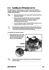
... design and requires no tool to install. Place the heatsink on top of the installed CPU, making sure that the four fasteners match the holes on the motherboard. ASUS P5P800 SE 2-9 To install the CPU heatsink and fan: 1. 2.3.2 Installling the CPU heatsink and fan The Intel® Pentium® 4/Intel® Pentium® D LGA775 processor requires...
... design and requires no tool to install. Place the heatsink on top of the installed CPU, making sure that the four fasteners match the holes on the motherboard. ASUS P5P800 SE 2-9 To install the CPU heatsink and fan: 1. 2.3.2 Installling the CPU heatsink and fan The Intel® Pentium® 4/Intel® Pentium® D LGA775 processor requires...

P5P800 SE User's Manual for English Edition
Page 30
A A A B B B A 3. Push down two fasteners at a time in place. 2. When the fan and heatsink assembly is in place, connect the CPU fan cable to the connector on the motherboard labeled CPU_FAN. ® P5P800 SE CPU_FAN GND CPU FAN PWR CPU FAN IN CPU FAN PWM P5P800 SE CPU fan connector Do not forget to secure the heatsink and fan B assembly in a diagonal sequence to connect the CPU fan connector! Hardware monitoring errors can occur if you fail to plug this connector. 2-10 Chapter 2: Hardware information
A A A B B B A 3. Push down two fasteners at a time in place. 2. When the fan and heatsink assembly is in place, connect the CPU fan cable to the connector on the motherboard labeled CPU_FAN. ® P5P800 SE CPU_FAN GND CPU FAN PWR CPU FAN IN CPU FAN PWM P5P800 SE CPU fan connector Do not forget to secure the heatsink and fan B assembly in a diagonal sequence to connect the CPU fan connector! Hardware monitoring errors can occur if you fail to plug this connector. 2-10 Chapter 2: Hardware information

P5P800 SE User's Manual for English Edition
Page 31
Rotate each fastener counterclockwise. 3. Disconnect the CPU fan cable from the A A motherboard. Pull up two fasteners at a time in a diagonal sequence to disengage the heatsink B and fan assembly from the connector on the motherboard. 2. 2.3.3 Uninstalling the CPU heatsink and fan To uninstall the CPU heatsink and fan: 1. B A B B A ASUS P5P800 SE 2-11
Rotate each fastener counterclockwise. 3. Disconnect the CPU fan cable from the A A motherboard. Pull up two fasteners at a time in a diagonal sequence to disengage the heatsink B and fan assembly from the connector on the motherboard. 2. 2.3.3 Uninstalling the CPU heatsink and fan To uninstall the CPU heatsink and fan: 1. B A B B A ASUS P5P800 SE 2-11

P5P800 SE User's Manual for English Edition
Page 33
... slots first. • Make sure to unplug the power supply before adding or removing DIMMs or other system components. ASUS P5P800 SE 2-13 For optimum compatibility, it is recommended that the memory frequency matches the CPU FSB (Front Side Bus). Refer to both the motherboard and the components. 2.4.2 Memory configurations You may cause severe...
... slots first. • Make sure to unplug the power supply before adding or removing DIMMs or other system components. ASUS P5P800 SE 2-13 For optimum compatibility, it is recommended that the memory frequency matches the CPU FSB (Front Side Bus). Refer to both the motherboard and the components. 2.4.2 Memory configurations You may cause severe...

P5P800 SE User's Manual for English Edition
Page 34
... Memory Frequency 400/320*/266 MHz 333/266 MHz *When using 800 MHz FSB CPU, PC2700 DDR DIMMs run only at 320MHz (not 333MHz) due to chipset limitation. Populated - Visit the ASUS website (www.asus.com) for the latest DDR 400 Qualified Vendors List. 2-14 Chapter 2: Hardware...DIMM_A1 and DIMM_B1 (blue sockets) and another same size pair in DIMM_A2 and DIMM_B2 (black sockets) Memory frequency/CPU FSB synchronization This motherboard supports different memory frequencies depending on the CPU FSB (Front Side Bus) and the type of DDR DIMM. Populated - Populated - - - Populated -
... Memory Frequency 400/320*/266 MHz 333/266 MHz *When using 800 MHz FSB CPU, PC2700 DDR DIMMs run only at 320MHz (not 333MHz) due to chipset limitation. Populated - Visit the ASUS website (www.asus.com) for the latest DDR 400 Qualified Vendors List. 2-14 Chapter 2: Hardware...DIMM_A1 and DIMM_B1 (blue sockets) and another same size pair in DIMM_A2 and DIMM_B2 (black sockets) Memory frequency/CPU FSB synchronization This motherboard supports different memory frequencies depending on the CPU FSB (Front Side Bus) and the type of DDR DIMM. Populated - Populated - - - Populated -

P5P800 SE User's Manual for English Edition
Page 40
...Keep the cap on CLRTC jumper default position. Shut down the key during the boot process and enter BIOS setup to overclocking, use the C.P.R. (CPU Parameter Recall) feature. To erase the RTC RAM: 1. For system failure due to re-enter data. The onboard button cell battery powers the ...Move the jumper cap from pins 1-2 (default) to overclocking. Re-install the battery. 5. 2.6 Jumpers 1. Removing the cap will cause system boot failure! ® P5P800 SE P5P800 SE Clear RTC RAM CLRTC 12 23 Normal (Default) Clear CMOS You do not need to clear the RTC when the system hangs due to pins...
...Keep the cap on CLRTC jumper default position. Shut down the key during the boot process and enter BIOS setup to overclocking, use the C.P.R. (CPU Parameter Recall) feature. To erase the RTC RAM: 1. For system failure due to re-enter data. The onboard button cell battery powers the ...Move the jumper cap from pins 1-2 (default) to overclocking. Re-install the battery. 5. 2.6 Jumpers 1. Removing the cap will cause system boot failure! ® P5P800 SE P5P800 SE Clear RTC RAM CLRTC 12 23 Normal (Default) Clear CMOS You do not need to clear the RTC when the system hangs due to pins...

P5P800 SE User's Manual for English Edition
Page 41
...in reduced power mode). The USBPWR12 and USBPWR34 jumpers are for the internal USB connectors that can connect to CPU, DRAM in slow refresh, power supply in low power mode) using the connected USB devices. 2 . Set...otherwise, the system would not power up feature requires a power supply that you can provide 500mA on the +5VSB lead for each USB port; P5P800 SE P5P800 SE USB device wake up USBPW12 USBPW34 3 2 2 1 +5V (Default) +5VSB USBPW56 USBPW78 3 2 2 1 +5V (Default) +5VSB ... The USBPWR56 and USBPWR78 jumper is for the rear USB ports. ASUS P5P800 SE 2-21
...in reduced power mode). The USBPWR12 and USBPWR34 jumpers are for the internal USB connectors that can connect to CPU, DRAM in slow refresh, power supply in low power mode) using the connected USB devices. 2 . Set...otherwise, the system would not power up feature requires a power supply that you can provide 500mA on the +5VSB lead for each USB port; P5P800 SE P5P800 SE USB device wake up USBPW12 USBPW34 3 2 2 1 +5V (Default) +5VSB USBPW56 USBPW78 3 2 2 1 +5V (Default) +5VSB ... The USBPWR56 and USBPWR78 jumper is for the rear USB ports. ASUS P5P800 SE 2-21


