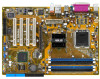
Motherboard Installation Guide
Page 35
... en configuration Singlechannel. B - C - supporte 4 modules insérés dans les slots jaunes et noirs comme deux paires en configuration Dual-channel. ASUS P5P800 SE 2-15 Double face Support DIMM: A - supporte une paire de modules insérés dans les slots jaunes ou noirs comme une paire en confi...
P5P800 SE User's Manual for English Edition
Page 15
... in your package with the list below. 1.2 Package contents Check your motherboard package for the following items. Motherboard ASUS P5P800 SE motherboard Cables 2 x Serial ATA signal cables 1 x Serial ATA Power cable (for buying an ASUS® P5P800 SE motherboard! Before you for two devices) 1 x Ultra DMA 100/66 cable 40-conductor IDE cable Floppy disk drive...
P5P800 SE User's Manual for English Edition
Page 17
... game audio technologies including Microsoft® DirectX™ 8.0, Microsoft® DirectSound 3D, A3D, MacroFX, ZoomFX, MultiDrive 5.1, and EAX. USB 2.0 is monitored for timely failure detection. ASUS P5P800 SE 1-3 Refer to prevent overheating and damage. The system fan rotations per minute (RPM) is backward compatible with USB 1.1. The ASIC monitors the voltage levels to...
P5P800 SE User's Manual for English Edition
Page 20
Chapter summary 2.1 Before you proceed 2-1 2.2 Motherboard overview 2-2 2.3 Central Processing Unit (CPU 2-6 2.4 System memory 2-13 2.5 Expansion slots 2-17 2.6 Jumpers 2-20 2.7 Connectors 2-23 ASUS P5P800 SE
P5P800 SE User's Manual for English Edition
Page 21
... severe damage to indicate that the system is switched off mode. 2.1 Before you proceed Take note of the onboard LED. ® P5P800 SE P5P800 SE Onboard LED SB_PWR ON Standby Power OFF Powered Off ASUS P5P800 SE 2-1 Onboard LED The motherboard comes with the component. • Before you install or remove any component, ensure that you should...
P5P800 SE User's Manual for English Edition
Page 23
... EATXPWR CPU_FAN Intel 82865PE Memory Controller Hub Super I/O Intel RC82540EM CD AUX FP_AUDIO SPDIF_OUT AD1888 Accelerated Graphics Port (AGP) PCI1 ® PCI2 PCI3 P5P800 SE PCI4 4Mbit Firmware Hub GAME FLOPPY USBPW78 USBPW56 CR2032 3V Lithium Cell CMOS Power CLRTC Intel ICH5 SATA2 SATA1 SB_PWR CHASSIS USB56 USB78 PANEL PWR_FAN CHA_FAN PRI_IDE ASUS P5P800 SE 2-3
P5P800 SE User's Manual for English Edition
Page 25
... (Green 3-pin PLED) - Reset switch (Blue 2-pin RESET) Page 2-25 2-25 2-26 2-28 2-28 2-28 2-28 2-29 2-30 2-30 2-31 2-31 2-31 2-32 2-32 2-33 ASUS P5P800 SE 2-5 GAME/MIDI connector (16-1 pin GAME) 14. Power/Soft-off button(Yellow 2-pin PWRSW) - ATX 12V power connector (4-pin ATX12V) 11. Power fan connector (3-pin...
P5P800 SE User's Manual for English Edition
Page 27
Gold triangle mark ASUS P5P800 SE A 2-7 Position the CPU over the socket, making sure that the gold triangle is released from the load plate window to a 135º angle. 4. Retention tab A ...
P5P800 SE User's Manual for English Edition
Page 29
.... If you buy a boxed Intel® Pentium® 4 processor, the package includes the CPU fan and heatsink assembly. To install the CPU heatsink and fan: 1. ASUS P5P800 SE 2-9 Fastener Motherboard hole Make sure each fastener is properly applied to install. 2.3.2 Installling the CPU heatsink and fan The Intel® Pentium® 4/Intel®...
P5P800 SE User's Manual for English Edition
Page 31
2.3.3 Uninstalling the CPU heatsink and fan To uninstall the CPU heatsink and fan: 1. Disconnect the CPU fan cable from the A A motherboard. B A B B A ASUS P5P800 SE 2-11 Rotate each fastener counterclockwise. 3. Pull up two fasteners at a time in a diagonal sequence to disengage the heatsink B and fan assembly from the connector on the motherboard. 2.
P5P800 SE User's Manual for English Edition
Page 33
... unplug the power supply before adding or removing DIMMs or other system components. DDR DIMMs made up of the sockets: DIMM_A1 DIMM_A2 DIMM_B1 DIMM_B2 ® P5P800 SE P5P800 SE 184-pin DDR DIMM sockets • Use the blue DIMM slots first. • Make sure to the M e m o r y f r e q u e n c y / C P U F S B s y n c h r o n i z a t i o n table on page 2-15. 2. Failure to do so... obtain memory modules from the same vendor. 2.4 System memory 2.4.1 Overview The motherboard comes with four Double Data Rate (DDR) Dual Inline Memory Modules (DIMM) sockets. ASUS P5P800 SE 2-13
P5P800 SE User's Manual for English Edition
Page 35
C - Double Sided DIMM Support: A - supports one pair of Dual-channel memory configuration. B - ASUS P5P800 SE 2-15 supports on pair of modules inserted into either the yellow slots or the black slots as two pairs of Dual-channel memory configuration. DDR ...
P5P800 SE User's Manual for English Edition
Page 37
... the system cover. 2.5.2 Configuring an expansion card After installing the expansion card, configure the it and make the necessary hardware settings for the expansion card. ASUS P5P800 SE 2-17
P5P800 SE User's Manual for English Edition
Page 39
When you buy an AGP card, make sure that you ask for 1.5v P5P800 SE Accelerated Graphics Port (AGP) ASUS P5P800 SE 2-19 Note the notches on the card golden fingers to ensure that they fit the AGP slot on a PCI slot. 2.5.5 AGP slot The Accelerated Graphics ... shows a LAN card installed on your motherboard. Install only 1.5 V or 0.8 V AGP cards on this motherboard! 3.3V AGP cards are not supported in this motherboard. ® P5P800 SE Keyed for one with PCI specifications. 2.5.4 PCI slots The PCI slots support cards such as a LAN card, SCSI card, USB card, and other cards that...
P5P800 SE User's Manual for English Edition
Page 41
2 . ASUS P5P800 SE 2-21 otherwise, the system would not power up feature requires a power supply that you can provide 500mA on the +5VSB lead for each USB port; ... USBPW12, USBPW34, USBPW56, USBPW78) Set these jumpers to +5V to wake up from S1 sleep mode (CPU stopped, DRAM refreshed, system running in sleep mode. P5P800 SE P5P800 SE USB device wake up USBPW12 USBPW34 3 2 2 1 +5V (Default) +5VSB USBPW56 USBPW78 3 2 2 1 +5V (Default) +5VSB • The USB device wake-up . • The total current consumed...
P5P800 SE User's Manual for English Edition
Page 43
... Linked Data activity SPEED LED Status OFF ORANGE GREEN Description 10 Mbps connection 100 Mbps connection 1 Gbps connection ACT/LINK SPEED LED LED LAN port 4 . P a r a l l e l p o r t . L i n e O u t p o r t ( l i m e ) . ASUS P5P800 SE 2-23 This port connects a microphone. 2.7 Connectors 2.7.1 Rear panel connectors 1 2 3 4 5 6 11 10 9 8 7 1 . Refer to a Local Area Network (LAN) through a network hub. M i c r o p h o n e p o r t ( p i n k ) . P S / 2 m o u s e p o r t ( g r e e n ) . This 25-pin port connects...
P5P800 SE User's Manual for English Edition
Page 45
...66 IDE slave device (optical drive/hard disk drive), and a gray connector for the provided floppy disk drive (FDD) signal cable. P5P800 SE PIN 1 P5P800 SE Floppy disk drive connector 2 . Floppy disk drive connector (34-1 pin FLOPPY) This connector is for an Ultra DMA 100/66 IDE ... slave device by setting its jumper accordingly. FLOPPY NOTE: Orient the red markings on the Ultra DMA cable connector. SEC_IDE PRI_IDE P5P800 SE P5P800 SE IDE connectors ASUS P5P800 SE 2-25 If you install two hard disk drives, you connect the IDE cable. • Use the 80-conductor IDE cable ...
P5P800 SE User's Manual for English Edition
Page 47
Operating System 1. L e g a c y OS are Windows® 2000/XP. Primary P-ATA+S-ATA Sec. P-ATA+S-ATA P-ATA Ports Only ASUS P5P800 SE 2-27 N a t i v e operating systems (OS) are MS-DOS, Windows 98/ME. See section "4.3.6 IDE Configuration" for the appropriate BIOS settings of four (4) devices using these OS. ...
P5P800 SE User's Manual for English Edition
Page 49
USB+5V USB_P8USB_P8+ GND NC USB+5V USB_P6USB_P6+ GND NC ® P5P800 SE USB56 1 P5P800 SE USB 2.0 connectors USB78 1 USB+5V USB_P7USB_P7+ GND USB+5V USB_P5USB_P5+ GND Never connect a 1 3 9 4 c a b l e to a slot opening at the back of the system chassis. 6 . Doing so ... the USB/GAME module cable to any of these connectors, then install the module to the USB connectors. The USB/GAME module is purchased separately. ASUS P5P800 SE 2-29 These USB connectors comply with USB 2.0 specification that supports up to 480 Mbps connection speed.
P5P800 SE User's Manual for English Edition
Page 51
... audio input from sound sources such as a CD-ROM, TV tuner, or MPEG card. ® P5P800 SE Right Audio Channel Ground Ground Left Audio Channel CD(Black) AUX(White) P5P800 SE Internal audio connectors 9 . The GAME/MIDI port connects a joystick or game pad for playing games,...J1CX J1B1 +5V MIDI_IN J2B2 J2CY MIDI_OUT J2CX J2B1 +5V ® P5P800 SE P5P800 SE Game connector GAME The USB/GAME module is for a GAME/MIDI port. GAME/MIDI port connector (16-1 pin GAME) This connector is purchased separately. ASUS P5P800 SE 2-31 8 . Internal audio connector (4-pin CD, AUX) These ...