
User Manual
Page 1
P5KPL SE Motherboard
P5KPL SE Motherboard
User Manual
Page 3
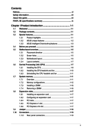
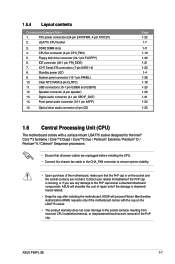
Contents Notices...vi Safety information vii About this guide vii P5KPL SE specifications summary ix Chapter 1Product introduction 1-1 1.1 Welcome 1-1 1.2 Package contents 1-1 1.3 Special features 1-1 1.3.1 Product highlights 1-1 1.3.2 ASUS unique features 1-2 1.3.3 ASUS Intelligent Overclocking features 1-3 1.4 Before you proceed 1-4 1.5 Motherboard overview 1-5 1.5.1 Placement direction 1-5 1.5.2 Screw holes 1-5 1.5.3 Motherboard layout 1-6 1.5.4 Layout contents 1-7 1.6 Central Processing Unit (CPU 1-7 1.6.1 Installing the CPU 1-8 1.6.2 Installing the ...
Contents Notices...vi Safety information vii About this guide vii P5KPL SE specifications summary ix Chapter 1Product introduction 1-1 1.1 Welcome 1-1 1.2 Package contents 1-1 1.3 Special features 1-1 1.3.1 Product highlights 1-1 1.3.2 ASUS unique features 1-2 1.3.3 ASUS Intelligent Overclocking features 1-3 1.4 Before you proceed 1-4 1.5 Motherboard overview 1-5 1.5.1 Placement direction 1-5 1.5.2 Screw holes 1-5 1.5.3 Motherboard layout 1-6 1.5.4 Layout contents 1-7 1.6 Central Processing Unit (CPU 1-7 1.6.1 Installing the CPU 1-8 1.6.2 Installing the ...
User Manual
Page 9
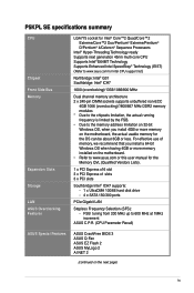
...; ICH7 supports: - 1 x UltraDMA 100/66 hard disk drive - 4 x SATA 150/300 ports PCIe Gigabit LAN Stepless Frequency Selection (SFS): - P5KPL SE specifications summary CPU. Chipset Front Side Bus Memory Expansion Slots Storage LAN ASUS Overclocking Features LGA775 socket for Intel® Core™2 Quad/Core™2 Extreme/Core™2 Duo/Pentium® Extreme...
...; ICH7 supports: - 1 x UltraDMA 100/66 hard disk drive - 4 x SATA 150/300 ports PCIe Gigabit LAN Stepless Frequency Selection (SFS): - P5KPL SE specifications summary CPU. Chipset Front Side Bus Memory Expansion Slots Storage LAN ASUS Overclocking Features LGA775 socket for Intel® Core™2 Quad/Core™2 Extreme/Core™2 Duo/Pentium® Extreme...
User Manual
Page 10
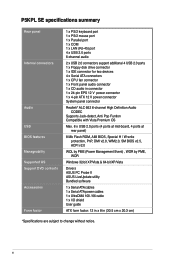
P5KPL SE specifications summary Rear panel Internal connectors Audio USB BIOS features Manageability Supported OS Support DVD contents Accessories Form factor 1 x PS/2 keyboard port 1 x PS/2 mouse port 1 x ... BIOS v2.5, ACPI v2.0 WOL by PME (Power Management Event) , WOR by PME, WOR Windows 32-bit XP/Vista & 64-bit XP/Vista Drivers ASUS PC Probe II ASUS LiveUpdate utility Bundled software 1 x Serial ATA cables 1 x Serial ATA power cables 1 x UltraDMA 100 / 66 cable 1 x I/O shield User guide ATX form factor: 12 in...
P5KPL SE specifications summary Rear panel Internal connectors Audio USB BIOS features Manageability Supported OS Support DVD contents Accessories Form factor 1 x PS/2 keyboard port 1 x PS/2 mouse port 1 x ... BIOS v2.5, ACPI v2.0 WOL by PME (Power Management Event) , WOR by PME, WOR Windows 32-bit XP/Vista & 64-bit XP/Vista Drivers ASUS PC Probe II ASUS LiveUpdate utility Bundled software 1 x Serial ATA cables 1 x Serial ATA power cables 1 x UltraDMA 100 / 66 cable 1 x I/O shield User guide ATX form factor: 12 in...
User Manual
Page 11
...1.1 Welcome! Before you for the following items. Motherboard Cables Accessories Application DVD Documentation ASUS P5KPL SE motherboard 1 x Serial ATA cable 1 x Ultra DMA 100/66 cable 1 x SATA power cable 1 x I/O shield ASUS motherboard support DVD User Manual If any of the above items is damaged or missing... processors from Intel. Combined with the list below. 1.2 Package contents Check your motherboard package for buying an ASUS® P5KPL SE motherboard! This is based on the use of gaming experience and multi-tasking performance. The motherboard delivers a ...
...1.1 Welcome! Before you for the following items. Motherboard Cables Accessories Application DVD Documentation ASUS P5KPL SE motherboard 1 x Serial ATA cable 1 x Ultra DMA 100/66 cable 1 x SATA power cable 1 x I/O shield ASUS motherboard support DVD User Manual If any of the above items is damaged or missing... processors from Intel. Combined with the list below. 1.2 Package contents Check your motherboard package for buying an ASUS® P5KPL SE motherboard! This is based on the use of gaming experience and multi-tasking performance. The motherboard delivers a ...
User Manual
Page 13
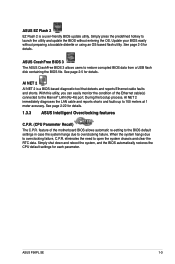
... the system chassis and clear the RTC data. eliminates the need to overclocking failure, C.P.R. See page 2-3 for details. 1.3.3 ASUS Intelligent Overclocking features C.P.R. (CPU Parameter Recall) The C.P.R. With this utility, you can easily monitor the condition of the motherboard ... of the Ethernet cable(s) connected to overclocking failure. See page 2-22 for details. ASUS P5KPL SE 1-3 ASUS CrashFree BIOS 3 The ASUS CrashFree BIOS 3 allows users to 100 meters at 1 meter accuracy. ASUS EZ Flash 2 EZ Flash 2 is a BIOS-based diagnostic tool that detects and reports...
... the system chassis and clear the RTC data. eliminates the need to overclocking failure, C.P.R. See page 2-3 for details. 1.3.3 ASUS Intelligent Overclocking features C.P.R. (CPU Parameter Recall) The C.P.R. With this utility, you can easily monitor the condition of the motherboard ... of the Ethernet cable(s) connected to overclocking failure. See page 2-22 for details. ASUS P5KPL SE 1-3 ASUS CrashFree BIOS 3 The ASUS CrashFree BIOS 3 allows users to 100 meters at 1 meter accuracy. ASUS EZ Flash 2 EZ Flash 2 is a BIOS-based diagnostic tool that detects and reports...
User Manual
Page 14
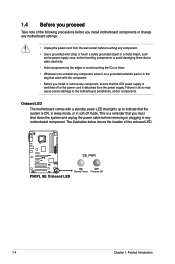
... the location of the following precautions before you install motherboard components or change any motherboard component. 1.4 Before you proceed Take note of the onboard LED. P5KPL SE SB_PWR P5KPL SE Onboard LED ON OFF Standy Power Powered Off 1-4 Chapter 1: Product introduction This is switched off mode. Onboard LED The motherboard comes with the component...
... the location of the following precautions before you install motherboard components or change any motherboard component. 1.4 Before you proceed Take note of the onboard LED. P5KPL SE SB_PWR P5KPL SE Onboard LED ON OFF Standy Power Powered Off 1-4 Chapter 1: Product introduction This is switched off mode. Onboard LED The motherboard comes with the component...
User Manual
Page 15
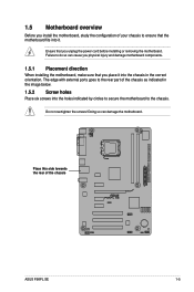
.... The edge with external ports goes to the rear part of your chassis to do so can damage the motherboard. the rear of the chassis P5KPL SE ASUS P5KPL SE 1-5 Failure to ensure that you place it . Do not overtighten the screws!
.... The edge with external ports goes to the rear part of your chassis to do so can damage the motherboard. the rear of the chassis P5KPL SE ASUS P5KPL SE 1-5 Failure to ensure that you place it . Do not overtighten the screws!
User Manual
Page 16
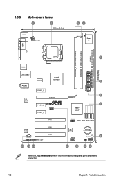
... DIMM_A1 (64bit, 240-pin module) FLOPPY LGA775 5 USB34 30.5cm(12in) LAN1_USB12 Intel® ICS G31 B0 9LPRS954A3GLF 6 AUDIO EATXPWR PRI_IDE PCIEX1_1 1 PCIEX16 RTL 8111C P5KPL SE PCIEX1_2 7 PCIEX1_3 SPEAKER Intel® ICH7 PCI1 USB56 SATA1 SATA3 SATA2 SATA4 ALC662 CD AAFP SPDIF_OUT 15 14 13 PCI2 PCI3 8Mb BIOS Lithium Cell...
... DIMM_A1 (64bit, 240-pin module) FLOPPY LGA775 5 USB34 30.5cm(12in) LAN1_USB12 Intel® ICS G31 B0 9LPRS954A3GLF 6 AUDIO EATXPWR PRI_IDE PCIEX1_1 1 PCIEX16 RTL 8111C P5KPL SE PCIEX1_2 7 PCIEX1_3 SPEAKER Intel® ICH7 PCI1 USB56 SATA1 SATA3 SATA2 SATA4 ALC662 CD AAFP SPDIF_OUT 15 14 13 PCI2 PCI3 8Mb BIOS Lithium Cell...
User Manual
Page 17
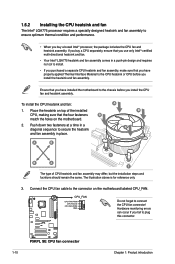
... the chassis fan cable to the CHA_FAN connector to ensure system stability. • Upon purchase of the PnP cap. ASUS will process Return Merchandise Authorization (RMA) requests only if the motherboard comes with a surface mount LGA775 socket designed for the... Celeron® Sequence processors. • Ensure that the PnP cap is shipment/ transit-related. • Keep the cap after installing the motherboard. ASUS P5KPL SE 1-7 ATX power connectors (24-pin EATXPWR, 4-pin ATX12V) 2. Front panel audio connector (10-1 pin AAFP) 15. DDR2 DIMM slots 4. 1.5.4 Layout ...
... the chassis fan cable to the CHA_FAN connector to ensure system stability. • Upon purchase of the PnP cap. ASUS will process Return Merchandise Authorization (RMA) requests only if the motherboard comes with a surface mount LGA775 socket designed for the... Celeron® Sequence processors. • Ensure that the PnP cap is shipment/ transit-related. • Keep the cap after installing the motherboard. ASUS P5KPL SE 1-7 ATX power connectors (24-pin EATXPWR, 4-pin ATX12V) 2. Front panel audio connector (10-1 pin AAFP) 15. DDR2 DIMM slots 4. 1.5.4 Layout ...
User Manual
Page 18
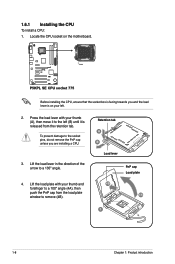
... cap Load plate 4B 4A 3 1-8 Chapter 1: Product introduction Press the load lever with your thumb (A), then move it is facing towards you are installing a CPU. 3. P5KPL SE P5KPL SE CPU socket 775 Before installing the CPU, ensure that the socket box is released from the load plate window to the left . 2.
... cap Load plate 4B 4A 3 1-8 Chapter 1: Product introduction Press the load lever with your thumb (A), then move it is facing towards you are installing a CPU. 3. P5KPL SE P5KPL SE CPU socket 775 Before installing the CPU, ensure that the socket box is released from the load plate window to the left . 2.
User Manual
Page 19
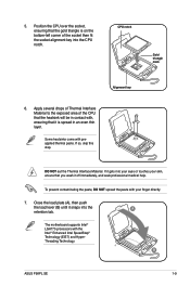
... Interface Material. Close the load plate (A), then push the load lever (B) until it gets into the A retention tab. CPU notch Gold triangle mark Alignment key 6. B ASUS P5KPL SE 1-9 5. If it snaps into your eyes or touches your finger directly. 7.
... Interface Material. Close the load plate (A), then push the load lever (B) until it gets into the A retention tab. CPU notch Gold triangle mark Alignment key 6. B ASUS P5KPL SE 1-9 5. If it snaps into your eyes or touches your finger directly. 7.
User Manual
Page 20
... the connector on the motherboard. 2. CPU_FAN CPU FAN PWM CPU FAN IN CPU FAN PWR GND Do not forget to connect the CPU fan connector! P5KPL SE P5KPL SE CPU fan connector 1-10 Chapter 1: Product introduction A B A A B 1 B A 1 The type of the installed CPU, making sure that the four fasteners B match the holes on the motherboard...
... the connector on the motherboard. 2. CPU_FAN CPU FAN PWM CPU FAN IN CPU FAN PWR GND Do not forget to connect the CPU fan connector! P5KPL SE P5KPL SE CPU fan connector 1-10 Chapter 1: Product introduction A B A A B 1 B A 1 The type of the installed CPU, making sure that the four fasteners B match the holes on the motherboard...
User Manual
Page 21
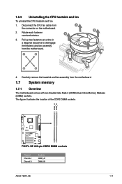
... fan To uninstall the CPU heatsink and fan 1. The figure illustrates the location of the DDR2 DIMM sockets: DIMM_A1 DIMM_B1 P5KPL SE P5KPL SE 240-pin DDR2 DIMM sockets Channel Channel A Channel B Sockets DIMM_A1 DIMM_B1 ASUS P5KPL SE 1-11 B 2. Pull up two fasteners at a time in a diagonal sequence to disengage A the heatsink and fan assembly from A the...
... fan To uninstall the CPU heatsink and fan 1. The figure illustrates the location of the DDR2 DIMM sockets: DIMM_A1 DIMM_B1 P5KPL SE P5KPL SE 240-pin DDR2 DIMM sockets Channel Channel A Channel B Sockets DIMM_A1 DIMM_B1 ASUS P5KPL SE 1-11 B 2. Pull up two fasteners at a time in a diagonal sequence to disengage A the heatsink and fan assembly from A the...

User Manual
Page 22
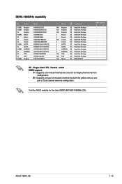
... megabit (Mb) chips or less. For optimum compatibility, it is then mapped for single-channel operation. • Always install DIMMs with the same CAS latency. P5KPL SE Motherboard Qualified Vendors Lists (QVL) DDR2-667MHz capability Size 256MB 256MB 256MB 512MB 512MB 1G 1G 1G 512MB 512MB 512MB 1G 1G 256MB 512MB 512MB...
... megabit (Mb) chips or less. For optimum compatibility, it is then mapped for single-channel operation. • Always install DIMMs with the same CAS latency. P5KPL SE Motherboard Qualified Vendors Lists (QVL) DDR2-667MHz capability Size 256MB 256MB 256MB 512MB 512MB 1G 1G 1G 512MB 512MB 512MB 1G 1G 256MB 512MB 512MB...
User Manual
Page 25
...; · · · · · · · · · · · · · · · · · SS - Visit the ASUS website for the latest DDR2-667/800/1066MHz QVL. ASUS P5KPL SE 1-15 DIMM support: • A*: Supports one module inserted into any slot as Single-channel memory configuration. • B*: Supports one pair of...
...; · · · · · · · · · · · · · · · · · SS - Visit the ASUS website for the latest DDR2-667/800/1066MHz QVL. ASUS P5KPL SE 1-15 DIMM support: • A*: Supports one module inserted into any slot as Single-channel memory configuration. • B*: Supports one pair of...

User Manual
Page 27
... an expansion card To install an expansion card: 1. Install the software drivers for information on the system and change the necessary BIOS settings, if any. ASUS P5KPL SE 1-17
... an expansion card To install an expansion card: 1. Install the software drivers for information on the system and change the necessary BIOS settings, if any. ASUS P5KPL SE 1-17
User Manual
Page 28
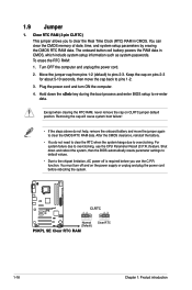
... CLRTC jumper default position. You must turn ON the computer. 4. Plug the power cord and turn off is required before rebooting the system. P5KPL SE CLRTC 12 23 Normal (Default) P5KPL SE Clear RTC RAM Clear RTC 1-18 Chapter 1: Product introduction Turn OFF the computer and unplug the power cord. 2. Shut down the key...
... CLRTC jumper default position. You must turn ON the computer. 4. Plug the power cord and turn off is required before rebooting the system. P5KPL SE CLRTC 12 23 Normal (Default) P5KPL SE Clear RTC RAM Clear RTC 1-18 Chapter 1: Product introduction Turn OFF the computer and unplug the power cord. 2. Shut down the key...

User Manual
Page 29
... 2-channel Line In Line Out Mic In 4-channel Rear Speaker Out Front Speaker Out Mic In 6-channel Rear Speaker Out Front Speaker Out Bass/Center ASUS P5KPL SE 1-19 Parallel port. In a 6-channel configuration, the function of this port allows Gigabit connection to the table below for the LAN port LED indications. This...
... 2-channel Line In Line Out Mic In 4-channel Rear Speaker Out Front Speaker Out Mic In 6-channel Rear Speaker Out Front Speaker Out Bass/Center ASUS P5KPL SE 1-19 Parallel port. In a 6-channel configuration, the function of this port allows Gigabit connection to the table below for the LAN port LED indications. This...

User Manual
Page 30
...port (purple). Floppy disk drive connector (34-1 pin FLOPPY) This connector is for connecting USB 2.0 devices. 9. P5KPL SE Floppy disk drive connector 2. SPEAKER Speaker Out GND GND +5V P5KPL SE PIN 1 P5KPL SE Speaker Out Connector 1-20 Chapter 1: Product introduction These two 4-pin Universal Serial Bus (USB) ports are available for...) signal cable. 7. USB 2.0 ports 1 and 2. USB 2.0 ports 3 and 4. This port is for connecting USB 2.0 devices. 8. FLOPPY PIN1 P5KPL SE NOTE:Orient the red markings on the connector is removed to hear system beeps and warnings.
...port (purple). Floppy disk drive connector (34-1 pin FLOPPY) This connector is for connecting USB 2.0 devices. 9. P5KPL SE Floppy disk drive connector 2. SPEAKER Speaker Out GND GND +5V P5KPL SE PIN 1 P5KPL SE Speaker Out Connector 1-20 Chapter 1: Product introduction These two 4-pin Universal Serial Bus (USB) ports are available for...) signal cable. 7. USB 2.0 ports 1 and 2. USB 2.0 ports 3 and 4. This port is for connecting USB 2.0 devices. 8. FLOPPY PIN1 P5KPL SE NOTE:Orient the red markings on the connector is removed to hear system beeps and warnings.


