User Manual
Page 3
Contents Notices...v Safety information vi About this guide vi P5KPL-AM IN/GB specifications summary viii Chapter 1: Product introduction 1.1 Before you proceed 1-1 1.2 Motherboard overview 1-2 1.2.1 Motherboard layout 1-2 1.2.2 Layout contents 1-2 1.3 Central Processing Unit (CPU 1-3 1.4 System memory 1-3 1.4.1 Overview 1-3 1.4.2 Memory configurations 1-3 1.5 Expansion slots 1-7 1.5.1 PCI slots 1-7 1.5.2 PCI Express x16 slot 1-7 1.6 Jumpers 1-7 1.7 Connectors 1-9 1.7.1 Rear panel ports 1-9 1.7.2 Internal connectors 1-10 1.8 Software...
Contents Notices...v Safety information vi About this guide vi P5KPL-AM IN/GB specifications summary viii Chapter 1: Product introduction 1.1 Before you proceed 1-1 1.2 Motherboard overview 1-2 1.2.1 Motherboard layout 1-2 1.2.2 Layout contents 1-2 1.3 Central Processing Unit (CPU 1-3 1.4 System memory 1-3 1.4.1 Overview 1-3 1.4.2 Memory configurations 1-3 1.5 Expansion slots 1-7 1.5.1 PCI slots 1-7 1.5.2 PCI Express x16 slot 1-7 1.6 Jumpers 1-7 1.7 Connectors 1-9 1.7.1 Rear panel ports 1-9 1.7.2 Internal connectors 1-10 1.8 Software...
User Manual
Page 4
Contents 2.4 Advanced menu 2-6 2.4.1 JumperFree Configuration 2-6 2.4.2 USB Configuration 2-8 2.4.3 CPU Configuration 2-8 2.4.4 Chipset 2-9 2.4.5 Onboard Devices Configuration 2-10 2.4.6 PCI PnP 2-10 2.5 Power menu 2-11 2.5.1 Suspend Mode 2-11 2.5.2 ACPI 2.0 Support 2-11 2.5.3 ACPI APIC Support 2-11 2.5.4 APM Configuration 2-12 2.5.5 Hardware Monitor 2-12 2.6 Boot menu 2-13 2.6.1 Boot Device Priority 2-13 2.6.2 Boot Settings Configuration 2-13 2.6.3 Security 2-14 2.7 Tools menu 2-15 2.7.1 ASUS EZ Flash 2 2-15 2.7.2 AI NET 2 2-15 2.8 Exit menu 2-16 iv
Contents 2.4 Advanced menu 2-6 2.4.1 JumperFree Configuration 2-6 2.4.2 USB Configuration 2-8 2.4.3 CPU Configuration 2-8 2.4.4 Chipset 2-9 2.4.5 Onboard Devices Configuration 2-10 2.4.6 PCI PnP 2-10 2.5 Power menu 2-11 2.5.1 Suspend Mode 2-11 2.5.2 ACPI 2.0 Support 2-11 2.5.3 ACPI APIC Support 2-11 2.5.4 APM Configuration 2-12 2.5.5 Hardware Monitor 2-12 2.6 Boot menu 2-13 2.6.1 Boot Device Priority 2-13 2.6.2 Boot Settings Configuration 2-13 2.6.3 Security 2-14 2.7 Tools menu 2-15 2.7.1 ASUS EZ Flash 2 2-15 2.7.2 AI NET 2 2-15 2.8 Exit menu 2-16 iv
User Manual
Page 8
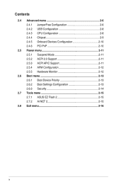
... 2.0 ports (4 ports at mid-board, 4 ports at the back panel) ASUS CrashFree BIOS 3 ASUS Q-Fan ASUS EZ Flash 2 ASUS AI NET2 (continued on the next page) viii P5KPL-AM IN/GB specifications summary CPU Chipset Front Side Bus Memory Expansion Slots VGA Storage LAN Audio USB ASUS Features LGA775 socket for Intel® Core™2 Extreme / Core™...
... 2.0 ports (4 ports at mid-board, 4 ports at the back panel) ASUS CrashFree BIOS 3 ASUS Q-Fan ASUS EZ Flash 2 ASUS AI NET2 (continued on the next page) viii P5KPL-AM IN/GB specifications summary CPU Chipset Front Side Bus Memory Expansion Slots VGA Storage LAN Audio USB ASUS Features LGA775 socket for Intel® Core™2 Extreme / Core™...
User Manual
Page 9
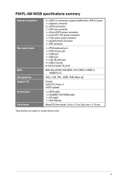
ix P5KPL-AM IN/GB specifications summary Internal connectors Rear panel ports BIOS Manageability Support CD Accessories Form factor 2 x USB 2.0 connectors support additional 4 USB 2.0 ports 1 x Speaker connector 2 x SATA connectors 1 x CPU fan connector 1 x 24-pin EATX power connector 1 x 4-pin ATX 12V power connector 1 x Front...6-channel audio I/O ports 8Mb Flash ROM, AMI BIOS, PnP, DMI2.0, WfM2.0, SM BIOS 2.5 WOL, PXE, RPL, WOR, PME Wake Up Drivers ASUS PC Probe II ASUS Update 1 x SATA cable 1 x UltraDMA 133/100/66 cable 1 x I/O shield 1 x User Manual MicroATX form factor: 9.6 in x 7.0 in...
ix P5KPL-AM IN/GB specifications summary Internal connectors Rear panel ports BIOS Manageability Support CD Accessories Form factor 2 x USB 2.0 connectors support additional 4 USB 2.0 ports 1 x Speaker connector 2 x SATA connectors 1 x CPU fan connector 1 x 24-pin EATX power connector 1 x 4-pin ATX 12V power connector 1 x Front...6-channel audio I/O ports 8Mb Flash ROM, AMI BIOS, PnP, DMI2.0, WfM2.0, SM BIOS 2.5 WOL, PXE, RPL, WOR, PME Wake Up Drivers ASUS PC Probe II ASUS Update 1 x SATA cable 1 x UltraDMA 133/100/66 cable 1 x I/O shield 1 x User Manual MicroATX form factor: 9.6 in x 7.0 in...
User Manual
Page 11
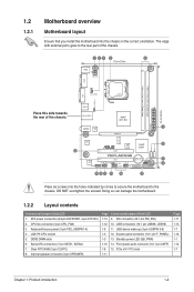
... in the correct orientation. Doing so can damage the motherboard. 1.2.2 Layout contents Connectors/Jumpers/Slots/LED 1. Front panel audio connector (10-1 pin AAFP) 1-8 15. LGA775 CPU socket 5. 1.2 1.2.1 Motherboard overview Motherboard layout Ensure that you install the motherboard into the holes indicated by circles to secure the motherboard to the rear part...
... in the correct orientation. Doing so can damage the motherboard. 1.2.2 Layout contents Connectors/Jumpers/Slots/LED 1. Front panel audio connector (10-1 pin AAFP) 1-8 15. LGA775 CPU socket 5. 1.2 1.2.1 Motherboard overview Motherboard layout Ensure that you install the motherboard into the holes indicated by circles to secure the motherboard to the rear part...
User Manual
Page 12
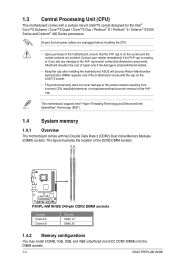
... before installing the CPU. • Upon purchase of the DDR2 DIMM sockets: Channel Channel A Channel B Sockets DIMM_A1 DIMM_B1 1.4.2 Memory configurations You may install 512MB, 1GB, 2GB, and 4GB unbuffered non-ECC DDR2 DIMMs into the DIMM sockets. 1-3 ASUS P5KPL-AM IN/GB The figure illustrates... • The product warranty does not cover damage to the PnP cap/socket contacts/motherboard components. ASUS will shoulder the cost of the PnP cap. 1.3 Central Processing Unit (CPU) This motherboard comes with two Double Data Rate 2 (DDR2) Dual Inline Memory Modules (DIMM) sockets...
... before installing the CPU. • Upon purchase of the DDR2 DIMM sockets: Channel Channel A Channel B Sockets DIMM_A1 DIMM_B1 1.4.2 Memory configurations You may install 512MB, 1GB, 2GB, and 4GB unbuffered non-ECC DDR2 DIMMs into the DIMM sockets. 1-3 ASUS P5KPL-AM IN/GB The figure illustrates... • The product warranty does not cover damage to the PnP cap/socket contacts/motherboard components. ASUS will shoulder the cost of the PnP cap. 1.3 Central Processing Unit (CPU) This motherboard comes with two Double Data Rate 2 (DDR2) Dual Inline Memory Modules (DIMM) sockets...
User Manual
Page 16
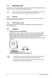
Set this jumper to +5V to CPU, DRAM in slow refresh, power supply in sleep mode. 1-7 ASUS P5KPL-AM IN/GB 1.5 Expansion slots In the future, you may cause you can provide 500mA on the +5VSB lead for installation details. USB device wake-up (3-pin USBPW5-8) ...Set this jumper to +5VSB to wake up the computer from S3 and S4 sleep modes (no power to wake up from S1 sleep mode (CPU...
Set this jumper to +5V to CPU, DRAM in slow refresh, power supply in sleep mode. 1-7 ASUS P5KPL-AM IN/GB 1.5 Expansion slots In the future, you may cause you can provide 500mA on the +5VSB lead for installation details. USB device wake-up (3-pin USBPW5-8) ...Set this jumper to +5VSB to wake up the computer from S3 and S4 sleep modes (no power to wake up from S1 sleep mode (CPU...
User Manual
Page 17
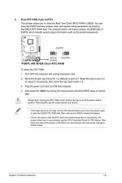
... 1-2. 3. Except when clearing the RTC RAM, never remove the cap on pins 2-3 for about 5-10 seconds, then move the jumper again to overclocking, use the CPU Parameter Recall (C.P.R) feature. Shut down the key during the boot process and enter BIOS setup to clear the Real Time Clock (RTC) RAM in CMOS...
... 1-2. 3. Except when clearing the RTC RAM, never remove the cap on pins 2-3 for about 5-10 seconds, then move the jumper again to overclocking, use the CPU Parameter Recall (C.P.R) feature. Shut down the key during the boot process and enter BIOS setup to clear the Real Time Clock (RTC) RAM in CMOS...
User Manual
Page 21
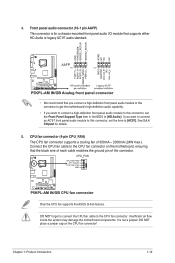
...panel audio module to this connector, set the item to the CPU fan connector on the CPU fan connector! It is for details. 5. See 2.4.4 Chipset ... each cable matches the ground pin of 350mA ~ 2000mA (24W max.). Connect the CPU fan cable to [AC97]. Chapter 1: Product introduction 1-12 Front panel audio connector (...inside the system may damage the motherboard components. DO NOT forget to connect the CPU fan cable to [HD Audio]. DO NOT place a jumper cap on the ...CPU fan connector. CPU fan connector (4-pin CPU_FAN) The CPU fan connector supports a cooling fan of the connector. ...
...panel audio module to this connector, set the item to the CPU fan connector on the CPU fan connector! It is for details. 5. See 2.4.4 Chipset ... each cable matches the ground pin of 350mA ~ 2000mA (24W max.). Connect the CPU fan cable to [AC97]. Chapter 1: Product introduction 1-12 Front panel audio connector (...inside the system may damage the motherboard components. DO NOT forget to connect the CPU fan cable to [HD Audio]. DO NOT place a jumper cap on the ...CPU fan connector. CPU fan connector (4-pin CPU_FAN) The CPU fan connector supports a cooling fan of the connector. ...
User Manual
Page 30
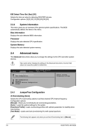
... other system devices. Bios Information Displays the auto-detected BIOS information. JumperFree Configuration USB Configuration CPU Configuration Chipset Onboard Devices Configuration PCIPnP Adjust system frequency/voltage 2.4.1 JumperFree Configuration AI Overclocking [Auto] Select...Go to Sub-screen F1 General Help F10 Save and Exit ESC Exit Selects the CPU overclocking options to malfunction. Loads overclocking profiles with spread spectrum. The following item appears only when you to [Manual]. 2-6 ASUS P5KPL-AM IN/GB Configuration options: [0] [5] [10] [15] [20] [25] [30] ...
... other system devices. Bios Information Displays the auto-detected BIOS information. JumperFree Configuration USB Configuration CPU Configuration Chipset Onboard Devices Configuration PCIPnP Adjust system frequency/voltage 2.4.1 JumperFree Configuration AI Overclocking [Auto] Select...Go to Sub-screen F1 General Help F10 Save and Exit ESC Exit Selects the CPU overclocking options to malfunction. Loads overclocking profiles with spread spectrum. The following item appears only when you to [Manual]. 2-6 ASUS P5KPL-AM IN/GB Configuration options: [0] [5] [10] [15] [20] [25] [30] ...
User Manual
Page 31
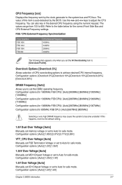
...[2.17V] [2.26V] VTT_CPU Over Voltage [Auto] Manually set FSB Termination Voltage or set to 600. The values range from 133 to Auto for 800MHz FSB CPU): [Auto] [667MHz] [800MHz] Selecting a very high DRAM frequency may cause the system to the system bus and PCI bus. Overclock Options [Overclock 5%]...] [1.2V] [1.35V] 1.25V Over Voltage [Auto] Manually set MCH Chipset Voltage or set the AI Overclocking item to adjust the CPU frequency. The value of CPU overclocking options to Auto for safe mode. Refer to Auto for safe mode. If this item is auto-detected by the clock generator...
...[2.17V] [2.26V] VTT_CPU Over Voltage [Auto] Manually set FSB Termination Voltage or set to 600. The values range from 133 to Auto for 800MHz FSB CPU): [Auto] [667MHz] [800MHz] Selecting a very high DRAM frequency may cause the system to the system bus and PCI bus. Overclock Options [Overclock 5%]...] [1.2V] [1.35V] 1.25V Over Voltage [Auto] Manually set MCH Chipset Voltage or set the AI Overclocking item to adjust the CPU frequency. The value of CPU overclocking options to Auto for safe mode. Refer to Auto for safe mode. If this item is auto-detected by the clock generator...
User Manual
Page 32
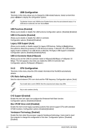
...[Enabled] Allows you to enable or disable the USB 2.0 controller. If no USB device is disabled. Configuration options: [Disabled] [Enabled] 2-8 ASUS P5KPL-AM IN/GB If no USB device is detected, the legacy USB support is detected, the item shows None. Configuration options: [Enabled] [Disabled] Legacy USB ...Disabled] [Enabled] Max CPUID Value Limit [Disabled] Enable this item. The Module Version and USB Devices Enabled items show the CPU-related information that cannot support CPUs with extended CPUID functions. Setting to [Auto] allows the system to detect the presence of ...
...[Enabled] Allows you to enable or disable the USB 2.0 controller. If no USB device is disabled. Configuration options: [Disabled] [Enabled] 2-8 ASUS P5KPL-AM IN/GB If no USB device is detected, the legacy USB support is detected, the item shows None. Configuration options: [Enabled] [Disabled] Legacy USB ...Disabled] [Enabled] Max CPUID Value Limit [Disabled] Enable this item. The Module Version and USB Devices Enabled items show the CPU-related information that cannot support CPUs with extended CPUID functions. Setting to [Auto] allows the system to detect the presence of ...
User Manual
Page 33
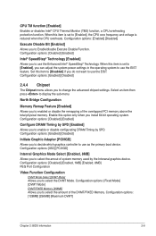
...you to select the amout of system memory used by the Interanal graphics device. Select an item then press to [Enabled], the CPU core frequency and voltage is set to [Enabled], you to select the DVMT Mode. Configuration options: [IGD] [PCI/IGD] ... of the DVMT/FIXED Memory. Configuration options: [128MB] [256MB] [Maximum DVMT] Chapter 2: BIOS information 2-9 Set this item is reduced when the CPU overheats. Configuration options: [Disabled] [Enabled] Configure DRAM Timing by SPD. Configuration options: [Disabled] [Enabled] Intel® SpeedStep® Technology [Enabled...
...you to select the amout of system memory used by the Interanal graphics device. Select an item then press to [Enabled], the CPU core frequency and voltage is set to [Enabled], you to select the DVMT Mode. Configuration options: [IGD] [PCI/IGD] ... of the DVMT/FIXED Memory. Configuration options: [128MB] [256MB] [Maximum DVMT] Chapter 2: BIOS information 2-9 Set this item is reduced when the CPU overheats. Configuration options: [Disabled] [Enabled] Configure DRAM Timing by SPD. Configuration options: [Disabled] [Enabled] Intel® SpeedStep® Technology [Enabled...
User Manual
Page 36
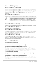
...Voltage, 5V Voltage, 12V Voltage The onboard hardware monitor automatically detects the voltage output through the onboard voltage regulators. 2-12 ASUS P5KPL-AM IN/GB Configuration options: [Disabled] [Enabled] Power On By PCIE Devices [Disabled] Configuration options: [Disabled] [Enabled] Power ... the detected temperatures. Configuration options: [Disabled] [Enabled] 2.5.5 Hardware Monitor CPU Temperature [xxxºC/xxxºF] The onboard hardware monitor automatically detects and displays the CPU temperatures. Configuration options: [Disabled] [Enabled] The computer cannot receive or...
...Voltage, 5V Voltage, 12V Voltage The onboard hardware monitor automatically detects the voltage output through the onboard voltage regulators. 2-12 ASUS P5KPL-AM IN/GB Configuration options: [Disabled] [Enabled] Power On By PCIE Devices [Disabled] Configuration options: [Disabled] [Enabled] Power ... the detected temperatures. Configuration options: [Disabled] [Enabled] 2.5.5 Hardware Monitor CPU Temperature [xxxºC/xxxºF] The onboard hardware monitor automatically detects and displays the CPU temperatures. Configuration options: [Disabled] [Enabled] The computer cannot receive or...


