User Manual
Page 3
... Processing Unit (CPU 1-3 1.4 System memory 1-3 1.4.1 Overview 1-3 1.4.2 Memory configurations 1-3 1.5 Expansion slots 1-7 1.5.1 PCI slots 1-7 1.5.2 PCI Express x16 slot 1-7 1.6 Jumpers 1-7 1.7 Connectors 1-9 1.7.1 Rear panel ports 1-9 1.7.2 Internal connectors 1-10 1.8 Software support 1-15 1.8.1 Installing an operating system 1-15 1.8.2 Support CD information 1-15 Chapter 2: BIOS information 2.1 Managing and updating your BIOS 2-1 2.1.1 ASUS Update utility 2-1 2.1.2 ASUS EZ Flash 2 utility 2-2 2.1.3 ASUS CrashFree BIOS 3 utility 2-3 2.2 BIOS setup program 2-4 2.3 Main menu...
... Processing Unit (CPU 1-3 1.4 System memory 1-3 1.4.1 Overview 1-3 1.4.2 Memory configurations 1-3 1.5 Expansion slots 1-7 1.5.1 PCI slots 1-7 1.5.2 PCI Express x16 slot 1-7 1.6 Jumpers 1-7 1.7 Connectors 1-9 1.7.1 Rear panel ports 1-9 1.7.2 Internal connectors 1-10 1.8 Software support 1-15 1.8.1 Installing an operating system 1-15 1.8.2 Support CD information 1-15 Chapter 2: BIOS information 2.1 Managing and updating your BIOS 2-1 2.1.1 ASUS Update utility 2-1 2.1.2 ASUS EZ Flash 2 utility 2-2 2.1.3 ASUS CrashFree BIOS 3 utility 2-3 2.2 BIOS setup program 2-4 2.3 Main menu...
User Manual
Page 8
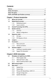
...66 connector - 2 x SATA 3Gb/s connectors Gb LAN VT1705 6-channel High Definition Audio CODEC 8 x USB 2.0 ports (4 ports at mid-board, 4 ports at the back panel) ASUS CrashFree BIOS 3 ASUS Q-Fan ASUS EZ Flash 2 ASUS AI NET2 (continued on the next page) viii P5KPL-AM IN/GB specifications summary CPU Chipset Front Side Bus Memory Expansion Slots VGA Storage LAN Audio USB ASUS Features LGA775 socket for Intel® Core™2 Extreme / Core™2 Quad / Core™2 Duo / Pentium® D / Pentium® 4 / Celeron® E1000 Series and Celeron® 400 Series processors Supports Intel...
...66 connector - 2 x SATA 3Gb/s connectors Gb LAN VT1705 6-channel High Definition Audio CODEC 8 x USB 2.0 ports (4 ports at mid-board, 4 ports at the back panel) ASUS CrashFree BIOS 3 ASUS Q-Fan ASUS EZ Flash 2 ASUS AI NET2 (continued on the next page) viii P5KPL-AM IN/GB specifications summary CPU Chipset Front Side Bus Memory Expansion Slots VGA Storage LAN Audio USB ASUS Features LGA775 socket for Intel® Core™2 Extreme / Core™2 Quad / Core™2 Duo / Pentium® D / Pentium® 4 / Celeron® E1000 Series and Celeron® 400 Series processors Supports Intel...
User Manual
Page 9
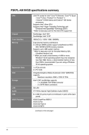
... Internal connectors Rear panel ports BIOS Manageability Support CD Accessories Form factor 2 x USB 2.0 connectors support additional 4 USB 2.0 ports 1 x Speaker connector 2 x SATA connectors 1 x CPU fan connector 1 x 24-pin EATX power connector 1 x 4-pin ATX 12V power connector 1 x Front panel audio connector 1 x System Panel connector 1 x IDE connector 1 x PS/2 keyboard port 1 x PS/2 mouse port 1 x COM port 1 x VGA port 1 x LAN (RJ-45) port 4 x USB 2.0 ports 6-channel audio I/O ports 8Mb Flash ROM, AMI BIOS, PnP, DMI2.0, WfM2.0, SM BIOS 2.5 WOL, PXE, RPL, WOR, PME Wake Up Drivers ASUS...
... Internal connectors Rear panel ports BIOS Manageability Support CD Accessories Form factor 2 x USB 2.0 connectors support additional 4 USB 2.0 ports 1 x Speaker connector 2 x SATA connectors 1 x CPU fan connector 1 x 24-pin EATX power connector 1 x 4-pin ATX 12V power connector 1 x Front panel audio connector 1 x System Panel connector 1 x IDE connector 1 x PS/2 keyboard port 1 x PS/2 mouse port 1 x COM port 1 x VGA port 1 x LAN (RJ-45) port 4 x USB 2.0 ports 6-channel audio I/O ports 8Mb Flash ROM, AMI BIOS, PnP, DMI2.0, WfM2.0, SM BIOS 2.5 WOL, PXE, RPL, WOR, PME Wake Up Drivers ASUS...
User Manual
Page 11
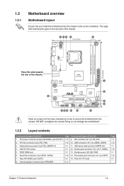
...14. Front panel audio connector (10-1 pin AAFP) 1-8 15. Doing so can damage the motherboard. 1.2.2 Layout contents Connectors/Jumpers/Slots/LED 1. System panel connector (10-1 pin F_PANEL) 1-3 13. Place six screws into the chassis in the correct orientation. Keyboard/mouse power (3-pin PS2_USBPW1-4) 4. Serial ATA connectors (7-pin SATA1, SATA2) 7. USB connectors (10-1 pin USB56, USB78) 1-9 11. DO NOT overtighten the screws! USB device wake-up (3-pin USBPW 5-8) 1-3 12. CPU fan connector (4-pin CPU_FAN) 3. Clear RTC RAM (3-pin CLRTC) 8. PCIe x16 / PCI slots 1-11 Page...
...14. Front panel audio connector (10-1 pin AAFP) 1-8 15. Doing so can damage the motherboard. 1.2.2 Layout contents Connectors/Jumpers/Slots/LED 1. System panel connector (10-1 pin F_PANEL) 1-3 13. Place six screws into the chassis in the correct orientation. Keyboard/mouse power (3-pin PS2_USBPW1-4) 4. Serial ATA connectors (7-pin SATA1, SATA2) 7. USB connectors (10-1 pin USB56, USB78) 1-9 11. DO NOT overtighten the screws! USB device wake-up (3-pin USBPW 5-8) 1-3 12. CPU fan connector (4-pin CPU_FAN) 3. Clear RTC RAM (3-pin CLRTC) 8. PCIe x16 / PCI slots 1-11 Page...
User Manual
Page 16
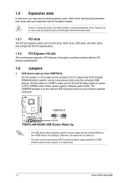
... the PCI specifications. 1.5.2 PCI Express x16 slot This motherboard supports a PCI Express x16 graphics card that you may need to the technical documentation that comes with the PCI Express specifications. 1.6 Jumpers 1. Failure to unplug the power cord before adding or removing expansion cards. Otherwise, the system will not power up the computer from S3 and S4 sleep modes (no power to CPU, DRAM in slow refresh, power supply in sleep mode. 1-7 ASUS P5KPL-AM IN/GB The USBPW5-8 jumper is for the internal USB connectors that...
... the PCI specifications. 1.5.2 PCI Express x16 slot This motherboard supports a PCI Express x16 graphics card that you may need to the technical documentation that comes with the PCI Express specifications. 1.6 Jumpers 1. Failure to unplug the power cord before adding or removing expansion cards. Otherwise, the system will not power up the computer from S3 and S4 sleep modes (no power to CPU, DRAM in slow refresh, power supply in sleep mode. 1-7 ASUS P5KPL-AM IN/GB The USBPW5-8 jumper is for the internal USB connectors that...
User Manual
Page 18
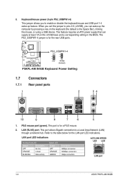
... port allows Gigabit connection to enable or disable the keyboard/mouse and USB port 1-4 wake-up the computer by pressing a key on the +5VSB lead, and a corresponding setting in the BIOS. This feature requires an ATX power supply that can wake up feature. Keyboard/mouse power (3-pin PS2_USBPW1-4) This jumper allows you can supply at least 1A on the keyboard (the default is the Space Bar), clicking the mouse, or using a USB device. LAN (RJ-45) port...
... port allows Gigabit connection to enable or disable the keyboard/mouse and USB port 1-4 wake-up the computer by pressing a key on the +5VSB lead, and a corresponding setting in the BIOS. This feature requires an ATX power supply that can wake up feature. Keyboard/mouse power (3-pin PS2_USBPW1-4) This jumper allows you can supply at least 1A on the keyboard (the default is the Space Bar), clicking the mouse, or using a USB device. LAN (RJ-45) port...
User Manual
Page 20
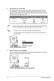
... removed to configure your device. The speaker allows you connect the IDE cable. • Use the 80-conductor IDE cable for Ultra DMA 133/100/66 IDE devices. • If any device jumper is for the chassis-mounted system warning speaker. 2. This prevents incorrect insertion when you to Cable-Select, ensure that all other device jumpers have the same setting. 3. IDE connector (40-1 pin PRI_IDE) The onboard IDE connector is set to hear system beeps and warnings. 1-11 ASUS P5KPL...
... removed to configure your device. The speaker allows you connect the IDE cable. • Use the 80-conductor IDE cable for Ultra DMA 133/100/66 IDE devices. • If any device jumper is for the chassis-mounted system warning speaker. 2. This prevents incorrect insertion when you to Cable-Select, ensure that all other device jumpers have the same setting. 3. IDE connector (40-1 pin PRI_IDE) The onboard IDE connector is set to hear system beeps and warnings. 1-11 ASUS P5KPL...
User Manual
Page 24
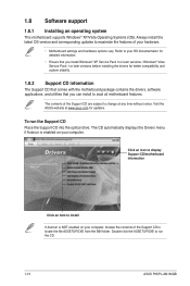
... can install to change at www.asus.com for updates. 1.8 Software support 1.8.1 Installing an operating system This motherboard supports Windows® XP/Vista Operating Systems (OS). Refer to your computer. To run the CD. 1-15 ASUS P5KPL-AM IN/GB The contents of the Support CD to run the Support CD Place the Support CD into the optical drive. Double-click the ASSETUP.EXE to locate the file ASSETUP...
... can install to change at www.asus.com for updates. 1.8 Software support 1.8.1 Installing an operating system This motherboard supports Windows® XP/Vista Operating Systems (OS). Refer to your computer. To run the CD. 1-15 ASUS P5KPL-AM IN/GB The contents of the Support CD to run the Support CD Place the Support CD into the optical drive. Double-click the ASSETUP.EXE to locate the file ASSETUP...
User Manual
Page 25
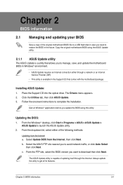
... a network or an Internet Service Provider (ISP). • This utility is a utility that comes with the motherboard package. Chapter 2 BIOS information 2.1 Managing and updating your BIOS Save a copy of the original motherboard BIOS file to a USB flash disk in case you need to download then click Next. Installing ASUS Update: 1. b. Chapter 2: BIOS information 2-1 The Drivers menu appears. 2. From the FTP site, select the BIOS version you update the BIOS using the ASUS Update utility.. 2.1.1 ASUS Update utility The ASUS Update is available in the Support CD...
... a network or an Internet Service Provider (ISP). • This utility is a utility that comes with the motherboard package. Chapter 2 BIOS information 2.1 Managing and updating your BIOS Save a copy of the original motherboard BIOS file to a USB flash disk in case you need to download then click Next. Installing ASUS Update: 1. b. Chapter 2: BIOS information 2-1 The Drivers menu appears. 2. From the FTP site, select the BIOS version you update the BIOS using the ASUS Update utility.. 2.1.1 ASUS Update utility The ASUS Update is available in the Support CD...
User Manual
Page 26
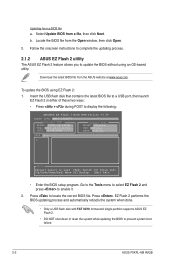
... Flash 2 BIOS ROM Utility V3.34 FLASH TYPE: MXIC 25L8005 Current ROM BOARD: P5KPL-AM IN/GB VER: 0303 (H:00 B:03) DATE: 02/09/2009 Update ROM BOARD: Unknown VER: Unknown DATE: Unknown PATH: A:\ A: Note [Enter] Select or Load [Tab] Switch [V] Drive Info [Up/Down/Home/End] Move [B] Backup [Esc] Exit • Enter the BIOS setup program. Updating from a file, then click Next. Select Update BIOS from a BIOS file a. Press to prevent system boot failure. 2-2 ASUS P5KPL-AM IN/GB EZ Flash...
... Flash 2 BIOS ROM Utility V3.34 FLASH TYPE: MXIC 25L8005 Current ROM BOARD: P5KPL-AM IN/GB VER: 0303 (H:00 B:03) DATE: 02/09/2009 Update ROM BOARD: Unknown VER: Unknown DATE: Unknown PATH: A:\ A: Note [Enter] Select or Load [Tab] Switch [V] Drive Info [Up/Down/Home/End] Move [B] Backup [Esc] Exit • Enter the BIOS setup program. Updating from a file, then click Next. Select Update BIOS from a BIOS file a. Press to prevent system boot failure. 2-2 ASUS P5KPL-AM IN/GB EZ Flash...
User Manual
Page 28
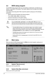
... off then back on. Select the Load Setup Defaults item under the Exit menu. We recommend that you always shut down procedure. • Press ++ simultaneously. • Press the reset button on the system chassis. • Press the power button to enter Setup after changing any of the following procedures: • Restart using this motherboard. 2.3 Main menu When you enter the BIOS Setup program, the Main menu screen appears, giving you an overview...
... off then back on. Select the Load Setup Defaults item under the Exit menu. We recommend that you always shut down procedure. • Press ++ simultaneously. • Press the reset button on the system chassis. • Press the power button to enter Setup after changing any of the following procedures: • Restart using this motherboard. 2.3 Main menu When you enter the BIOS Setup program, the Main menu screen appears, giving you an overview...
User Manual
Page 29
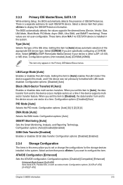
... options: [Disabled] [Auto] PIO Mode [Auto] Selects the PIO mode. Type [Auto] Selects the type of IDE/SATA devices. ATA/IDE Configuration [Enhanced] Sets the ATA/IDE configuration. Configuration options: [Disabled] [Compatible] [Enhanced] Enhanced Mode Support On [S-ATA] Sets Serial ATA, Parallel ATA, or both as native mode. Configuration options: [Auto] [Disabled] [Enabled] 32Bit Data Transfer [Enabled] Enables or disables 32-bit data transfer. 2.3.3 Primary IDE Master/Slave, SATA 1/2 While entering Setup, the BIOS automatically detects the presence of the IDE drive. Setting...
... options: [Disabled] [Auto] PIO Mode [Auto] Selects the PIO mode. Type [Auto] Selects the type of IDE/SATA devices. ATA/IDE Configuration [Enhanced] Sets the ATA/IDE configuration. Configuration options: [Disabled] [Compatible] [Enhanced] Enhanced Mode Support On [S-ATA] Sets Serial ATA, Parallel ATA, or both as native mode. Configuration options: [Auto] [Disabled] [Enabled] 32Bit Data Transfer [Enabled] Enables or disables 32-bit data transfer. 2.3.3 Primary IDE Master/Slave, SATA 1/2 While entering Setup, the BIOS automatically detects the presence of the IDE drive. Setting...
User Manual
Page 30
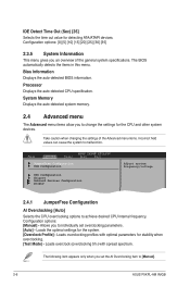
... automatically detects the items in this menu. Bios Information Displays the auto-detected BIOS information. Loads overclocking profiles with spread spectrum. JumperFree Configuration USB Configuration CPU Configuration Chipset Onboard Devices Configuration PCIPnP Adjust system frequency/voltage 2.4.1 JumperFree Configuration AI Overclocking [Auto] Select Screen Select Item Enter Go to Sub-screen F1 General Help F10 Save and Exit ESC Exit Selects the CPU overclocking options to change the settings for detecting ATA/ATAPI devices. IDE Detect Time Out (Sec) [35] Selects...
... automatically detects the items in this menu. Bios Information Displays the auto-detected BIOS information. Loads overclocking profiles with spread spectrum. JumperFree Configuration USB Configuration CPU Configuration Chipset Onboard Devices Configuration PCIPnP Adjust system frequency/voltage 2.4.1 JumperFree Configuration AI Overclocking [Auto] Select Screen Select Item Enter Go to Sub-screen F1 General Help F10 Save and Exit ESC Exit Selects the CPU overclocking options to change the settings for detecting ATA/ATAPI devices. IDE Detect Time Out (Sec) [35] Selects...
User Manual
Page 32
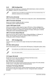
... Setting [Auto] Sets the ration between CPU core clock and the FSB frequency. Key in CMOS, then the actual and set the USB 2.0 controller mode to HiSpeed (480 Mbps) or FullSpeed (12 Mbps). C1E Support [Enabled] Enable this item when the processor supports Vanderpool technology. Configuration options: [Disabled] [Enabled] 2-8 ASUS P5KPL-AM IN/GB Setting to [Auto] allows the system to detect the presence of this item. This item appears only when you to set values may differ. Configuration options: [Disabled] [Enabled] Vanderpool Technology [Enabled] Enable...
... Setting [Auto] Sets the ration between CPU core clock and the FSB frequency. Key in CMOS, then the actual and set the USB 2.0 controller mode to HiSpeed (480 Mbps) or FullSpeed (12 Mbps). C1E Support [Enabled] Enable this item when the processor supports Vanderpool technology. Configuration options: [Disabled] [Enabled] 2-8 ASUS P5KPL-AM IN/GB Setting to [Auto] allows the system to detect the presence of this item. This item appears only when you to set values may differ. Configuration options: [Disabled] [Enabled] Vanderpool Technology [Enabled] Enable...
User Manual
Page 33
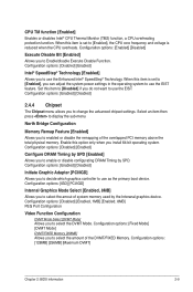
... 1MB] [Enabled, 8MB] PEG Port Configuration Video Function Configuration DVMT Mode Select [DVMT Mode] Allows you to use the Enhanced Intel® SpeedStep® Technology. Set this item is set to [Enabled], the CPU core frequency and voltage is set to [Enabled], you to decide which graphics controller to Enable/disable Execute Disable Function. CPU TM function [Enabled] Enables or disables Intel® CPU Thermal Monitor (TM2) function, a CPU overheating protection function. Configuration options: [IGD] [PCI/IGD] Internal Graphics Mode Select [Enabled, 8MB] Allows you install 64-bit...
... 1MB] [Enabled, 8MB] PEG Port Configuration Video Function Configuration DVMT Mode Select [DVMT Mode] Allows you to use the Enhanced Intel® SpeedStep® Technology. Set this item is set to [Enabled], the CPU core frequency and voltage is set to [Enabled], you to decide which graphics controller to Enable/disable Execute Disable Function. CPU TM function [Enabled] Enables or disables Intel® CPU Thermal Monitor (TM2) function, a CPU overheating protection function. Configuration options: [IGD] [PCI/IGD] Internal Graphics Mode Select [Enabled, 8MB] Allows you install 64-bit...
User Manual
Page 34
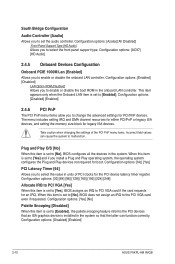
...Onboard PCIE 1000M Lan [Enabled] Allows you install a Plug and Play operating system, the operating system configures the Plug and Play devices not required for boot. Configuration options: [Azalia] [All Disabled] Front Panel Support Type [HD Audio] Allows you to select the front panel support type. Take caution when changing the settings of PCI clocks for PCI/PnP devices. Configuration options: [Enabled] [Disabled] LAN Option ROM [Disabled] Allows you to enable or disable the boot ROM in the system. Configuration options: [Disabled] [Enabled] 2-10 ASUS P5KPL-AM IN/GB...
...Onboard PCIE 1000M Lan [Enabled] Allows you install a Plug and Play operating system, the operating system configures the Plug and Play devices not required for boot. Configuration options: [Azalia] [All Disabled] Front Panel Support Type [HD Audio] Allows you to select the front panel support type. Take caution when changing the settings of PCI clocks for PCI/PnP devices. Configuration options: [Enabled] [Disabled] LAN Option ROM [Disabled] Allows you to enable or disable the boot ROM in the system. Configuration options: [Disabled] [Enabled] 2-10 ASUS P5KPL-AM IN/GB...

User Manual
Page 35
...). Configuration options: [S1 (POS) Only] [S3 Only] [Auto] [S1(POS) Only] - In S1 sleep state, the system appears suspended and stays in the S1 state. Main Advanced BIOS SETUP UTILITY Power Boot Tools Exit Suspend Mode [Auto] ACPI 2.0 Support [Disabled] ACPI APIC Support [Enabled] APM Configuration Hardware Monitor Select the ACPI state used for system suspend. IRQ-xx assigned to [PCI Device] When set to [Reserved], the IRQ is reserved for legacy ISA devices. Enables the system to enter...
...). Configuration options: [S1 (POS) Only] [S3 Only] [Auto] [S1(POS) Only] - In S1 sleep state, the system appears suspended and stays in the S1 state. Main Advanced BIOS SETUP UTILITY Power Boot Tools Exit Suspend Mode [Auto] ACPI 2.0 Support [Disabled] ACPI APIC Support [Enabled] APM Configuration Hardware Monitor Select the ACPI state used for system suspend. IRQ-xx assigned to [PCI Device] When set to [Reserved], the IRQ is reserved for legacy ISA devices. Enables the system to enter...
User Manual
Page 36
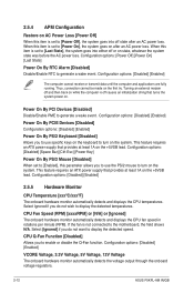
... +5VSB lead. Configuration options: [Power Off] [Power On] [Last State] Power On By RTC Alarm [Disabled] Disable/Enable RTC to the motherboard, the field shows N/A. Select Ignored if you do not wish to display the detected speed. When this item is set to turn on after an AC power loss. Configuration options: [Disabled] [Enabled] Power On By PCIE Devices [Disabled] Configuration options: [Disabled] [Enabled] Power On By PS/2 Keyboard [Disabled] Allows you to use specific keys on the keyboard to [Power Off], the system...
... +5VSB lead. Configuration options: [Power Off] [Power On] [Last State] Power On By RTC Alarm [Disabled] Disable/Enable RTC to the motherboard, the field shows N/A. Select Ignored if you do not wish to display the detected speed. When this item is set to turn on after an AC power loss. Configuration options: [Disabled] [Enabled] Power On By PCIE Devices [Disabled] Configuration options: [Disabled] [Enabled] Power On By PS/2 Keyboard [Disabled] Allows you to use specific keys on the keyboard to [Power Off], the system...
User Manual
Page 37
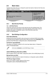
...screen depends on self tests (POST) while booting to decrease the time needed to boot the system. Configuration options: [Disabled] [Enabled] [Auto] Chapter 2: BIOS information 2-13 Configuration options: [Hard Drive] [Removable Dev.] [ATAPI CD-ROM] [Disabled] 2.6.2 Boot Settings Configuration Quick Boot [Enabled] Enabling this item to [Enabled] to display the submenu. Select an item then press to use the ASUS MyLogo™ feature. Configuration options: [Force BIOS] [Keep Current] Bootup Num-Lock [On] Allows you to enable or disable support for option ROM. Boot Settings...
...screen depends on self tests (POST) while booting to decrease the time needed to boot the system. Configuration options: [Disabled] [Enabled] [Auto] Chapter 2: BIOS information 2-13 Configuration options: [Hard Drive] [Removable Dev.] [ATAPI CD-ROM] [Disabled] 2.6.2 Boot Settings Configuration Quick Boot [Enabled] Enabling this item to [Enabled] to display the submenu. Select an item then press to use the ASUS MyLogo™ feature. Configuration options: [Force BIOS] [Keep Current] Bootup Num-Lock [On] Allows you to enable or disable support for option ROM. Boot Settings...
User Manual
Page 39
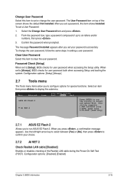
... Realtek LAN cable [Disabled] Enables or disables checking of the Realtek LAN cable during the Power-On Self‑Test (POST). To change the user password. Main Advanced Power BIOS SETUP UTILITY Boot Tools Exit ASUS EZ Flash 2 AI NET 2 Press ENTER to run ASUS EZ Flash 2. Select the Change User Password item and press . 2. Select an item then press to select and update BIOS. From the password box, type a password composed of the screen shows the default Not Installed. Password Check [Setup] When set to [Setup], BIOS checks...
... Realtek LAN cable [Disabled] Enables or disables checking of the Realtek LAN cable during the Power-On Self‑Test (POST). To change the user password. Main Advanced Power BIOS SETUP UTILITY Boot Tools Exit ASUS EZ Flash 2 AI NET 2 Press ENTER to run ASUS EZ Flash 2. Select the Change User Password item and press . 2. Select an item then press to select and update BIOS. From the password box, type a password composed of the screen shows the default Not Installed. Password Check [Setup] When set to [Setup], BIOS checks...


