
User Manual
Page 31
All rights reserved. done Write to file...... Version 1.19(ASUS V2.07(03.11.24BB)) Copyright (C) 2002 American Megatrends, Inc. ok A:\> 當 BIOS DOS 31 Reading flash ..... BIOS 2.1 使用 AFUDOS BIOS AFUDOS DOS BIOS BIOS 程式。AFUDOS BIOS BIOS BIOS 程式 BIOS 程式。 1.2MB BIOS 1 AFUDOS 程式(afudos. exe 2 DOS afudos /o[filename filename A:\>afudos /oOLDBIOS1.rom 3. 按下 afudos /oOLDBIOS1.rom AMI Firmware Update Utility -
All rights reserved. done Write to file...... Version 1.19(ASUS V2.07(03.11.24BB)) Copyright (C) 2002 American Megatrends, Inc. ok A:\> 當 BIOS DOS 31 Reading flash ..... BIOS 2.1 使用 AFUDOS BIOS AFUDOS DOS BIOS BIOS 程式。AFUDOS BIOS BIOS BIOS 程式 BIOS 程式。 1.2MB BIOS 1 AFUDOS 程式(afudos. exe 2 DOS afudos /o[filename filename A:\>afudos /oOLDBIOS1.rom 3. 按下 afudos /oOLDBIOS1.rom AMI Firmware Update Utility -

User Manual
Page 32
... Firmware Update Utility - done Please restart your computer A:\> 32 BIOS Version 1.19(ASUS V2.07(03.11.24BB)) Copyright (C) 2002 American Megatrends, Inc. 更新 BIOS 程式 AFUDOS BIOS 程式。 1 tw.asus.com BIOS 片中。 BIOS BIOS 2. 將 AFUDOS.EXE BIOS 3 DOS afudos /i[filename filename BIOS 程式。 A:\>afudos /iP5B-VM DO.ROM 4. Version...
... Firmware Update Utility - done Please restart your computer A:\> 32 BIOS Version 1.19(ASUS V2.07(03.11.24BB)) Copyright (C) 2002 American Megatrends, Inc. 更新 BIOS 程式 AFUDOS BIOS 程式。 1 tw.asus.com BIOS 片中。 BIOS BIOS 2. 將 AFUDOS.EXE BIOS 3 DOS afudos /i[filename filename BIOS 程式。 A:\>afudos /iP5B-VM DO.ROM 4. Version...

User Manual
Page 33
.../13/2006 Flash Type - 2.2 使用 AwardBIOS Flash BIOS AwardBIOS Flash AwardBIOS Flash 程式(AWDFLASH.EXE BIOS AwardBIOS Flash BIOS 程式。 1 http://tw.asus.com BIOS M2N-VM HDMI.bin FAT 32/16 格式的 USB BIOS 2 CD/DVD AwardBIOS Flash BIOS 3 DOS 4. 當 A BIOS 檔案與 AwardBIOS Flash 5 A awdflash 並按...
.../13/2006 Flash Type - 2.2 使用 AwardBIOS Flash BIOS AwardBIOS Flash AwardBIOS Flash 程式(AWDFLASH.EXE BIOS AwardBIOS Flash BIOS 程式。 1 http://tw.asus.com BIOS M2N-VM HDMI.bin FAT 32/16 格式的 USB BIOS 2 CD/DVD AwardBIOS Flash BIOS 3 DOS 4. 當 A BIOS 檔案與 AwardBIOS Flash 5 A awdflash 並按...

User Manual
Page 34
...00 DATE:04/13/2006 Flash Type - PMC Pm49FL004T LPC/FWH File Name to Continue Write OK F1 Reset No Update Write Fail 34 BIOS PMC Pm49FL004T LPC/FWH File Name to Program: M2A-VM HDMI.bin Flashing Complete Press to Program: M2A-VM HDMI.bin Programming Flash ...Memory - All Rights Reserved For C51PV-MCP51-M2A-VM HDMI-00 DATE:04/13/2006 Flash Type - 7 BIOS N BIOS 8 BIOS BIOS AwardBIOS Flash Utility for ASUS V1.14 (C) Phoenix Technologies Ltd. OFE00 OK Write OK No Update Write Fail Warning: Don't Turn Off Power Or Reset System! &#...
...00 DATE:04/13/2006 Flash Type - PMC Pm49FL004T LPC/FWH File Name to Continue Write OK F1 Reset No Update Write Fail 34 BIOS PMC Pm49FL004T LPC/FWH File Name to Program: M2A-VM HDMI.bin Flashing Complete Press to Program: M2A-VM HDMI.bin Programming Flash ...Memory - All Rights Reserved For C51PV-MCP51-M2A-VM HDMI-00 DATE:04/13/2006 Flash Type - 7 BIOS N BIOS 8 BIOS BIOS AwardBIOS Flash Utility for ASUS V1.14 (C) Phoenix Technologies Ltd. OFE00 OK Write OK No Update Write Fail Warning: Don't Turn Off Power Or Reset System! &#...

User Manual
Page 4
... the computer 3-2 3.2.1 Using the OS shut down function 3-2 3.2.2 Using the dual function power switch 3-2 Chapter 4: BIOS setup 4.1 Managing and updating your BIOS 4-1 4.1.1 ASUS Update utility 4-1 4.1.2 Creating a bootable floppy disk 4-4 4.1.3 ASUS EZ Flash 2 utility 4-5 4.1.4 AFUDOS utility 4-6 4.1.5 ASUS CrashFree BIOS 3 utility 4-8 4.2 BIOS setup program 4-9 4.2.1 BIOS menu screen 4-10 4.2.2 Menu bar 4-10 4.2.3 Navigation keys 4-10 4.2.4 Menu items 4-11 4.2.5 Sub-menu items...
... the computer 3-2 3.2.1 Using the OS shut down function 3-2 3.2.2 Using the dual function power switch 3-2 Chapter 4: BIOS setup 4.1 Managing and updating your BIOS 4-1 4.1.1 ASUS Update utility 4-1 4.1.2 Creating a bootable floppy disk 4-4 4.1.3 ASUS EZ Flash 2 utility 4-5 4.1.4 AFUDOS utility 4-6 4.1.5 ASUS CrashFree BIOS 3 utility 4-8 4.2 BIOS setup program 4-9 4.2.1 BIOS menu screen 4-10 4.2.2 Menu bar 4-10 4.2.3 Navigation keys 4-10 4.2.4 Menu items 4-11 4.2.5 Sub-menu items...

User Manual
Page 9
Where to find more information Refer to change system settings through the BIOS Setup menus. Refer to perform when installing system components. It includes description of the switches, jumpers, and connectors on ASUS hardware and software products. ix Optional documentation Your product package may include optional documentation, such as warranty flyers, that the...
Where to find more information Refer to change system settings through the BIOS Setup menus. Refer to perform when installing system components. It includes description of the switches, jumpers, and connectors on ASUS hardware and software products. ix Optional documentation Your product package may include optional documentation, such as warranty flyers, that the...

User Manual
Page 11
... 12 x USB 2.0 ports (6 at mid-board, 6 at back I/O - ASUS EPU (Energy Processing Unit) - Coaxial S/PDIF out ports at back panel) ASUS Power Saving Solution: - Supports Jack-Sensing, Multi-Streaming - ASUS O.C. ASUS CrashFree BIOS 3 - ASUS Q-Connector - ASUS EZ Flash 2 ASUS MyLogo2 (continued on the next page) xi ASUS Noise Filter ASUS EZ DIY: - Profile - P5K SE/EPU specifications summary CPU Chipset System bus Memory Expansion...
... 12 x USB 2.0 ports (6 at mid-board, 6 at back I/O - ASUS EPU (Energy Processing Unit) - Coaxial S/PDIF out ports at back panel) ASUS Power Saving Solution: - Supports Jack-Sensing, Multi-Streaming - ASUS O.C. ASUS CrashFree BIOS 3 - ASUS Q-Connector - ASUS EZ Flash 2 ASUS MyLogo2 (continued on the next page) xi ASUS Noise Filter ASUS EZ DIY: - Profile - P5K SE/EPU specifications summary CPU Chipset System bus Memory Expansion...

User Manual
Page 12
... in x 7.6 in (30.5 cm x 19.3 cm) *Specifications are subject to 150MHz at 1 MHz increment Overclocking protection: - xii Memory tuning from 100MHz to change without notice. P5K SE/EPU specifications summary ASUS Exclusive Overclocking features Rear panel connectors Internal connectors BIOS features Manageability Support CD contents Form factor Intelligent overclocking tools...
... in x 7.6 in (30.5 cm x 19.3 cm) *Specifications are subject to 150MHz at 1 MHz increment Overclocking protection: - xii Memory tuning from 100MHz to change without notice. P5K SE/EPU specifications summary ASUS Exclusive Overclocking features Rear panel connectors Internal connectors BIOS features Manageability Support CD contents Form factor Intelligent overclocking tools...

User Manual
Page 19
... II, you can be stored in the CMOS or a separate file, giving users freedom to the motherboard. Update your favorite settings. ASUS O.C. ASUS CrashFree BIOS 3 The ASUS CrashFree BIOS 3 allows users to conveniently store or load multiple BIOS settings. ASUS P5K SE/EPU 1-5 See page 2-35 for details. Profile that aren't. See page 4-8 for details. Profile The motherboard features the...
... II, you can be stored in the CMOS or a separate file, giving users freedom to the motherboard. Update your favorite settings. ASUS O.C. ASUS CrashFree BIOS 3 The ASUS CrashFree BIOS 3 allows users to conveniently store or load multiple BIOS settings. ASUS P5K SE/EPU 1-5 See page 2-35 for details. Profile that aren't. See page 4-8 for details. Profile The motherboard features the...

User Manual
Page 20
...setting for details. eliminates the need to overclocking, C.P.R. feature of the motherboard BIOS allows automatic re-setting to the BIOS default settings in Windows environment without the hassle of booting the BIOS. Precision Tweaker This feature allows you to overclock the CPU speed in case the... system hangs due to overclocking. See page 5-26 for details. 1.3.4 ASUS Intelligent Overclocking features AI Booster The ASUS AI Booster allows you to fine ...
...setting for details. eliminates the need to overclocking, C.P.R. feature of the motherboard BIOS allows automatic re-setting to the BIOS default settings in Windows environment without the hassle of booting the BIOS. Precision Tweaker This feature allows you to overclock the CPU speed in case the... system hangs due to overclocking. See page 5-26 for details. 1.3.4 ASUS Intelligent Overclocking features AI Booster The ASUS AI Booster allows you to fine ...

User Manual
Page 25
ASUS P5K SE/EPU 2-3 P5K SE/EPU DDR2 DIMM_A1 (64 bit,240-pin module) DDR2 DIMM_A2 (64 bit,240-pin module) DDR2 DIMM_B1 (64 bit,240-pin module) DDR2 DIMM_B2 (64 bit,240-pin module) EATXPWR 30.5cm (12.0in) 2.2.3 Motherboard layout 19.3cm (7.6in) KB_USB56 PS2_USBPW ATX12V SPDIF_O1 USB34 ESATA LGA775 EPU CPU_FAN LAN1_USB12 AUDIO Intel® P35...
ASUS P5K SE/EPU 2-3 P5K SE/EPU DDR2 DIMM_A1 (64 bit,240-pin module) DDR2 DIMM_A2 (64 bit,240-pin module) DDR2 DIMM_B1 (64 bit,240-pin module) DDR2 DIMM_B2 (64 bit,240-pin module) EATXPWR 30.5cm (12.0in) 2.2.3 Motherboard layout 19.3cm (7.6in) KB_USB56 PS2_USBPW ATX12V SPDIF_O1 USB34 ESATA LGA775 EPU CPU_FAN LAN1_USB12 AUDIO Intel® P35...

User Manual
Page 37
... MHz capability Size 512 512 512 1024 1024 1024 1024 1024 1024 Vendor OCZ Crucial Kingston Kingston CORSAIR CORSAIR OCZ Kingston CORSAIR SS/ Part No. ASUS P5K SE/EPU 2-15 DS DIMM support A* B* C* DS OCZ2P10002GK / PC2 8000 / 1G EL Dual CH / Platinum • • XTC SS BL646AA1005.8FD / CL111R5W6-65183 • SS KHX8500D2 / 512... - 9136C5D / XMS9105V1.1 • If you install a DDR2-1066 memory module whose SPD is DDR2-800, make sure that you set the DRAM Frequency item in BIOS to [DDR2-1066MHz].
... MHz capability Size 512 512 512 1024 1024 1024 1024 1024 1024 Vendor OCZ Crucial Kingston Kingston CORSAIR CORSAIR OCZ Kingston CORSAIR SS/ Part No. ASUS P5K SE/EPU 2-15 DS DIMM support A* B* C* DS OCZ2P10002GK / PC2 8000 / 1G EL Dual CH / Platinum • • XTC SS BL646AA1005.8FD / CL111R5W6-65183 • SS KHX8500D2 / 512... - 9136C5D / XMS9105V1.1 • If you install a DDR2-1066 memory module whose SPD is DDR2-800, make sure that you set the DRAM Frequency item in BIOS to [DDR2-1066MHz].
User Manual
Page 41
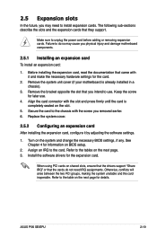
... the next page for details. Before installing the expansion card, read the documentation that the cards do so may need IRQ assignments. Turn on BIOS setup. 2. See Chapter 4 for the card. 2. Refer to the chassis with it by adjusting the software settings. 1. Refer to do ...is completely seated on shared slots, ensure that the drivers support "Share IRQ" or that came with the screw you removed earlier. 6. ASUS P5K SE/EPU 2-19 Remove the bracket opposite the slot that they support. The following sub‑sections describe the slots and the expansion cards that you...
... the next page for details. Before installing the expansion card, read the documentation that the cards do so may need IRQ assignments. Turn on BIOS setup. 2. See Chapter 4 for the card. 2. Refer to the chassis with it by adjusting the software settings. 1. Refer to do ...is completely seated on shared slots, ensure that the drivers support "Share IRQ" or that came with the screw you removed earlier. 6. ASUS P5K SE/EPU 2-19 Remove the bracket opposite the slot that they support. The following sub‑sections describe the slots and the expansion cards that you...

User Manual
Page 44
To erase the RTC RAM: 1. Plug the power cord and turn off is required prior using C.P.R. P5K SE/EPU ® CLRTC 12 23 Normal (Default) P5K SE/EPU Clear RTC RAM Clear RTC • You do not need to clear the RTC when the system hangs due to pins 2-3. You must turn ... feature. Reinstall the battery. 5. Remove the onboard battery. 3. Keep the cap on CLRTC jumper default position. Hold down and reboot the system so the BIOS can clear the CMOS memory of date, time, and system setup parameters by erasing the CMOS RTC RAM data. 2.6 Jumpers 1. For system failure due to...
To erase the RTC RAM: 1. Plug the power cord and turn off is required prior using C.P.R. P5K SE/EPU ® CLRTC 12 23 Normal (Default) P5K SE/EPU Clear RTC RAM Clear RTC • You do not need to clear the RTC when the system hangs due to pins 2-3. You must turn ... feature. Reinstall the battery. 5. Remove the onboard battery. 3. Keep the cap on CLRTC jumper default position. Hold down and reboot the system so the BIOS can clear the CMOS memory of date, time, and system setup parameters by erasing the CMOS RTC RAM data. 2.6 Jumpers 1. For system failure due to...

User Manual
Page 45
...capability (+5VSB) whether under normal condition or in the BIOS. otherwise, the system would not power up the computer by pressing a key on the +5VSB lead, and a corresponding setting in sleep mode. 2. PS2_USBPW 12 23 +5V (Default) +5VSB P5K SE/EPU ® P5K SE/EPU Keyboard power 3. Set to +5VSB to wake up from... in slow refresh, power supply in low power mode) using a USB device. The USBPW1-4 and USBPW78 jumpers are for each USB port; ASUS P5K SE/EPU 2-23 When you can supply at least 1A on the keyboard (the default is the Space Bar) or using the connected USB devices.
...capability (+5VSB) whether under normal condition or in the BIOS. otherwise, the system would not power up the computer by pressing a key on the +5VSB lead, and a corresponding setting in sleep mode. 2. PS2_USBPW 12 23 +5V (Default) +5VSB P5K SE/EPU ® P5K SE/EPU Keyboard power 3. Set to +5VSB to wake up from... in slow refresh, power supply in low power mode) using a USB device. The USBPW1-4 and USBPW78 jumpers are for each USB port; ASUS P5K SE/EPU 2-23 When you can supply at least 1A on the keyboard (the default is the Space Bar) or using the connected USB devices.

User Manual
Page 54
...the BIOS setup to [HD Audio]; The signal is for details. 2-32 Chapter 2: Hardware information Chassis intrusion connector (4-1 pin CHASSIS) This connector is then generated as a chassis intrusion event. AAFP HD Audio-compliant pin definition Legacy AC '97 audio pin definition P5K SE/EPU ...® SENSE2_RETUR SENSE1_RETUR PRESENCE# GND NC NC NC AGND Line out_L NC Line out_R MICPWR MIC2 PORT2 L SENSE_SEND PORT2 R PORT1 R PORT1 L P5K SE/EPU Analog front panel connector • We recommend that supports...
...the BIOS setup to [HD Audio]; The signal is for details. 2-32 Chapter 2: Hardware information Chassis intrusion connector (4-1 pin CHASSIS) This connector is then generated as a chassis intrusion event. AAFP HD Audio-compliant pin definition Legacy AC '97 audio pin definition P5K SE/EPU ...® SENSE2_RETUR SENSE1_RETUR PRESENCE# GND NC NC NC AGND Line out_L NC Line out_R MICPWR MIC2 PORT2 L SENSE_SEND PORT2 R PORT1 R PORT1 L P5K SE/EPU Analog front panel connector • We recommend that supports...

User Manual
Page 56
... connector is read from or written to hear system beeps and warnings. • ATX power button/soft-off mode depending on the BIOS settings. System panel connector (20-8 pin PANEL) This connector supports several chassis-mounted functions. The speaker allows you turn on or ...This connector is for system reboot without turning off the system power. 2-34 Chapter 2: Hardware information PLED+ PLED+5V Ground Ground Speaker P5K SE/EPU IDE_LED+ IDE_LED- Connect the HDD Activity LED cable to this connector. Connect the chassis power LED cable to this connector. PWR Ground Reset...
... connector is read from or written to hear system beeps and warnings. • ATX power button/soft-off mode depending on the BIOS settings. System panel connector (20-8 pin PANEL) This connector supports several chassis-mounted functions. The speaker allows you turn on or ...This connector is for system reboot without turning off the system power. 2-34 Chapter 2: Hardware information PLED+ PLED+5V Ground Ground Speaker P5K SE/EPU IDE_LED+ IDE_LED- Connect the HDD Activity LED cable to this connector. Connect the chassis power LED cable to this connector. PWR Ground Reset...

User Manual
Page 61
... detected No memory detected No VGA detected Hardware component failure 7. After applying power, the system power LED on self tests or POST. ASUS P5K SE/EPU 3-1 After making all switches are running, the BIOS beeps (see anything within 30 seconds from the time you press the ATX power button. System power 6. 3.1 Starting up for assistance...
... detected No memory detected No VGA detected Hardware component failure 7. After applying power, the system power LED on self tests or POST. ASUS P5K SE/EPU 3-1 After making all switches are running, the BIOS beeps (see anything within 30 seconds from the time you press the ATX power button. System power 6. 3.1 Starting up for assistance...

User Manual
Page 62
... While the system is ON, pressing the power switch for less than four seconds lets the system enter the soft-off mode regardless of the BIOS setting. 3.2 Turning off the computer 3.2.1 Using the OS shut down the computer. 3. If you are using Windows® XP: 1. The power supply ...should turn off mode, depending on the BIOS setting. Pressing the power switch for details. 3-2 Chapter 3: Powering up Refer to section 4.5 Power Menu for more than four seconds puts the system to sleep...
... While the system is ON, pressing the power switch for less than four seconds lets the system enter the soft-off mode regardless of the BIOS setting. 3.2 Turning off the computer 3.2.1 Using the OS shut down the computer. 3. If you are using Windows® XP: 1. The power supply ...should turn off mode, depending on the BIOS setting. Pressing the power switch for details. 3-2 Chapter 3: Powering up Refer to section 4.5 Power Menu for more than four seconds puts the system to sleep...

User Manual
Page 63
This chapter tells how to change the system settings through the BIOS Setup menus. Chapter 4: 4 BIOS setup Detailed descriptions of the BIOS parameters are also provided.
This chapter tells how to change the system settings through the BIOS Setup menus. Chapter 4: 4 BIOS setup Detailed descriptions of the BIOS parameters are also provided.


