

Motherboard DIY Troubleshooting Guide
Page 1
P5GV-MX Motherboard
P5GV-MX Motherboard

Motherboard DIY Troubleshooting Guide
Page 3
Contents Notices vi Safety information vii About this guide viii Typography ix P5GV-MX specifications summary x Chapter 1: Product introduction 1.1 Welcome 1-2 1.2 Package contents 1-2 1.3 Special features 1-3 1.3.1 Product highlights 1-3 1.3.2 Innovative ASUS features 1-5 1.4 Before you proceed 1-6 1.5 Motherboard overview 1-7 1.5.1 Placement direction 1-7 1.5.2 Screw holes 1-7 1.5.3 Motherboard layout 1-8 1.6 Central Processing Unit (CPU 1-9 1.6.1 Installing the CPU 1-9 1.6.2 Installing the CPU heatsink and fan 1-12...
Contents Notices vi Safety information vii About this guide viii Typography ix P5GV-MX specifications summary x Chapter 1: Product introduction 1.1 Welcome 1-2 1.2 Package contents 1-2 1.3 Special features 1-3 1.3.1 Product highlights 1-3 1.3.2 Innovative ASUS features 1-5 1.4 Before you proceed 1-6 1.5 Motherboard overview 1-7 1.5.1 Placement direction 1-7 1.5.2 Screw holes 1-7 1.5.3 Motherboard layout 1-8 1.6 Central Processing Unit (CPU 1-9 1.6.1 Installing the CPU 1-9 1.6.2 Installing the CPU heatsink and fan 1-12...

Motherboard DIY Troubleshooting Guide
Page 7
.... If you detect any area where it may become wet. • Place the product on it by yourself. Operation safety • Before installing the motherboard and adding devices on a stable surface. • If you add a device. • Before connecting or removing signal cables from the... motherboard, ensure that all power cables are not damaged. If possible, disconnect all power cables from the existing system before you encounter technical problems with ...
.... If you detect any area where it may become wet. • Place the product on it by yourself. Operation safety • Before installing the motherboard and adding devices on a stable surface. • If you add a device. • Before connecting or removing signal cables from the... motherboard, ensure that all power cables are not damaged. If possible, disconnect all power cables from the existing system before you encounter technical problems with ...

Motherboard DIY Troubleshooting Guide
Page 8
... products. This chapter also lists the hardware setup procedures that the motherboard supports. ASUS websites The ASUS website provides updated information on the motherboard. • Chapter 2: BIOS setup This chapter tells how to the ASUS contact information. 2. Detailed descriptions of the BIOS parameters are not... part of the support CD that comes with the motherboard package. • Appendix: CPU features The appendix describes the CPU features ...
... products. This chapter also lists the hardware setup procedures that the motherboard supports. ASUS websites The ASUS website provides updated information on the motherboard. • Chapter 2: BIOS setup This chapter tells how to the ASUS contact information. 2. Detailed descriptions of the BIOS parameters are not... part of the support CD that comes with the motherboard package. • Appendix: CPU features The appendix describes the CPU features ...

Motherboard DIY Troubleshooting Guide
Page 13
This chapter describes the motherboard features and the new technologies it supports. 1Product introduction ASUS P5GV-MX 1-1
This chapter describes the motherboard features and the new technologies it supports. 1Product introduction ASUS P5GV-MX 1-1
Motherboard DIY Troubleshooting Guide
Page 14
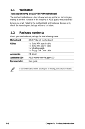
...the following items. Motherboard ASUS P5GV-MX motherboard Cables 1 x Serial ATA signal cable 1 x Serial ATA power cable 1 x UltraDMA cable 1 x Floppy Disk Drive cable Accessories I/O shield Application CDs ASUS motherboard support CD Documentation User guide If any of ASUS quality motherboards! The motherboard delivers a host ...the long line of the above items is damaged or missing, contact your motherboard package for buying an ASUS® P5GV-MX motherboard! Thank you start installing the motherboard, and hardware devices on it another standout in your package with the list ...
...the following items. Motherboard ASUS P5GV-MX motherboard Cables 1 x Serial ATA signal cable 1 x Serial ATA power cable 1 x UltraDMA cable 1 x Floppy Disk Drive cable Accessories I/O shield Application CDs ASUS motherboard support CD Documentation User guide If any of ASUS quality motherboards! The motherboard delivers a host ...the long line of the above items is damaged or missing, contact your motherboard package for buying an ASUS® P5GV-MX motherboard! Thank you start installing the motherboard, and hardware devices on it another standout in your package with the list ...

Motherboard DIY Troubleshooting Guide
Page 15
.... See page 1-9 for details. Intel® EM64T The motherboard supports Intel® Pentium® 4 processors with a 775-pin surface mount Land Grid Array (LGA) socket designed for more efficient computing. ASUS P5GV-MX 1-3 CPU Lock Free This feature allows you to adjust the... chipset The Intel® 915GV Graphics Memory Controller Hub (GMCH) and the ICH6 I /O controller hub that provides the interface for the motherboard. The Intel® ICH6 Southbridge represents the sixth generation I /O controller hub provide the vital interfaces for PCI Express and Serial ATA....
.... See page 1-9 for details. Intel® EM64T The motherboard supports Intel® Pentium® 4 processors with a 775-pin surface mount Land Grid Array (LGA) socket designed for more efficient computing. ASUS P5GV-MX 1-3 CPU Lock Free This feature allows you to adjust the... chipset The Intel® 915GV Graphics Memory Controller Hub (GMCH) and the ICH6 I /O controller hub that provides the interface for the motherboard. The Intel® ICH6 Southbridge represents the sixth generation I /O controller hub provide the vital interfaces for PCI Express and Serial ATA....

Motherboard DIY Troubleshooting Guide
Page 16
...powerful audio and speaker systems. See pages 1-32 for the latest 3D graphics, multimedia, and Internet applications. Serial ATA technology The motherboard supports the Serial ATA technology through the midboard S/PDIF interface. Allows you to -point serial interconnections between devices and allows higher ...clockspeeds by carrying data in packets. See page 1-26 for details. See page 1-16 for details. 6-channel audio The motherboard comes with existing PCI specifications. PCI Express features point-to play online games without buying expensive additional LAN cards. The ...
...powerful audio and speaker systems. See pages 1-32 for the latest 3D graphics, multimedia, and Internet applications. Serial ATA technology The motherboard supports the Serial ATA technology through the midboard S/PDIF interface. Allows you to -point serial interconnections between devices and allows higher ...clockspeeds by carrying data in packets. See page 1-26 for details. See page 1-16 for details. 6-channel audio The motherboard comes with existing PCI specifications. PCI Express features point-to play online games without buying expensive additional LAN cards. The ...

Motherboard DIY Troubleshooting Guide
Page 17
...faster 480Mbps on USB 2.0. See details on USB 1.1 to prevent overheating and damage. See page 2-30 for details. C.P.R. (CPU Parameter Recall) The C.P.R. ASUS P5GV-MX 1-5 See page 2-33 for timely failure detection. eliminates the need to overclocking. USB 2.0 is backward compatible with customizable boot logos. Temperature, fan, and voltage... minute (RPM) is monitored by the Winbond Super I /O monitors the voltage levels to ensure stable supply of the motherboard BIOS allows automatic restore to the BIOS default settings in case the system hangs due to buy a replacement ROM chip...
...faster 480Mbps on USB 2.0. See details on USB 1.1 to prevent overheating and damage. See page 2-30 for details. C.P.R. (CPU Parameter Recall) The C.P.R. ASUS P5GV-MX 1-5 See page 2-33 for timely failure detection. eliminates the need to overclocking. USB 2.0 is backward compatible with customizable boot logos. Temperature, fan, and voltage... minute (RPM) is monitored by the Winbond Super I /O monitors the voltage levels to ensure stable supply of the motherboard BIOS allows automatic restore to the BIOS default settings in case the system hangs due to buy a replacement ROM chip...

Motherboard DIY Troubleshooting Guide
Page 18
... below shows the location of the above articles. 1.4 Before you proceed Take note of the following precautions before you install motherboard components or change any motherboard setting. • Unplug the power cord from the power supply. Failure to do so may cause severe damage to indicate...in sleep mode, or in the bag that came with a standby power LED that lights up to the motherboard, peripherals, or components, or all of the onboard LED. ® P5GV-MX P5GV-MX Onboard LED SB_PWR ON Standby Power OFF Powered Off 1-6 Chapter 1: Product introduction This is a reminder that ...
... below shows the location of the above articles. 1.4 Before you proceed Take note of the following precautions before you install motherboard components or change any motherboard setting. • Unplug the power cord from the power supply. Failure to do so may cause severe damage to indicate...in sleep mode, or in the bag that came with a standby power LED that lights up to the motherboard, peripherals, or components, or all of the onboard LED. ® P5GV-MX P5GV-MX Onboard LED SB_PWR ON Standby Power OFF Powered Off 1-6 Chapter 1: Product introduction This is a reminder that ...
Motherboard DIY Troubleshooting Guide
Page 19
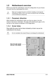
...! The edge with external ports goes to do so can damage the motherboard. ® Place this side towards the rear of the chassis P5GV-MX ASUS P5GV-MX 1-7 Make sure to the chassis. Failure to the rear part of your chassis to ensure that the motherboard fits into it into the chassis in the image below...
...! The edge with external ports goes to do so can damage the motherboard. ® Place this side towards the rear of the chassis P5GV-MX ASUS P5GV-MX 1-7 Make sure to the chassis. Failure to the rear part of your chassis to ensure that the motherboard fits into it into the chassis in the image below...

Motherboard DIY Troubleshooting Guide
Page 20
1.5.3 Motherboard layout PS/2KBMS KBPWR T: Mouse B: Keyboard COM1 ATX12V 24.5cm(9.6in) CHA_FAN CPU_FAN LGA775 Super I/O FLOPPY DDR DIMM_B1 (64 bit,184-pin module) DDR DIMM_B2 (...:Rear Speaker Out Center: Side Speaker Out Below: Center/Subwoofer Intel® 915GV MCH EATXPWR PRI_IDE PCIEX16(x4 mode) RTL8100C PCI1 AD1986A AAFP CD PCI2 P5GV-MX PCI3 SB_PWR SPDIF_OUT CR2032 3V Lithium Cell CMOS Power Intel ICH6 SATA4 SATA3 SATA2 SATA1 CLRTC USB56 USBPW78 USBPW56 USB78 4Mb BIOS PANEL 24.5cm...
1.5.3 Motherboard layout PS/2KBMS KBPWR T: Mouse B: Keyboard COM1 ATX12V 24.5cm(9.6in) CHA_FAN CPU_FAN LGA775 Super I/O FLOPPY DDR DIMM_B1 (64 bit,184-pin module) DDR DIMM_B2 (...:Rear Speaker Out Center: Side Speaker Out Below: Center/Subwoofer Intel® 915GV MCH EATXPWR PRI_IDE PCIEX16(x4 mode) RTL8100C PCI1 AD1986A AAFP CD PCI2 P5GV-MX PCI3 SB_PWR SPDIF_OUT CR2032 3V Lithium Cell CMOS Power Intel ICH6 SATA4 SATA3 SATA2 SATA1 CLRTC USB56 USBPW78 USBPW56 USB78 4Mb BIOS PANEL 24.5cm...

Motherboard DIY Troubleshooting Guide
Page 21
... a surface mount LGA775 socket designed for the CPU, fan and heatsink assembly. Contact your left. ASUS P5GV-MX 1-9 ASUS will process Return Merchandise Authorization (RMA) requests only if the motherboard comes with installation instructions for the Intel® Pentium® 4 processor in this section do not... load lever is shipment/transit-related. • Keep the cap after installing the motherboard. ASUS shoulders the repair cost only if the damage is on the motherboard. ® P5GV-MX P5GV-MX CPU Socket 775 Before installing the CPU, make sure that the socket box is ...
... a surface mount LGA775 socket designed for the CPU, fan and heatsink assembly. Contact your left. ASUS P5GV-MX 1-9 ASUS will process Return Merchandise Authorization (RMA) requests only if the motherboard comes with installation instructions for the Intel® Pentium® 4 processor in this section do not... load lever is shipment/transit-related. • Keep the cap after installing the motherboard. ASUS shoulders the repair cost only if the damage is on the motherboard. ® P5GV-MX P5GV-MX CPU Socket 775 Before installing the CPU, make sure that the socket box is ...
Motherboard DIY Troubleshooting Guide
Page 23
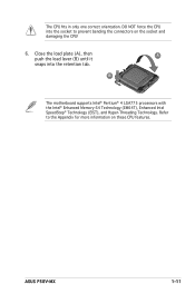
B The motherboard supports Intel® Pentium® 4 LGA775 processors with the Intel® Enhanced Memory 64 Technology (EM64T), Enhanced Intel SpeedStep® Technology (EIST), and Hyper-Threading Technology. Refer to prevent bending the connectors on these CPU features. Close the load plate (A), then push the load lever (B) until it A snaps into the socket to the Appendix for more information on the socket and damaging the CPU! 6. DO NOT force the CPU into the retention tab. ASUS P5GV-MX 1-11 The CPU fits in only one correct orientation.
B The motherboard supports Intel® Pentium® 4 LGA775 processors with the Intel® Enhanced Memory 64 Technology (EM64T), Enhanced Intel SpeedStep® Technology (EIST), and Hyper-Threading Technology. Refer to prevent bending the connectors on these CPU features. Close the load plate (A), then push the load lever (B) until it A snaps into the socket to the Appendix for more information on the socket and damaging the CPU! 6. DO NOT force the CPU into the retention tab. ASUS P5GV-MX 1-11 The CPU fits in only one correct orientation.

Motherboard DIY Troubleshooting Guide
Page 24
...only Intel®-certified multi-directional heatsink and fan. • Make sure that the four fasteners match the holes on the motherboard. 1.6.2 Installing the CPU heatsink and fan The Intel® Pentium® 4 LGA775 processor requires a specially designed heatsink and fan ...assembly to ensure optimum thermal condition and performance. • Install the motherboard to the chassis before you install the CPU fan and heatsink assembly. • Your Intel® Pentium® 4 LGA775 heatsink and fan...
...only Intel®-certified multi-directional heatsink and fan. • Make sure that the four fasteners match the holes on the motherboard. 1.6.2 Installing the CPU heatsink and fan The Intel® Pentium® 4 LGA775 processor requires a specially designed heatsink and fan ...assembly to ensure optimum thermal condition and performance. • Install the motherboard to the chassis before you install the CPU fan and heatsink assembly. • Your Intel® Pentium® 4 LGA775 heatsink and fan...

Motherboard DIY Troubleshooting Guide
Page 25
When the fan and heatsink assembly is in place, connect the CPU fan cable to secure the heatsink and fan assembly in a diagonal sequence to the connector on the motherboard labeled CPU_FAN. B A A A B B B A 3. Push down two fasteners at a time in place. ASUS P5GV-MX 1-13 CPU_FAN ® GND CPU FAN PWR CPU FAN IN CPU FAN PWM 1 P5GV-MX P5GV-MX CPU Fan Connector Do not forget to plug this connector. Hardware monitoring errors can occur if you fail to connect the CPU fan connector! 2.
When the fan and heatsink assembly is in place, connect the CPU fan cable to secure the heatsink and fan assembly in a diagonal sequence to the connector on the motherboard labeled CPU_FAN. B A A A B B B A 3. Push down two fasteners at a time in place. ASUS P5GV-MX 1-13 CPU_FAN ® GND CPU FAN PWR CPU FAN IN CPU FAN PWM 1 P5GV-MX P5GV-MX CPU Fan Connector Do not forget to plug this connector. Hardware monitoring errors can occur if you fail to connect the CPU fan connector! 2.

Motherboard DIY Troubleshooting Guide
Page 26
Rotate each fastener counterclockwise. 3. B A B B A 1-14 Chapter 1: Product introduction Disconnect the CPU fan cable from the A A motherboard. Pull up two fasteners at a time in a diagonal sequence to disengage the heatsink B and fan assembly from the connector on the motherboard. 2. 1.6.3 Uninstalling the CPU heatsink and fan To uninstall the CPU heatsink and fan: 1.
Rotate each fastener counterclockwise. 3. B A B B A 1-14 Chapter 1: Product introduction Disconnect the CPU fan cable from the A A motherboard. Pull up two fasteners at a time in a diagonal sequence to disengage the heatsink B and fan assembly from the connector on the motherboard. 2. 1.6.3 Uninstalling the CPU heatsink and fan To uninstall the CPU heatsink and fan: 1.

Motherboard DIY Troubleshooting Guide
Page 27
Remove the heatsink and fan assembly from the motherboard. 5. Rotate each fastener should be oriented as shown, with the narrow groove directed outward. 4. When reset, each fastener clockwise to reset the orientation. Narrow end of the groove ASUS P5GV-MX 1-15
Remove the heatsink and fan assembly from the motherboard. 5. Rotate each fastener should be oriented as shown, with the narrow groove directed outward. 4. When reset, each fastener clockwise to reset the orientation. Narrow end of the groove ASUS P5GV-MX 1-15

Motherboard DIY Troubleshooting Guide
Page 28
...; XP 32-bit operationg system, we recommend you obtain memory modules from the same vendor. Use any of the sockets: ® DIMM_A1 DIMM_A2 DIMM_B1 DIMM_B2 P5GV-MX P5GV-MX 184-pin DDR DIMM Sockets 1.7.2 Memory Configurations You may install 256 MB, 512 MB and 1 GB unbuffered non-ECC DDR DIMMs into the DIMM sockets... system since it is recommended that you to systms with 128 Mb memory chips or double-sided x16 memory chips are not supported in this motherboard. • When you installed four 1 GB DDR memory modules, the system may cause memory sizing error or system boot failure.
...; XP 32-bit operationg system, we recommend you obtain memory modules from the same vendor. Use any of the sockets: ® DIMM_A1 DIMM_A2 DIMM_B1 DIMM_B2 P5GV-MX P5GV-MX 184-pin DDR DIMM Sockets 1.7.2 Memory Configurations You may install 256 MB, 512 MB and 1 GB unbuffered non-ECC DDR DIMMs into the DIMM sockets... system since it is recommended that you to systms with 128 Mb memory chips or double-sided x16 memory chips are not supported in this motherboard. • When you installed four 1 GB DDR memory modules, the system may cause memory sizing error or system boot failure.

Motherboard DIY Troubleshooting Guide
Page 31
... out with your fingers when pressing the retaining clips. ASUS P5GV-MX 1-19 DO NOT force a DIMM into the socket until the retaining clips snap back in only one direction. Remove the DIMM from the socket. 1.7.3 Installing a DIMM Make sure to both the motherboard and the components. 1. Locked Retaining Clip 1.7.4 Removing a DIMM Follow...
... out with your fingers when pressing the retaining clips. ASUS P5GV-MX 1-19 DO NOT force a DIMM into the socket until the retaining clips snap back in only one direction. Remove the DIMM from the socket. 1.7.3 Installing a DIMM Make sure to both the motherboard and the components. 1. Locked Retaining Clip 1.7.4 Removing a DIMM Follow...


