
User Manual
Page 1
P5GDC Pro Motherboard
P5GDC Pro Motherboard
User Manual
Page 3
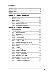
Contents Notices vii Safety information viii Operation safety viii P5GDC Pro specifications summary ix Chapter 1: Product introduction 1.1 Welcome 2-1 1.2 Package contents 2-1 1.3 Special features 2-2 1.3.1 Product highlights 2-2 1.3.2 ASUS Proactive features 2-4 1.3.3 Innovative ASUS features 2-5 Chapter 2: Hardware information 2.1 Before you proceed 2-1 2.2 Motherboard overview 2-2 2.2.1 Placement direction 2-2 2.2.2 Screw holes 2-2 2.2.3 Motherboard layout 2-3 2.2.4 Layout Contents 2-4 2.3 Central Processing Unit (CPU 2-6 2.3.1 Installing the CPU 2-6 2.3.2 Installing ...
Contents Notices vii Safety information viii Operation safety viii P5GDC Pro specifications summary ix Chapter 1: Product introduction 1.1 Welcome 2-1 1.2 Package contents 2-1 1.3 Special features 2-2 1.3.1 Product highlights 2-2 1.3.2 ASUS Proactive features 2-4 1.3.3 Innovative ASUS features 2-5 Chapter 2: Hardware information 2.1 Before you proceed 2-1 2.2 Motherboard overview 2-2 2.2.1 Placement direction 2-2 2.2.2 Screw holes 2-2 2.2.3 Motherboard layout 2-3 2.2.4 Layout Contents 2-4 2.3 Central Processing Unit (CPU 2-6 2.3.1 Installing the CPU 2-6 2.3.2 Installing ...
User Manual
Page 9
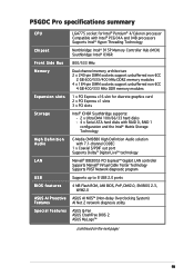
P5GDC Pro specifications summary CPU Chipset Front Side Bus Memory Expansion slots Storage High Definition Audio LAN USB BIOS features ASUS AI Proactive Features Special features LGA775 socket for Intel® Pentium® 4/Celeron processor Compatible with Intel® PCG 04A and ... Technology Supports POST Network diagnostic program Supports up to 8 USB 2.0 ports 4 MB Flash ROM, AMI BIOS, PnP, DMI2.0, SM BIOS 2.3, WfM2.0 ASUS AI NOS™ (Non-delay Overclocking System) AI Net 2 network diagnosis utility ASUS Q-Fan ASUS CrashFree BIOS 2 ASUS MyLogo™ (continued on the next page) ix
P5GDC Pro specifications summary CPU Chipset Front Side Bus Memory Expansion slots Storage High Definition Audio LAN USB BIOS features ASUS AI Proactive Features Special features LGA775 socket for Intel® Pentium® 4/Celeron processor Compatible with Intel® PCG 04A and ... Technology Supports POST Network diagnostic program Supports up to 8 USB 2.0 ports 4 MB Flash ROM, AMI BIOS, PnP, DMI2.0, SM BIOS 2.3, WfM2.0 ASUS AI NOS™ (Non-delay Overclocking System) AI Net 2 network diagnosis utility ASUS Q-Fan ASUS CrashFree BIOS 2 ASUS MyLogo™ (continued on the next page) ix
User Manual
Page 10
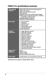
x P5GDC Pro specifications summary Overclocking features Rear panel Internal connectors Support CD contents Form factor ASUS AI NOS™ (Non-delay Overclocking System) ASUS AI Overclocking ASUS C.P.R. (CPU Parameter Recall) ASUS AI Booster Adjustable CPU, memory, and PCI Express voltages Stepless Frequency ... 1 x Game/MIDI port connector 1 x Chassis intrusion connector 1 x Front panel High Definition Audio connector 1 x System panel connector Drivers ASUS PC Probe ASUS Live Update Anti-virus software (OEM version) ATX form factor: 12 in x 9.6 in (30.5 cm x 24.4 cm) Specifications are...
x P5GDC Pro specifications summary Overclocking features Rear panel Internal connectors Support CD contents Form factor ASUS AI NOS™ (Non-delay Overclocking System) ASUS AI Overclocking ASUS C.P.R. (CPU Parameter Recall) ASUS AI Booster Adjustable CPU, memory, and PCI Express voltages Stepless Frequency ... 1 x Game/MIDI port connector 1 x Chassis intrusion connector 1 x Front panel High Definition Audio connector 1 x System panel connector Drivers ASUS PC Probe ASUS Live Update Anti-virus software (OEM version) ATX form factor: 12 in x 9.6 in (30.5 cm x 24.4 cm) Specifications are...
User Manual
Page 13
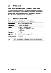
... you for the following items. Motherboard I/O module Cables Accessory Application CD Documentation ASUS P5GDC Pro motherboard 1 x Serial port module 2 x Serial ATA signal cables 1 x Ultra DMA 133/100/66 cable 1 x FDD cable I/O shield ASUS motherboard support CD User guide If any of ASUS quality motherboards! The motherboard delivers a host of new features and latest technologies, ...the motherboard, and hardware devices on it another standout in your package with the list below. 1.2 Package contents Check your motherboard package for buying an ASUS® P5GDC Pro motherboard!
... you for the following items. Motherboard I/O module Cables Accessory Application CD Documentation ASUS P5GDC Pro motherboard 1 x Serial port module 2 x Serial ATA signal cables 1 x Ultra DMA 133/100/66 cable 1 x FDD cable I/O shield ASUS motherboard support CD User guide If any of ASUS quality motherboards! The motherboard delivers a host of new features and latest technologies, ...the motherboard, and hardware devices on it another standout in your package with the list below. 1.2 Package contents Check your motherboard package for buying an ASUS® P5GDC Pro motherboard!
User Manual
Page 15
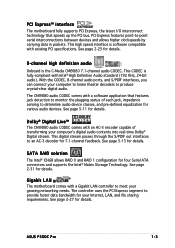
... clockspeeds by carrying data in packets. With the CODEC, 8-channel audio ports, and S/PDIF interfaces, you can connect your Internet, LAN, and file sharing requirements. ASUS P5GDC Pro 1-3
... clockspeeds by carrying data in packets. With the CODEC, 8-channel audio ports, and S/PDIF interfaces, you can connect your Internet, LAN, and file sharing requirements. ASUS P5GDC Pro 1-3
User Manual
Page 17
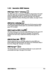
... the BIOS codes and data are corrupted. See page 4-2 for details. ASUS EZ Flash BIOS With the ASUS EZ Flash, you to personalize and add style to ensure quiet, cool, and efficient operation. ASUS P5GDC Pro 1-5 Enabling Hyper Path 2 on systems with customizable boot logos. ASUS CrashFree BIOS 2 This feature allows you to buy a replacement ROM...
... the BIOS codes and data are corrupted. See page 4-2 for details. ASUS EZ Flash BIOS With the ASUS EZ Flash, you to personalize and add style to ensure quiet, cool, and efficient operation. ASUS P5GDC Pro 1-5 Enabling Hyper Path 2 on systems with customizable boot logos. ASUS CrashFree BIOS 2 This feature allows you to buy a replacement ROM...

User Manual
Page 20
Chapter summary 2 2.1 Before you proceed 2-1 2.2 Motherboard overview 2-2 2.3 Central Processing Unit (CPU 2-6 2.4 System memory 2-13 2.5 Expansion slots 2-21 2.6 Jumpers 2-24 2.7 Connectors 2-27 ASUS P5GDC Pro
Chapter summary 2 2.1 Before you proceed 2-1 2.2 Motherboard overview 2-2 2.3 Central Processing Unit (CPU 2-6 2.4 System memory 2-13 2.5 Expansion slots 2-21 2.6 Jumpers 2-24 2.7 Connectors 2-27 ASUS P5GDC Pro

User Manual
Page 21
... that lights up to indicate that the system is switched off mode. 2.1 Before you proceed Take note of the onboard LED. P5GDC PRO SB_PWR1 ON Standby P5GDC PRO Onboard LED Power OFF Powered Off ASUS P5GDC Pro 2-1 Failure to do so may cause severe damage to the motherboard, peripherals, and/or components. This is a reminder that the...
... that lights up to indicate that the system is switched off mode. 2.1 Before you proceed Take note of the onboard LED. P5GDC PRO SB_PWR1 ON Standby P5GDC PRO Onboard LED Power OFF Powered Off ASUS P5GDC Pro 2-1 Failure to do so may cause severe damage to the motherboard, peripherals, and/or components. This is a reminder that the...

User Manual
Page 22
... the holes indicated by circles to secure the motherboard to the chassis. The edge with external ports goes to the rear part of the chassis P5GDC PRO 2-2 Chapter 2: Hardware information Doing so can cause you place it . Refer to unplug the power cord before installing the motherboard. Make sure to the chassis...
... the holes indicated by circles to secure the motherboard to the chassis. The edge with external ports goes to the rear part of the chassis P5GDC PRO 2-2 Chapter 2: Hardware information Doing so can cause you place it . Refer to unplug the power cord before installing the motherboard. Make sure to the chassis...

User Manual
Page 23
... Out Center: Side Speaker Out Below: Center/Subwoofer Top:Line In Center:Line Out Below:Mic In PWR_FAN1 Intel R MCH 915P PRI_IDE1 Marvell 88E8053 CHA_FAN2 P5GDC PRO PCIEX16 PCI1 PCI2 PCI3 AAFP PCIEX1_1 CMI9880 SB_PWR1 PCIEX1_2 CD COM1 R Intel ICH6R SATA3 SATA4 CR2032 3V Lithium Cell CMOS Power CLRTC1 USB56 USB78 USBPW56...
... Out Center: Side Speaker Out Below: Center/Subwoofer Top:Line In Center:Line Out Below:Mic In PWR_FAN1 Intel R MCH 915P PRI_IDE1 Marvell 88E8053 CHA_FAN2 P5GDC PRO PCIEX16 PCI1 PCI2 PCI3 AAFP PCIEX1_1 CMI9880 SB_PWR1 PCIEX1_2 CD COM1 R Intel ICH6R SATA3 SATA4 CR2032 3V Lithium Cell CMOS Power CLRTC1 USB56 USB78 USBPW56...

User Manual
Page 25
... (16-1 pin GAME) 13. Reset switch (Blue 2-pin RESET) Page 2-29 2-30 2-31 2-32 2-32 2-32 2-33 2-33 2-34 2-34 2-35 2-35 2-36 2-37 2-38 ASUS P5GDC Pro 2-5 Serial ATA connectors (7-pin SATA1, SATA2, SATA3, SATA4) 4. Hard Disk activity (Red 2-pin IDE_LED) - Front panel audio connector (10-1 pin AAFP) 15. ATX 12V power...
... (16-1 pin GAME) 13. Reset switch (Blue 2-pin RESET) Page 2-29 2-30 2-31 2-32 2-32 2-32 2-33 2-33 2-34 2-34 2-35 2-35 2-36 2-37 2-38 ASUS P5GDC Pro 2-5 Serial ATA connectors (7-pin SATA1, SATA2, SATA3, SATA4) 4. Hard Disk activity (Red 2-pin IDE_LED) - Front panel audio connector (10-1 pin AAFP) 15. ATX 12V power...

User Manual
Page 26
...: 1. Contact your left. 2-6 Chapter 2: Hardware information ASUS will process Return Merchandise Authorization (RMA) requests only if the motherboard comes with installation instructions for the CPU, heatsink, and the retention mechanism. Locate the CPU socket on the socket and the socket contacts are not bent. P5GDC PRO P5GDC PRO CPU Socket 775 Before installing the CPU...
...: 1. Contact your left. 2-6 Chapter 2: Hardware information ASUS will process Return Merchandise Authorization (RMA) requests only if the motherboard comes with installation instructions for the CPU, heatsink, and the retention mechanism. Locate the CPU socket on the socket and the socket contacts are not bent. P5GDC PRO P5GDC PRO CPU Socket 775 Before installing the CPU...
User Manual
Page 27
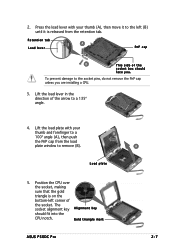
.... 4. Load plate 5. Lift the load lever in the direction of the socket. The socket alignment key A l i g n m e n t k e y should face you are installing a CPU. 3. Gold triangle mark ASUS P5GDC Pro A 2-7 2.
.... 4. Load plate 5. Lift the load lever in the direction of the socket. The socket alignment key A l i g n m e n t k e y should face you are installing a CPU. 3. Gold triangle mark ASUS P5GDC Pro A 2-7 2.

User Manual
Page 29
... includes the CPU fan and heatsink assembly. Place the heatsink on top of the groove pointing outward. (The photo shows the groove shaded for emphasis.) ASUS P5GDC Pro 2-9 2.3.2 Installing the CPU heatsink and fan The Intel® Pentium® 4 LGA775 processor requires a specially designed heatsink and fan assembly to the chassis before you...
... includes the CPU fan and heatsink assembly. Place the heatsink on top of the groove pointing outward. (The photo shows the groove shaded for emphasis.) ASUS P5GDC Pro 2-9 2.3.2 Installing the CPU heatsink and fan The Intel® Pentium® 4 LGA775 processor requires a specially designed heatsink and fan assembly to the chassis before you...

User Manual
Page 30
Hardware monitoring errors can occur if you fail to connect the CPU fan connector! 2. CPU_FAN1 P5GDC PRO GND CPU FAN PWR CPU FAN IN CPU FAN PWM Do not forget to plug this connector. 2-10 Chapter 2: Hardware information Connect the CPU fan cable to secure the B heatsink and fan assembly in A place. Push down two fasteners at a time in a diagonal sequence to the connector on the motherboard labeled CPU_FAN1. A B A B B A 3.
Hardware monitoring errors can occur if you fail to connect the CPU fan connector! 2. CPU_FAN1 P5GDC PRO GND CPU FAN PWR CPU FAN IN CPU FAN PWM Do not forget to plug this connector. 2-10 Chapter 2: Hardware information Connect the CPU fan cable to secure the B heatsink and fan assembly in A place. Push down two fasteners at a time in a diagonal sequence to the connector on the motherboard labeled CPU_FAN1. A B A B B A 3.

User Manual
Page 31
A B A B B A ASUS P5GDC Pro 2-11 Disconnect the CPU fan cable from the A motherboard. Pull up two fasteners at a time in a diagonal sequence to disengage the heatsink B and fan assembly from the connector on the motherboard. 2. 2.3.3 Uninstalling the CPU heatsink and fan To uninstall the CPU heatsink and fan: 1. Rotate each fastener counterclockwise. 3.
A B A B B A ASUS P5GDC Pro 2-11 Disconnect the CPU fan cable from the A motherboard. Pull up two fasteners at a time in a diagonal sequence to disengage the heatsink B and fan assembly from the connector on the motherboard. 2. 2.3.3 Uninstalling the CPU heatsink and fan To uninstall the CPU heatsink and fan: 1. Rotate each fastener counterclockwise. 3.
User Manual
Page 33
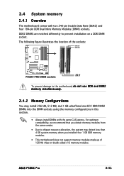
... prevent damage to prevent installation on a DDR DIMM socket. The following figure illustrates the location of 128 Mb chips or double sided x16 memory modules. ASUS P5GDC Pro 2-13 For optimum compatibility, we recommend that you obtain memory modules from the same vendor. • Due to chipset resource allocation, the system may install...
... prevent damage to prevent installation on a DDR DIMM socket. The following figure illustrates the location of 128 Mb chips or double sided x16 memory modules. ASUS P5GDC Pro 2-13 For optimum compatibility, we recommend that you obtain memory modules from the same vendor. • Due to chipset resource allocation, the system may install...

User Manual
Page 37
supports one pair of Dual-channel memory configuration. B - Single-sided D S - Double-sided ASUS P5GDC Pro 2-17 S S - supports one pair of modules inserted into both yellow slots as one module inserted in any yellow slot in a Single-channel memory configuration. DDR2 (...
supports one pair of Dual-channel memory configuration. B - Single-sided D S - Double-sided ASUS P5GDC Pro 2-17 S S - supports one pair of modules inserted into both yellow slots as one module inserted in any yellow slot in a Single-channel memory configuration. DDR2 (...

User Manual
Page 39
... into a socket to unplug the power supply before adding or removing DIMMs or other system components. Unlock a DIMM socket by pressing the retaining clips outward. 2. ASUS P5GDC Pro 2-19 The DIMM might get damaged when it fits in place and the DIMM is keyed with your fingers when pressing the retaining clips. DO...
... into a socket to unplug the power supply before adding or removing DIMMs or other system components. Unlock a DIMM socket by pressing the retaining clips outward. 2. ASUS P5GDC Pro 2-19 The DIMM might get damaged when it fits in place and the DIMM is keyed with your fingers when pressing the retaining clips. DO...


