User Manual
Page 4
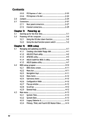
... the computer 3-2 3.2.1 Using the OS shut down function 3-2 3.2.2 Using the dual function power switch 3-2 Chapter 4: BIOS setup 4.1 Managing and updating your BIOS 4-1 4.1.1 Creating a bootable floppy disk 4-1 4.1.2 ASUS EZ Flash utility 4-2 4.1.3 AFUDOS utility 4-3 4.1.4 ASUS CrashFree BIOS 2 utility 4-5 4.1.5 ASUS Update utility 4-7 4.2 BIOS setup program 4-10 4.2.1 BIOS menu screen 4-11 4.2.2 Menu bar 4-11 4.2.3 Navigation keys 4-11 4.2.4 Menu items 4-12 4.2.5 Sub-menu...
... the computer 3-2 3.2.1 Using the OS shut down function 3-2 3.2.2 Using the dual function power switch 3-2 Chapter 4: BIOS setup 4.1 Managing and updating your BIOS 4-1 4.1.1 Creating a bootable floppy disk 4-1 4.1.2 ASUS EZ Flash utility 4-2 4.1.3 AFUDOS utility 4-3 4.1.4 ASUS CrashFree BIOS 2 utility 4-5 4.1.5 ASUS Update utility 4-7 4.2 BIOS setup program 4-10 4.2.1 BIOS menu screen 4-11 4.2.2 Menu bar 4-11 4.2.3 Navigation keys 4-11 4.2.4 Menu items 4-12 4.2.5 Sub-menu...
User Manual
Page 9
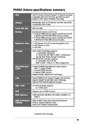
...8212F IDE controller supports: - 2 x Ultra DMA 133/100 /66 - P5GDC Deluxe specifications summary CPU Chipset Front Side Bus Memory Expansion slots Storage High Definition Audio LAN IEEE 1394 USB BIOS features ASUS AI Proactive Features LGA775 socket for Intel® Pentium® 4/Celeron processor Compatible...program TI 1394a controller supports: - 2 x 1394a ports Supports up to 8 USB 2.0 ports 4 MB Flash ROM, AMI BIOS, PnP, DMI2.0, SM BIOS 2.3, WfM2.0 ASUS AI NOS™ (Non-delay Overclocking System) AI Net 2 network diagnosis utility Stack Cool™ fanless cooling system (continued ...
...8212F IDE controller supports: - 2 x Ultra DMA 133/100 /66 - P5GDC Deluxe specifications summary CPU Chipset Front Side Bus Memory Expansion slots Storage High Definition Audio LAN IEEE 1394 USB BIOS features ASUS AI Proactive Features LGA775 socket for Intel® Pentium® 4/Celeron processor Compatible...program TI 1394a controller supports: - 2 x 1394a ports Supports up to 8 USB 2.0 ports 4 MB Flash ROM, AMI BIOS, PnP, DMI2.0, SM BIOS 2.3, WfM2.0 ASUS AI NOS™ (Non-delay Overclocking System) AI Net 2 network diagnosis utility Stack Cool™ fanless cooling system (continued ...

User Manual
Page 10
P5GDC Deluxe specifications summary Overclocking features Special features Rear panel Internal connectors Support CD contents Form factor ASUS AI NOS™ (Non-delay Overclocking System) ASUS AI Overclocking ASUS C.P.R. (CPU Parameter Recall) ASUS AI Booster Adjustable CPU, memory, and PCI Express voltages... Stepless Frequency Selection (SFS) from 100 MHz up to 400 MHz at 1 MHz increment Adjustable FSB/DDR frequencies Fixed PCI/PCI Express frequencies ASUS Q-Fan2 ASUS CrashFree BIOS 2 ASUS MyLogo™ 1 x PS/2 mouse port 1 x Parallel port 1 x IEEE 1394a port 1 x LAN (RJ-45) port 4 ...
P5GDC Deluxe specifications summary Overclocking features Special features Rear panel Internal connectors Support CD contents Form factor ASUS AI NOS™ (Non-delay Overclocking System) ASUS AI Overclocking ASUS C.P.R. (CPU Parameter Recall) ASUS AI Booster Adjustable CPU, memory, and PCI Express voltages... Stepless Frequency Selection (SFS) from 100 MHz up to 400 MHz at 1 MHz increment Adjustable FSB/DDR frequencies Fixed PCI/PCI Express frequencies ASUS Q-Fan2 ASUS CrashFree BIOS 2 ASUS MyLogo™ 1 x PS/2 mouse port 1 x Parallel port 1 x IEEE 1394a port 1 x LAN (RJ-45) port 4 ...
User Manual
Page 17
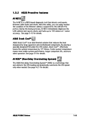
...thermal solution that reduces the heat dissipated by 10º Celsius. See page 5-10 for details. ASUS Stack Cool™ ASUS Stack Cool™ is a BIOS-based diagnostic tool that auto-detects the CPU loading and dynamically overclocks the CPU speed only when needed...by large capacitors and motherboard components. Cooler system temperature means more stable system performance, longer component life, and more silent operation. ASUS P5GDC Deluxe 1-5 See page 2-3 for details. During the bootup process, Ai NET2 immediately diagnoses the LAN cable(s) and reports shorts and ...
...thermal solution that reduces the heat dissipated by 10º Celsius. See page 5-10 for details. ASUS Stack Cool™ ASUS Stack Cool™ is a BIOS-based diagnostic tool that auto-detects the CPU loading and dynamically overclocks the CPU speed only when needed...by large capacitors and motherboard components. Cooler system temperature means more stable system performance, longer component life, and more silent operation. ASUS P5GDC Deluxe 1-5 See page 2-3 for details. During the bootup process, Ai NET2 immediately diagnoses the LAN cable(s) and reports shorts and ...

User Manual
Page 18
...;, the multimedia software package that includes the latest DVD playback and creator, plus a user-friendly MP3 interface. 1-6 Chapter 1: Product introduction ASUS CrashFree BIOS 2 This feature allows you to buy a replacement ROM chip. This protection eliminates the need to your system with customizable boot logos. See... page 4-34 for details. ASUS EZ Flash BIOS With the ASUS EZ Flash, you to personalize and add style to use a DOS-based utility or boot from the support CD in...
...;, the multimedia software package that includes the latest DVD playback and creator, plus a user-friendly MP3 interface. 1-6 Chapter 1: Product introduction ASUS CrashFree BIOS 2 This feature allows you to buy a replacement ROM chip. This protection eliminates the need to your system with customizable boot logos. See... page 4-34 for details. ASUS EZ Flash BIOS With the ASUS EZ Flash, you to personalize and add style to use a DOS-based utility or boot from the support CD in...
User Manual
Page 29
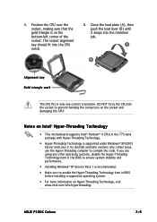
... using any other operating systems, disable the Hyper-Threading Technology item in the BIOS to enable the Hyper-Threading Technology item in BIOS before installing a supported operating system. • For more information on the socket and damaging the CPU! ASUS P5GDC Deluxe 2-9 Notes on the bottom-left corner of the socket. 5. A B Alignment key Gold triangle...
... using any other operating systems, disable the Hyper-Threading Technology item in the BIOS to enable the Hyper-Threading Technology item in BIOS before installing a supported operating system. • For more information on the socket and damaging the CPU! ASUS P5GDC Deluxe 2-9 Notes on the bottom-left corner of the socket. 5. A B Alignment key Gold triangle...
User Manual
Page 30
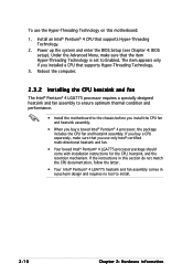
... buy a boxed Intel® Pentium® 4 processor, the package includes the CPU fan and heatsink assembly. Power up the system and enter the BIOS Setup (see Chapter 4: BIOS setup). The item appears only if you buy a CPU separately, make sure that you use the Hyper-Threading Technology on this section do not...
... buy a boxed Intel® Pentium® 4 processor, the package includes the CPU fan and heatsink assembly. Power up the system and enter the BIOS Setup (see Chapter 4: BIOS setup). The item appears only if you buy a CPU separately, make sure that you use the Hyper-Threading Technology on this section do not...

User Manual
Page 41
... system and change the necessary BIOS settings, if any. Install the software drivers for information on the slot. 5. Turn on the next page. 3. See Chapter 4 for the expansion card. Refer to install expansion cards. Make sure to the card. ASUS P5GDC Deluxe 2-21 The following sub-sections... IRQ to unplug the power cord before adding or removing expansion cards. Remove the system unit cover (if your motherboard is completely seated on BIOS setup. 2. Keep the screw for the card. 2. Secure the card to use . 4. Replace the system cover. 2.5.2 Configuring an expansion...
... system and change the necessary BIOS settings, if any. Install the software drivers for information on the slot. 5. Turn on the next page. 3. See Chapter 4 for the expansion card. Refer to install expansion cards. Make sure to the card. ASUS P5GDC Deluxe 2-21 The following sub-sections... IRQ to unplug the power cord before adding or removing expansion cards. Remove the system unit cover (if your motherboard is completely seated on BIOS setup. 2. Keep the screw for the card. 2. Secure the card to use . 4. Replace the system cover. 2.5.2 Configuring an expansion...
User Manual
Page 44
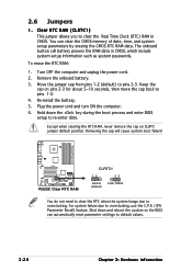
...3. P5GDC P5GDC Clear RTC RAM CLRTC1 12 23 Normal (Default) Clear CMOS You do not need to clear the RTC when the system hangs due to pins 2-3. You can automatically reset parameter settings to default values. 2-24 Chapter 2: Hardware information Hold down and reboot the system so the BIOS can ... RTC RAM data. Keep the cap on CLRTC jumper default position. Re-install the battery. 5. Shut down the key during the boot process and enter BIOS setup to pins 1-2. 4. To erase the RTC RAM: 1. Turn OFF the computer and unplug the power cord. 2. Move the jumper cap from pins ...
...3. P5GDC P5GDC Clear RTC RAM CLRTC1 12 23 Normal (Default) Clear CMOS You do not need to clear the RTC when the system hangs due to pins 2-3. You can automatically reset parameter settings to default values. 2-24 Chapter 2: Hardware information Hold down and reboot the system so the BIOS can ... RTC RAM data. Keep the cap on CLRTC jumper default position. Re-install the battery. 5. Shut down the key during the boot process and enter BIOS setup to pins 1-2. 4. To erase the RTC RAM: 1. Turn OFF the computer and unplug the power cord. 2. Move the jumper cap from pins ...
User Manual
Page 46
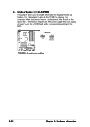
KBPWR1 12 23 +5V +5VSB (Default) P5GDC P5GDC Keyboard power setting 2-26 Chapter 2: Hardware information This feature requires an ATX power supply that can supply at least 1A on the keyboard (the default is the Space Bar). 3. Set this jumper to pins 2-3 (+5VSB) to enable or disable the keyboard wake-up the computer when you to wake up feature. Keyboard power (3-pin KBPWR) This jumper allows you press a key on the +5VSB lead, and a corresponding setting in the BIOS.
KBPWR1 12 23 +5V +5VSB (Default) P5GDC P5GDC Keyboard power setting 2-26 Chapter 2: Hardware information This feature requires an ATX power supply that can supply at least 1A on the keyboard (the default is the Space Bar). 3. Set this jumper to pins 2-3 (+5VSB) to enable or disable the keyboard wake-up the computer when you to wake up feature. Keyboard power (3-pin KBPWR) This jumper allows you press a key on the +5VSB lead, and a corresponding setting in the BIOS.
User Manual
Page 50
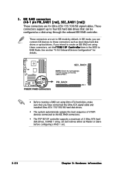
...[red], SEC_RAID1 [red]) These connectors are set . 2-30 Chapter 2: Hardware information SEC_RAID1 NOTE: Orient the red markings (usually zigzag) on the IDE P5GDC cable to the IDE RAID connectors. • The ITE® 8212F controller supports a maximum of 2 Ultra ATA hard disk drives. In RAID 1 ... that you intend to create an IDE RAID set using these connectors, set the I T E 8 2 1 2 F C o n t r o l l e r item in the BIOS to these connectors such as a disk array through the onboard IDE RAID controller. These connectors are for details. If you have connected the Ultra ATA...
...[red], SEC_RAID1 [red]) These connectors are set . 2-30 Chapter 2: Hardware information SEC_RAID1 NOTE: Orient the red markings (usually zigzag) on the IDE P5GDC cable to the IDE RAID connectors. • The ITE® 8212F controller supports a maximum of 2 Ultra ATA hard disk drives. In RAID 1 ... that you intend to create an IDE RAID set using these connectors, set the I T E 8 2 1 2 F C o n t r o l l e r item in the BIOS to these connectors such as a disk array through the onboard IDE RAID controller. These connectors are for details. If you have connected the Ultra ATA...

User Manual
Page 51
Refer to these connectors, set the C o n f i g u r e S A T A A s item in the BIOS to support S3 function. These connectors are set . • Plug your Serial ATA boot disk on the master port (SATA1 and SATA2) ...Master/Slave connectors Connector Color Setting SATA1, SATA2 Red Master SATA3, SATA4 Black Slave Use Boot Disk Data Disk ASUS P5GDC Deluxe 2-31 See section "4.3.6 IDE Configuration" for details. SATA3 SATA4 P5GDC GND RSATA_TXP4 RSATA_TXN4 GND RSATA_RXP4 RSATA_RXN4 GND GND RSATA_TXP3 RSATA_TXN3 GND RSATA_RXP3 RSATA_RXN3 GND SATA1 SATA2 GND RSATA_TXP2 RSATA_TXN2 ...
Refer to these connectors, set the C o n f i g u r e S A T A A s item in the BIOS to support S3 function. These connectors are set . • Plug your Serial ATA boot disk on the master port (SATA1 and SATA2) ...Master/Slave connectors Connector Color Setting SATA1, SATA2 Red Master SATA3, SATA4 Black Slave Use Boot Disk Data Disk ASUS P5GDC Deluxe 2-31 See section "4.3.6 IDE Configuration" for details. SATA3 SATA4 P5GDC GND RSATA_TXP4 RSATA_TXN4 GND RSATA_RXP4 RSATA_RXN4 GND GND RSATA_TXP3 RSATA_TXN3 GND RSATA_RXP3 RSATA_RXN3 GND SATA1 SATA2 GND RSATA_TXP2 RSATA_TXN2 ...

User Manual
Page 57
... SENSE1_RETUR SENSE2_RETUR Azalia-compliant pin definition Legacy AC'97-compliant pin definition AGND NC NC NC P5GDC AAFP MIC2 MICPWR Line out_R NC Line out_L PORT1 L PORT1 R PORT2 R SENSE_SEND PORT2 L P5GDC Analog front panel connector • We recommend that supports either HD Audio or legacy AC '...the back of the front panel audio I /O module that you want to connect a high-definition front panel audio module to this connector. ASUS P5GDC Deluxe 2-37 Connect the IEEE 1394a module cable to this connector is for details. 13. Connect one end of the system chassis. IEEE 1394a ...
... SENSE1_RETUR SENSE2_RETUR Azalia-compliant pin definition Legacy AC'97-compliant pin definition AGND NC NC NC P5GDC AAFP MIC2 MICPWR Line out_R NC Line out_L PORT1 L PORT1 R PORT2 R SENSE_SEND PORT2 L P5GDC Analog front panel connector • We recommend that supports either HD Audio or legacy AC '...the back of the front panel audio I /O module that you want to connect a high-definition front panel audio module to this connector. ASUS P5GDC Deluxe 2-37 Connect the IEEE 1394a module cable to this connector is for details. 13. Connect one end of the system chassis. IEEE 1394a ...
User Manual
Page 58
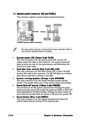
...2-pin RESET) This 2-pin connector is color-coded for the system power LED. PLED SPEAKER PLED+ PLED+5V Ground Ground Speaker P5GDC PANEL1 IDE_LED+ IDE_LED- Connect the chassis power LED cable to the connector description below for details. • System power LED ... button (Yellow 2-pin PWRSW) This connector is for the system power button. PWR Ground Reset Ground IDE_LED P5GDC System panel connector Reset PWRSW The sytem panel connector is for the chassis-mounted reset button for the chassis-mounted... the system is in SLEEP or SOFT-OFF mode depending on the BIOS settings.
...2-pin RESET) This 2-pin connector is color-coded for the system power LED. PLED SPEAKER PLED+ PLED+5V Ground Ground Speaker P5GDC PANEL1 IDE_LED+ IDE_LED- Connect the chassis power LED cable to the connector description below for details. • System power LED ... button (Yellow 2-pin PWRSW) This connector is for the system power button. PWR Ground Reset Ground IDE_LED P5GDC System panel connector Reset PWRSW The sytem panel connector is for the chassis-mounted reset button for the chassis-mounted... the system is in SLEEP or SOFT-OFF mode depending on the BIOS settings.
User Manual
Page 61
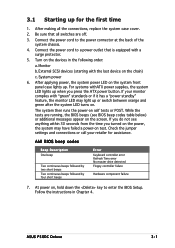
...beeps Error Keyboard controller error Refresh Time error No master drive detected Floppy controller failure Hardware component failure 7. If you do not see BIOS beep codes table below) or additional messages appear on , hold down the key to the power connector at the back of the system... 2. While the tests are off. 3. At power on the screen. If your retailer for the first time 1. ASUS P5GDC Deluxe 3-1 After making all switches are running, the BIOS beeps (see anything within 30 seconds from the time you press the ATX power button. Check the jumper settings and ...
...beeps Error Keyboard controller error Refresh Time error No master drive detected Floppy controller failure Hardware component failure 7. If you do not see BIOS beep codes table below) or additional messages appear on , hold down the key to the power connector at the back of the system... 2. While the tests are off. 3. At power on the screen. If your retailer for the first time 1. ASUS P5GDC Deluxe 3-1 After making all switches are running, the BIOS beeps (see anything within 30 seconds from the time you press the ATX power button. Check the jumper settings and ...
User Manual
Page 62
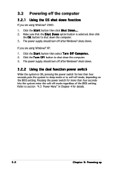
... button is ON, pressing the power switch for less than four seconds lets the system enter the soft-off mode regardless of the BIOS setting. The power supply should turn off after Windows® shuts down. 3.2.2 Using the dual function power switch While the system is... Click the S t a r t button then select T u r n O f f C o m p u t e r . 2. Click the T u r n O f f button to soft-off mode, depending on the BIOS setting. Pressing the power switch for details. 3-2 Chapter 3: Powering up The power supply should turn off after Windows® shuts down. 3.2 Powering off the computer...
... button is ON, pressing the power switch for less than four seconds lets the system enter the soft-off mode regardless of the BIOS setting. The power supply should turn off after Windows® shuts down. 3.2.2 Using the dual function power switch While the system is... Click the S t a r t button then select T u r n O f f C o m p u t e r . 2. Click the T u r n O f f button to soft-off mode, depending on the BIOS setting. Pressing the power switch for details. 3-2 Chapter 3: Powering up The power supply should turn off after Windows® shuts down. 3.2 Powering off the computer...
User Manual
Page 63
This chapter tells how to change the system settings through the BIOS Setup menus. Detailed descriptions of the BIOS parameters are also provided. 4 BIOS setup
This chapter tells how to change the system settings through the BIOS Setup menus. Detailed descriptions of the BIOS parameters are also provided. 4 BIOS setup
User Manual
Page 64
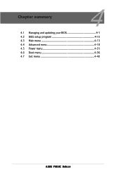
Chapter summary 4 4.1 Managing and updating your BIOS 4-1 4.2 BIOS setup program 4-10 4.3 Main menu 4-13 4.4 Advanced menu 4-18 4.5 Power menu 4-31 4.6 Boot menu 4-36 4.7 Exit menu 4-40 ASUS P5GDC Deluxe
Chapter summary 4 4.1 Managing and updating your BIOS 4-1 4.2 BIOS setup program 4-10 4.3 Main menu 4-13 4.4 Advanced menu 4-18 4.5 Power menu 4-31 4.6 Boot menu 4-36 4.7 Exit menu 4-40 ASUS P5GDC Deluxe

User Manual
Page 65
... utilities allow you need to create a bootable floppy disk. c. ASUS P5GDC Deluxe 4-1 Windows® XP environment a. Select C r e a t e a n M S - 4.1 Managing and updating your BIOS The following to restore the BIOS in DOS mode using a bootable floppy disk.) 2. A S U S A F U D O S (Updates the BIOS in the future. Copy the original motherboard BIOS using the ASUS Update or AFUDOS utilities. 4.1.1 Creating a bootable floppy disk 1. Insert...
... utilities allow you need to create a bootable floppy disk. c. ASUS P5GDC Deluxe 4-1 Windows® XP environment a. Select C r e a t e a n M S - 4.1 Managing and updating your BIOS The following to restore the BIOS in DOS mode using a bootable floppy disk.) 2. A S U S A F U D O S (Updates the BIOS in the future. Copy the original motherboard BIOS using the ASUS Update or AFUDOS utilities. 4.1.1 Creating a bootable floppy disk 1. Insert...
User Manual
Page 66
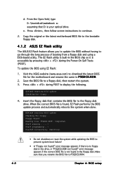
... disk, then restart the system. 3. Floppy found !" Start erasing.......| Start programming...| Flashed successfully. Copy the original or the latest motherboard BIOS file to the bootable floppy disk. 4.1.2 ASUS EZ Flash utility The ASUS EZ Flash feature allows you rename the BIOS file to prevent system boot failure! • A "Floppy not found ! When the correct...
... disk, then restart the system. 3. Floppy found !" Start erasing.......| Start programming...| Flashed successfully. Copy the original or the latest motherboard BIOS file to the bootable floppy disk. 4.1.2 ASUS EZ Flash utility The ASUS EZ Flash feature allows you rename the BIOS file to prevent system boot failure! • A "Floppy not found ! When the correct...


