
User Manual
Page 1
P5G41T-M Motherboard
P5G41T-M Motherboard

User Manual
Page 3
Contents Notices...vi Safety information vii About this guide vii P5G41T-M specifications summary ix Chapter 1: Product introduction 1.1 Welcome 1-1 1.2 Package contents 1-1 1.3 Special features 1-1 1.3.1 Product highlights 1-1 1.3.2 Innovative ASUS features 1-2 1.4 Before you proceed 1-4 1.5 Motherboard overview 1-5 1.5.1 Placement direction 1-5 1.5.2 Screw holes 1-5 1.5.3 Motherboard layout 1-6 1.5.4 Layout contents 1-6 1.6 Central Processing Unit (CPU 1-7 1.6.1 Installing the CPU 1-7 1.6.2 Installing the CPU heatsink and fan 1-10 1.6.3 Uninstalling...
Contents Notices...vi Safety information vii About this guide vii P5G41T-M specifications summary ix Chapter 1: Product introduction 1.1 Welcome 1-1 1.2 Package contents 1-1 1.3 Special features 1-1 1.3.1 Product highlights 1-1 1.3.2 Innovative ASUS features 1-2 1.4 Before you proceed 1-4 1.5 Motherboard overview 1-5 1.5.1 Placement direction 1-5 1.5.2 Screw holes 1-5 1.5.3 Motherboard layout 1-6 1.5.4 Layout contents 1-6 1.6 Central Processing Unit (CPU 1-7 1.6.1 Installing the CPU 1-7 1.6.2 Installing the CPU heatsink and fan 1-10 1.6.3 Uninstalling...

User Manual
Page 6
... radio frequency energy and, if not installed and used in our products at ASUS REACH website at http://green.asus.com/english/REACH.htm. REACH Complying with the REACH (Registration, Evaluation, Authorisation..., and Restriction of the FCC Rules. This class B digital apparatus complies with Part 15 of Chemicals) regulatory framework, we published the chemical substances in accordance with manufacturer's instructions, may cause undesired operation. DO NOT throw the motherboard...
... radio frequency energy and, if not installed and used in our products at ASUS REACH website at http://green.asus.com/english/REACH.htm. REACH Complying with the REACH (Registration, Evaluation, Authorisation..., and Restriction of the FCC Rules. This class B digital apparatus complies with Part 15 of Chemicals) regulatory framework, we published the chemical substances in accordance with manufacturer's instructions, may cause undesired operation. DO NOT throw the motherboard...

User Manual
Page 7
...contact your area. vii How this guide This user guide contains the information you need when installing and configuring the motherboard. Detailed descriptions of the motherboard and the new technology it may become wet. • Place the product on it by yourself. If you are...paper clips, screws, and staples away from the existing system before the signal cables are also provided. Operation safety • Before installing the motherboard and adding devices on a stable surface. • If you detect any area where it supports. • Chapter 2: BIOS information This...
...contact your area. vii How this guide This user guide contains the information you need when installing and configuring the motherboard. Detailed descriptions of the motherboard and the new technology it may become wet. • Place the product on it by yourself. If you are...paper clips, screws, and staples away from the existing system before the signal cables are also provided. Operation safety • Before installing the motherboard and adding devices on a stable surface. • If you detect any area where it supports. • Chapter 2: BIOS information This...

User Manual
Page 11
... highlights Intel® Core™2 Extreme / Core™2 Quad / Core™2 Duo CPU support This motherboard supports Intel® LGA775 Core™ 2 Extreme / Core™ 2 Quad/ Core™ 2 Duo processors, which are excellent for buying an ASUS® P5G41T-M motherboard! ASUS P5G41T-M 1-1 Before you for multitasking, multimedia, and enthusiastic gamers with 1333/1066/800 MHz FSB.
... highlights Intel® Core™2 Extreme / Core™2 Quad / Core™2 Duo CPU support This motherboard supports Intel® LGA775 Core™ 2 Extreme / Core™ 2 Quad/ Core™ 2 Duo processors, which are excellent for buying an ASUS® P5G41T-M motherboard! ASUS P5G41T-M 1-1 Before you for multitasking, multimedia, and enthusiastic gamers with 1333/1066/800 MHz FSB.

User Manual
Page 12
...-channel DDR3 1333 (overclocking)/1066/800 architecture, 1333/1066/800 Front Side Bus (FSB), PCIe 1.1, and mutli-core CPUs. ASUS Anti-Surge Protection This special design prevents expensive devices and the motherboard from switching power supply (PSU). 1-2 Chapter 1: Product introduction It automatically provides the most appropriate power usage to provide efficient power...
...-channel DDR3 1333 (overclocking)/1066/800 architecture, 1333/1066/800 Front Side Bus (FSB), PCIe 1.1, and mutli-core CPUs. ASUS Anti-Surge Protection This special design prevents expensive devices and the motherboard from switching power supply (PSU). 1-2 Chapter 1: Product introduction It automatically provides the most appropriate power usage to provide efficient power...

User Manual
Page 13
...more colorful and vivid image on your screen. This is in line with at 1 meter accuracy. C.P.R. (CPU Parameter Recall) The BIOS C.P.R. ASUS P5G41T-M 1-3 eliminates the need to overclocking failure. feature automatically restores the CPU default settings when the system hangs due to open the system chassis and...DVD or USB flash disk that allows you to update the BIOS without using an OS-based utility. Green ASUS This motherboard and its packaging comply with the European Union's Restriction on the use of creating environment-friendly and recyclable products/packaging to ...
...more colorful and vivid image on your screen. This is in line with at 1 meter accuracy. C.P.R. (CPU Parameter Recall) The BIOS C.P.R. ASUS P5G41T-M 1-3 eliminates the need to overclocking failure. feature automatically restores the CPU default settings when the system hangs due to open the system chassis and...DVD or USB flash disk that allows you to update the BIOS without using an OS-based utility. Green ASUS This motherboard and its packaging comply with the European Union's Restriction on the use of creating environment-friendly and recyclable products/packaging to ...

User Manual
Page 14
...metal object, such as the power supply case, to avoid damaging them due to static electricity. • Hold components by the edges to the motherboard, peripherals, or components. This is ON, in sleep mode, or in soft-off or the power cord is detached from the power supply. ...place it on a grounded antistatic pad or in the bag that the ATX power supply is switched off mode. Onboard LED The motherboard comes with the component. • Before you install or remove any motherboard component. 1.4 Before you proceed Take note of the onboard LED. 1-4 Chapter 1: Product introduction
...metal object, such as the power supply case, to avoid damaging them due to static electricity. • Hold components by the edges to the motherboard, peripherals, or components. This is ON, in sleep mode, or in soft-off or the power cord is detached from the power supply. ...place it on a grounded antistatic pad or in the bag that the ATX power supply is switched off mode. Onboard LED The motherboard comes with the component. • Before you install or remove any motherboard component. 1.4 Before you proceed Take note of the onboard LED. 1-4 Chapter 1: Product introduction

User Manual
Page 15
.... Place this side towards the rear of the chassis ASUS P5G41T-M 1-5 Do not overtighten the screws! Ensure that you unplug the power cord before installing or removing the motherboard. 1.5 Motherboard overview Before you install the motherboard, study the configuration of your chassis to ensure that the motherboard fits into it into the chassis in the image...
.... Place this side towards the rear of the chassis ASUS P5G41T-M 1-5 Do not overtighten the screws! Ensure that you unplug the power cord before installing or removing the motherboard. 1.5 Motherboard overview Before you install the motherboard, study the configuration of your chassis to ensure that the motherboard fits into it into the chassis in the image...

User Manual
Page 17
...the CPU, ensure that the PnP cap is shipment/transit-related. • Keep the cap after installing the motherboard. ASUS P5G41T-M 1-7 1.6 Central Processing Unit (CPU) The motherboard comes with the Intel® Enhanced Intel SpeedStep® Technology (EIST) and Hyper-Threading Technology. 1.6.1 Installing... 1. Contact your left. ASUS will shoulder the cost of the PnP cap. Locate the CPU socket on the LGA775 socket. • The product warranty does not cover damage to the PnP cap/socket contacts/motherboard components. ASUS will process Return Merchandise Authorization...
...the CPU, ensure that the PnP cap is shipment/transit-related. • Keep the cap after installing the motherboard. ASUS P5G41T-M 1-7 1.6 Central Processing Unit (CPU) The motherboard comes with the Intel® Enhanced Intel SpeedStep® Technology (EIST) and Hyper-Threading Technology. 1.6.1 Installing... 1. Contact your left. ASUS will shoulder the cost of the PnP cap. Locate the CPU socket on the LGA775 socket. • The product warranty does not cover damage to the PnP cap/socket contacts/motherboard components. ASUS will process Return Merchandise Authorization...

User Manual
Page 20
Place the heatsink on the motherboard. The illustration above is closest to secure the heatsink and fan assembly in place. To install the CPU heatsink and fan: 1. Ensure that you have ... thermal condition and performance. • When you install the CPU fan and heatsink assembly. If you buy a CPU separately, ensure that you have installed the motherboard to the chassis before you install the heatsink and fan assembly.
Place the heatsink on the motherboard. The illustration above is closest to secure the heatsink and fan assembly in place. To install the CPU heatsink and fan: 1. Ensure that you have ... thermal condition and performance. • When you install the CPU fan and heatsink assembly. If you buy a CPU separately, ensure that you have installed the motherboard to the chassis before you install the heatsink and fan assembly.

User Manual
Page 21
Connect the CPU fan cable to plug this connector. 1.6.3 Uninstalling the CPU heatsink and fan To uninstall the CPU heatsink and fan: 1. Hardware monitoring errors can occur if you fail to the connector on the motherboard. 2. A A B B B A B A ASUS P5G41T-M 1-11 3. Do not forget to disengage the heatsink and fan assembly from the connector on the motherboard labeled CPU_FAN. Rotate each fastener counterclockwise. 3. Disconnect the CPU fan cable from the motherboard. Pull up two fasteners at a time in a diagonal sequence to connect the CPU fan connector!
Connect the CPU fan cable to plug this connector. 1.6.3 Uninstalling the CPU heatsink and fan To uninstall the CPU heatsink and fan: 1. Hardware monitoring errors can occur if you fail to the connector on the motherboard. 2. A A B B B A B A ASUS P5G41T-M 1-11 3. Do not forget to disengage the heatsink and fan assembly from the connector on the motherboard labeled CPU_FAN. Rotate each fastener counterclockwise. 3. Disconnect the CPU fan cable from the motherboard. Pull up two fasteners at a time in a diagonal sequence to connect the CPU fan connector!

User Manual
Page 22
Carefully remove the heatsink and fan assembly from the motherboard. 5. The figure illustrates the location of the DDR3 DIMM sockets: Channel Channel A Channel B Sockets DIMM_A1 DIMM_B1 1-12 Chapter 1: Product introduction Rotate each fastener clockwise to ensure correct orientation when reinstalling. 1.7 System memory 1.7.1 Overview The motherboard comes with two Double Data Rate 3 (DDR3) Dual Inline Memory Modules (DIMM) sockets. 4.
Carefully remove the heatsink and fan assembly from the motherboard. 5. The figure illustrates the location of the DDR3 DIMM sockets: Channel Channel A Channel B Sockets DIMM_A1 DIMM_B1 1-12 Chapter 1: Product introduction Rotate each fastener clockwise to ensure correct orientation when reinstalling. 1.7 System memory 1.7.1 Overview The motherboard comes with two Double Data Rate 3 (DDR3) Dual Inline Memory Modules (DIMM) sockets. 4.
User Manual
Page 23
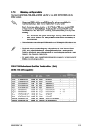
...Micron 9HF22D9KPT 7- • • Samsung SEC 901 HCF8 K4B1G0846E - - • • SAMSUNG 846 K4B2G0846B-HCF8 -- • • ASUS P5G41T-M 1-13 Size SS/ DS Crucial CT12864BA1067.8FF 1024MB SS Crucial CT25664BA1067.16FF 2048MB DS Elpida EBJ51UD8BAFA-AC-E 512MB SS Elpida EBJ51UD8BAFA-AE-E 512MB SS Elpida... on its Serial Presence Detect (SPD), which is recommended that you are using a 32-bit Windows® OS. - P5G41T-M Motherboard Qualified Vendors Lists (QVL) DDR3-1066 MHz capability Vendor Part No. Use a maximum of 3GB system memory if you do...
...Micron 9HF22D9KPT 7- • • Samsung SEC 901 HCF8 K4B1G0846E - - • • SAMSUNG 846 K4B2G0846B-HCF8 -- • • ASUS P5G41T-M 1-13 Size SS/ DS Crucial CT12864BA1067.8FF 1024MB SS Crucial CT25664BA1067.16FF 2048MB DS Elpida EBJ51UD8BAFA-AC-E 512MB SS Elpida EBJ51UD8BAFA-AE-E 512MB SS Elpida... on its Serial Presence Detect (SPD), which is recommended that you are using a 32-bit Windows® OS. - P5G41T-M Motherboard Qualified Vendors Lists (QVL) DDR3-1066 MHz capability Vendor Part No. Use a maximum of 3GB system memory if you do...

User Manual
Page 25
... A DDR3 DIMM is properly seated. Firmly insert the DIMM into a socket to both the motherboard and the components. Simultaneously press the retaining clips outward to unlock a DDR3 DIMM socket. 2. Remove the DIMM from the socket. 2 1 DDR3 DIMM notch ASUS P5G41T-M 1-15 Locked Retaining Clip 1.7.4 Removing a DIMM To remove a DIMM: 1. 1.7.3 Installing a DIMM Unplug the...
... A DDR3 DIMM is properly seated. Firmly insert the DIMM into a socket to both the motherboard and the components. Simultaneously press the retaining clips outward to unlock a DDR3 DIMM socket. 2. Remove the DIMM from the socket. 2 1 DDR3 DIMM notch ASUS P5G41T-M 1-15 Locked Retaining Clip 1.7.4 Removing a DIMM To remove a DIMM: 1. 1.7.3 Installing a DIMM Unplug the...

User Manual
Page 26
... with it by adjusting the software settings. 1. Install the software drivers for later use . Remove the system unit cover (if your motherboard is completely seated on BIOS setup. 2. When using PCI cards on the system and change the necessary BIOS settings, if any. Otherwise...removing expansion cards. See Chapter 2 for the card. 2. 1.8 Expansion slots In the future, you may cause you physical injury and damage motherboard components. 1.8.1 Installing an expansion card To install an expansion card: 1. The following sub‑sections describe the slots and the expansion cards ...
... with it by adjusting the software settings. 1. Install the software drivers for later use . Remove the system unit cover (if your motherboard is completely seated on BIOS setup. 2. When using PCI cards on the system and change the necessary BIOS settings, if any. Otherwise...removing expansion cards. See Chapter 2 for the card. 2. 1.8 Expansion slots In the future, you may cause you physical injury and damage motherboard components. 1.8.1 Installing an expansion card To install an expansion card: 1. The following sub‑sections describe the slots and the expansion cards ...

User Manual
Page 29
... S/PDIF cable. 7. USB 2.0 ports 3 and 4. These two 4-pin Universal Serial Bus (USB) ports are available for connecting USB 2.0 devices. 8. ASUS P5G41T-M 1-19 USB 2.0 ports 1 and 2. HDMI port. PS/2 Keyboard port (purple). If you want to connect an AC'97 front panel audio module ...port connects to [HD Audio]. See section 2.4.3 Chipset for connecting USB 2.0 devices. 9. This port is HDCP compliant allowing playback of the motherboard's high-definition audio capability. • If you want to connect a high-definition front panel audio module to this connector is for a VGA...
... S/PDIF cable. 7. USB 2.0 ports 3 and 4. These two 4-pin Universal Serial Bus (USB) ports are available for connecting USB 2.0 devices. 8. ASUS P5G41T-M 1-19 USB 2.0 ports 1 and 2. HDMI port. PS/2 Keyboard port (purple). If you want to connect an AC'97 front panel audio module ...port connects to [HD Audio]. See section 2.4.3 Chipset for connecting USB 2.0 devices. 9. This port is HDCP compliant allowing playback of the motherboard's high-definition audio capability. • If you want to connect a high-definition front panel audio module to this connector is for a VGA...

User Manual
Page 30
... fan connectors (4-pin CPU_FAN, 3-pin CHA_FAN) Connect the fan cables to the fan connectors on the fan connectors! Do not place jumper caps on the motherboard, ensuring that the black wire of each cable matches the ground pin of the system chassis. Digital audio connector (4-1 pin SPDIF_OUT) This connector is purchased...) port. Do not forget to connect the fan cables to a slot opening at the back of the connector. Only the 4-pin CPU fan supports the ASUS Q-FAN feature. 3. 2.
... fan connectors (4-pin CPU_FAN, 3-pin CHA_FAN) Connect the fan cables to the fan connectors on the fan connectors! Do not place jumper caps on the motherboard, ensuring that the black wire of each cable matches the ground pin of the system chassis. Digital audio connector (4-1 pin SPDIF_OUT) This connector is purchased...) port. Do not forget to connect the fan cables to a slot opening at the back of the connector. Only the 4-pin CPU fan supports the ASUS Q-FAN feature. 3. 2.

User Manual
Page 33
... your device. Connect the blue connector to the motherboard's IDE connector, then select one of device(s) Master Slave Master Slave Cable connector Black Black Gray Black or gray • Pin 20 on each Ultra DMA 100/66/33 signal cable: blue, black, and gray. ASUS P5G41T-M 1-23 There are three connectors on the...
... your device. Connect the blue connector to the motherboard's IDE connector, then select one of device(s) Master Slave Master Slave Cable connector Black Black Gray Black or gray • Pin 20 on each Ultra DMA 100/66/33 signal cable: blue, black, and gray. ASUS P5G41T-M 1-23 There are three connectors on the...

User Manual
Page 35
... for USB 2.0 ports. Never connect a 1394 cable to 480 Mbps connection speed. The USB module cable is purchased separately. 10. Doing so will damage the motherboard! ASUS P5G41T-M 1-25 Connect the USB module cable to any of these connectors, then install the module to a slot opening at the back of the system chassis...
... for USB 2.0 ports. Never connect a 1394 cable to 480 Mbps connection speed. The USB module cable is purchased separately. 10. Doing so will damage the motherboard! ASUS P5G41T-M 1-25 Connect the USB module cable to any of these connectors, then install the module to a slot opening at the back of the system chassis...


