
User Manual
Page 4
... items 2-6 2.2.6 Configuration fields 2-6 2.2.7 Pop-up window 2-6 2.2.8 Scroll bar 2-6 2.2.9 General help 2-6 2.3 Main menu 2-7 2.3.1 System Time 2-7 2.3.2 System Date 2-7 2.3.3 Primary IDE Master/Slave, SATA1~4 2-7 2.3.4 Storage Configuration 2-8 2.3.5 System Information 2-9 2.4 Advanced menu 2-9 2.4.1 JumperFree Configuration 2-9 2.4.2 CPU Configuration 2-11 2.4.3 Chipset 2-12 2.4.4 Onboard Devices Configuration 2-13 2.4.5 USB Configuration 2-14 2.4.6 PCI PnP 2-15 2.5 Power menu 2-15 2.5.1 Suspend Mode 2-15 2.5.2 ACPI 2.0 Support 2-15 2.5.3 ACPI APIC Support 2-15 iv
... items 2-6 2.2.6 Configuration fields 2-6 2.2.7 Pop-up window 2-6 2.2.8 Scroll bar 2-6 2.2.9 General help 2-6 2.3 Main menu 2-7 2.3.1 System Time 2-7 2.3.2 System Date 2-7 2.3.3 Primary IDE Master/Slave, SATA1~4 2-7 2.3.4 Storage Configuration 2-8 2.3.5 System Information 2-9 2.4 Advanced menu 2-9 2.4.1 JumperFree Configuration 2-9 2.4.2 CPU Configuration 2-11 2.4.3 Chipset 2-12 2.4.4 Onboard Devices Configuration 2-13 2.4.5 USB Configuration 2-14 2.4.6 PCI PnP 2-15 2.5 Power menu 2-15 2.5.1 Suspend Mode 2-15 2.5.2 ACPI 2.0 Support 2-15 2.5.3 ACPI APIC Support 2-15 iv

User Manual
Page 10
...x USB 2.0/1.1 connectors support additional 4 USB 2.0/1.1 ports 1 x IDE connector 4 x Serial ATA connectors 1 x Front panel audio connector 1 x System panel connector 1 x S/PDIF Out connector 1 x LPT connector 1 x COM connector 1 x CPU fan connector 1 x Chassis fan connector 1 x 24-pin EATX power connector 1 x 4-pin ATX 12V power connector 8Mb Flash ROM, AMI BIOS, PnP, DMI 2.0, WfM 2.0, ACPI 2.0a, SM BIOS 2.5 WOL, PXE, WOR by Ring, PME Wake up 1 x Ultra DMA 100/66/33 cable 2 x Serial ATA cables 1 x I/O shield 1 x User Manual Drivers ASUS PC Probe II ASUS Update Anti-Virus software (OEM version...
...x USB 2.0/1.1 connectors support additional 4 USB 2.0/1.1 ports 1 x IDE connector 4 x Serial ATA connectors 1 x Front panel audio connector 1 x System panel connector 1 x S/PDIF Out connector 1 x LPT connector 1 x COM connector 1 x CPU fan connector 1 x Chassis fan connector 1 x 24-pin EATX power connector 1 x 4-pin ATX 12V power connector 8Mb Flash ROM, AMI BIOS, PnP, DMI 2.0, WfM 2.0, ACPI 2.0a, SM BIOS 2.5 WOL, PXE, WOR by Ring, PME Wake up 1 x Ultra DMA 100/66/33 cable 2 x Serial ATA cables 1 x I/O shield 1 x User Manual Drivers ASUS PC Probe II ASUS Update Anti-Virus software (OEM version...

User Manual
Page 12
... motherboard supports hard drives based on the Serial ATA (SATA) 3Gb/s storage specifications, delivering enhanced scalability and doubling the bus bandwidth for 3D graphics and other memory-demanding applications. Gigabit LAN solution The onboard LAN controller is enhanced with minimal noise. Dual channel DDR3 1333 (O.C.)/1066/800 support This motherboard supports DDR3 memory that features data transfer rates of the memory accesses. After you to provide efficient power management for advanced operating systems. Innovative ASUS...
... motherboard supports hard drives based on the Serial ATA (SATA) 3Gb/s storage specifications, delivering enhanced scalability and doubling the bus bandwidth for 3D graphics and other memory-demanding applications. Gigabit LAN solution The onboard LAN controller is enhanced with minimal noise. Dual channel DDR3 1333 (O.C.)/1066/800 support This motherboard supports DDR3 memory that features data transfer rates of the memory accesses. After you to provide efficient power management for advanced operating systems. Innovative ASUS...

User Manual
Page 13
ASUS Express Gate Express Gate is an auto-recovery tool that allows you to restore a corrupted BIOS file using the bundled support DVD or USB flash disk that allows you to update the BIOS without using an OS-based utility. When installing it on USB HDDs or flash drives, connect the drives to the motherboard USB port before entering the Windows® OS. • ASUS Express Gate supports installation on SATA HDDs, USB HDDs and flash drives with at 1 meter accuracy. ASUS CrashFree BIOS 3 ASUS CrashFree BIOS 3 is an ASUS exclusive OS, which lets you...
ASUS Express Gate Express Gate is an auto-recovery tool that allows you to restore a corrupted BIOS file using the bundled support DVD or USB flash disk that allows you to update the BIOS without using an OS-based utility. When installing it on USB HDDs or flash drives, connect the drives to the motherboard USB port before entering the Windows® OS. • ASUS Express Gate supports installation on SATA HDDs, USB HDDs and flash drives with at 1 meter accuracy. ASUS CrashFree BIOS 3 ASUS CrashFree BIOS 3 is an ASUS exclusive OS, which lets you...
User Manual
Page 23
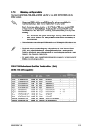
... megabits (Mb) chips or less. • The default memory operation frequency is dependent on the motherboard, the actual usable memory for overclocking may install 512MB, 1GB, 2GB, and 4GB unbuffered non‑ECC DDR3 DIMMs into the DIMM sockets. • Always install DIMMs with the same CAS latency. Install a 64-bit Windows® OS when you are using a 32-bit Windows® OS. - DIMM socket CL Voltage support (Optional) A* B* Micron...
... megabits (Mb) chips or less. • The default memory operation frequency is dependent on the motherboard, the actual usable memory for overclocking may install 512MB, 1GB, 2GB, and 4GB unbuffered non‑ECC DDR3 DIMMs into the DIMM sockets. • Always install DIMMs with the same CAS latency. Install a 64-bit Windows® OS when you are using a 32-bit Windows® OS. - DIMM socket CL Voltage support (Optional) A* B* Micron...

User Manual
Page 26
... BIOS setup. 2. Replace the system cover. 1.8.2 Configuring an expansion card After installing the expansion card, configure it and make the necessary hardware settings for information on the slot. 5. Assign an IRQ to the card. 3. Otherwise, conflicts will arise between the two PCI groups, making the system unstable and the card inoperable. 1.8.3 PCI slots The PCI slots support cards such as a LAN card, SCSI card, USB card, and other cards that comply with PCI specifications. 1.8.4 PCI Express x1 slot This motherboard supports PCI Express x1 network cards...
... BIOS setup. 2. Replace the system cover. 1.8.2 Configuring an expansion card After installing the expansion card, configure it and make the necessary hardware settings for information on the slot. 5. Assign an IRQ to the card. 3. Otherwise, conflicts will arise between the two PCI groups, making the system unstable and the card inoperable. 1.8.3 PCI slots The PCI slots support cards such as a LAN card, SCSI card, USB card, and other cards that comply with PCI specifications. 1.8.4 PCI Express x1 slot This motherboard supports PCI Express x1 network cards...

User Manual
Page 36
... following screen is NOT enabled in your OS documentation for detailed information. • Ensure that you install Windows® XP Service Pack 3 or later version / Windows® Vista Service Pack 1 or later version before installing the drivers for better compatibility and system stability. 1.11.2 Support DVD information The Support DVD that comes with the motherboard package contains the drivers, software applications, and utilities that you can install to change at www.asus.com...
... following screen is NOT enabled in your OS documentation for detailed information. • Ensure that you install Windows® XP Service Pack 3 or later version / Windows® Vista Service Pack 1 or later version before installing the drivers for better compatibility and system stability. 1.11.2 Support DVD information The Support DVD that comes with the motherboard package contains the drivers, software applications, and utilities that you can install to change at www.asus.com...

User Manual
Page 37
... Drivers menu appears. 2. Click the Utilities tab, then click ASUS Update. 3. b. ASUS P5G41T-M 2-1 Updating the BIOS To update the BIOS: 1. From the dropdown list, select any of the original motherboard BIOS file to a USB flash disk in case you need to manage, save, and update the motherboard BIOS in Windows® environment. • ASUS Update requires an Internet connection either through a network or an Internet Service Provider (ISP). • This utility is available in the optical drive. Installing ASUS Update To install ASUS Update: 1. Place the support DVD...
... Drivers menu appears. 2. Click the Utilities tab, then click ASUS Update. 3. b. ASUS P5G41T-M 2-1 Updating the BIOS To update the BIOS: 1. From the dropdown list, select any of the original motherboard BIOS file to a USB flash disk in case you need to manage, save, and update the motherboard BIOS in Windows® environment. • ASUS Update requires an Internet connection either through a network or an Internet Service Provider (ISP). • This utility is available in the optical drive. Installing ASUS Update To install ASUS Update: 1. Place the support DVD...

User Manual
Page 38
... Open window, then click Open. 3. Follow the onscreen instructions to prevent system boot failure! 2-2 Chapter 2: BIOS information Insert the USB flash disk that contains the latest BIOS file to update the BIOS without using EZ Flash 2: 1. Before you to the USB port, then launch EZ Flash 2 in any of updating itself through the Internet. The ASUS Update utility is capable of these two ways: • Press + during POST. • Enter the BIOS setup program. Select Update BIOS...
... Open window, then click Open. 3. Follow the onscreen instructions to prevent system boot failure! 2-2 Chapter 2: BIOS information Insert the USB flash disk that contains the latest BIOS file to update the BIOS without using EZ Flash 2: 1. Before you to the USB port, then launch EZ Flash 2 in any of updating itself through the Internet. The ASUS Update utility is capable of these two ways: • Press + during POST. • Enter the BIOS setup program. Select Update BIOS...

User Manual
Page 39
... removable device that contains the BIOS file to the USB port or to section 2.8 Exit menu for the BIOS file. When found, the utility reads the BIOS file and starts flashing the corrupted BIOS file. 4. ASUS P5G41T-M 2-3 Select the Load Setup Defaults item under the Exit menu. Refer to the floppy disk drive, if supported. 3. Ensure to load the BIOS default settings to restore the BIOS file when it fails or gets corrupted during the updating process. For motherboards without the floppy connector, prepare a USB flash disk before using this utility. Turn...
... removable device that contains the BIOS file to the USB port or to section 2.8 Exit menu for the BIOS file. When found, the utility reads the BIOS file and starts flashing the corrupted BIOS file. 4. ASUS P5G41T-M 2-3 Select the Load Setup Defaults item under the Exit menu. Refer to the floppy disk drive, if supported. 3. Ensure to load the BIOS default settings to restore the BIOS file when it fails or gets corrupted during the updating process. For motherboards without the floppy connector, prepare a USB flash disk before using this utility. Turn...

User Manual
Page 42
...Pop-up window Select a menu item then press to display a pop-up window screen. 2.2.3 Navigation keys At the bottom right corner of a menu screen are items that do not fit on the Pop-up window with the configuration options for that item. Use the navigation keys to display a list of options. Use [+] or [-] to select a field. configurable, you can change the settings. Main Advanced BIOS SETUP UTILITY Power Boot Tools Exit Suspend Mode ACPI 2.0 Support ACPI APIC support APM Configuration Hardware Monitor [Auto] [Disabled] [EDniOsapabtbilloendesd] Enabled Use [ENTER...
...Pop-up window Select a menu item then press to display a pop-up window screen. 2.2.3 Navigation keys At the bottom right corner of a menu screen are items that do not fit on the Pop-up window with the configuration options for that item. Use the navigation keys to display a list of options. Use [+] or [-] to select a field. configurable, you can change the settings. Main Advanced BIOS SETUP UTILITY Power Boot Tools Exit Suspend Mode ACPI 2.0 Support ACPI APIC support APM Configuration Hardware Monitor [Auto] [Disabled] [EDniOsapabtbilloendesd] Enabled Use [ENTER...

User Manual
Page 43
... Mode, Async DMA, Ultra DMA, and SMART monitoring). Select ARMD (ATAPI Removable Media Device) if your device is installed in the system. ASUS P5G41T-M 2-7 Storage Configuration System Information Select Screen Select Item +- Select a device item then press to navigate through them. Select CDROM if you are not user-configurable. Refer to section 2.2.1 BIOS menu screen for each IDE/SATA device. 2.3 Main menu When you enter the BIOS Setup program, the Main menu screen appears, giving you select the SATA 1/2/3/4 devices. Main Advanced BIOS SETUP UTILITY Power Boot...
... Mode, Async DMA, Ultra DMA, and SMART monitoring). Select ARMD (ATAPI Removable Media Device) if your device is installed in the system. ASUS P5G41T-M 2-7 Storage Configuration System Information Select Screen Select Item +- Select a device item then press to navigate through them. Select CDROM if you are not user-configurable. Refer to section 2.2.1 BIOS menu screen for each IDE/SATA device. 2.3 Main menu When you enter the BIOS Setup program, the Main menu screen appears, giving you select the SATA 1/2/3/4 devices. Main Advanced BIOS SETUP UTILITY Power Boot...

User Manual
Page 44
... change the configurations for detecting ATA/ATAPI devices. IDE Detect Time Out (Sec) [35] Selects the time out value for the SATA devices installed in the system. Configuration options: [Disabled] [Auto] PIO Mode [Auto] Selects the PIO mode. Select an item then press if you to configure the item. Configuration options: [Disabled] [Compatible] [Enhanced] Enhanced Mode Support On [S-ATA] Sets Serial ATA, Parallel ATA or both as native mode. Configuration options: [Auto] [Disabled] [Enabled] 32Bit Data Transfer [Enabled] Enables or disables 32-bit...
... change the configurations for detecting ATA/ATAPI devices. IDE Detect Time Out (Sec) [35] Selects the time out value for the SATA devices installed in the system. Configuration options: [Disabled] [Auto] PIO Mode [Auto] Selects the PIO mode. Select an item then press if you to configure the item. Configuration options: [Disabled] [Compatible] [Enhanced] Enhanced Mode Support On [S-ATA] Sets Serial ATA, Parallel ATA or both as native mode. Configuration options: [Auto] [Disabled] [Enabled] 32Bit Data Transfer [Enabled] Enables or disables 32-bit...

User Manual
Page 45
... the preset overclocking configuration options: Manual - Processor Displays the auto-detected CPU specification. Main Advanced Power BIOS SETUP UTILITY Boot Tools Exit JumperFree Configuration CPU Configuration Chipset Onboard Devices Configuration USB Configuration PCIPnP Adjust System frequency/voltage. 2.4.1 JumperFree Configuration The items in this menu allows you to change the settings for the CPU and other system devices. loads the optimal settings for stability when overclocking. 2.3.5 System Information This menu gives you to individually set overclocking parameters...
... the preset overclocking configuration options: Manual - Processor Displays the auto-detected CPU specification. Main Advanced Power BIOS SETUP UTILITY Boot Tools Exit JumperFree Configuration CPU Configuration Chipset Onboard Devices Configuration USB Configuration PCIPnP Adjust System frequency/voltage. 2.4.1 JumperFree Configuration The items in this menu allows you to change the settings for the CPU and other system devices. loads the optimal settings for stability when overclocking. 2.3.5 System Information This menu gives you to individually set overclocking parameters...
User Manual
Page 48
...the graphics controller as multiple virtual systems. Configuration options: [Enabled] [Disabled] CPU TM Function [Enabled] Enables or disables Intel® CPU Thermal Monitor (TM) function, a CPU overheating protection function. Configuration options: [IGD] [PCI/IGD] [PCI/PEG] [PEG/IGD] [PEG/PCI] IGD Graphics Mode Select [Enabled, 32MB] Allows you to enable or disable configurating DRAM Timing by the Interanal graphics device. Setting this item to [Disabled] if you to change the advanced chipset settings. North Bridge Configuration Memory Remap Feature [Enabled] Allows...
...the graphics controller as multiple virtual systems. Configuration options: [Enabled] [Disabled] CPU TM Function [Enabled] Enables or disables Intel® CPU Thermal Monitor (TM) function, a CPU overheating protection function. Configuration options: [IGD] [PCI/IGD] [PCI/PEG] [PEG/IGD] [PEG/PCI] IGD Graphics Mode Select [Enabled, 32MB] Allows you to enable or disable configurating DRAM Timing by the Interanal graphics device. Setting this item to [Disabled] if you to change the advanced chipset settings. North Bridge Configuration Memory Remap Feature [Enabled] Allows...

User Manual
Page 49
...or disable the onboard Gigabit LAN controller. This item appears only when the Onboard LAN item is not user- GTT Graphics Memory Size [No VT mode, 2MB] This item is set this item to Enabled. If High Definition Audio Front Panel used, set to [HD Audio] mode. Configuration options: [Enabled] [Disabled] Onboard LAN Boot ROM [Disabled] Allows you to select the Protected Audio-Video Path (PAVP) mode. configurable. Configuration options: [AC97] [HD Audio] 2.4.4 Onboard Devices Configuration Onboard Gigabit LAN [Enabled] Allows you to select the Parallel Port mode. Configuration options...
...or disable the onboard Gigabit LAN controller. This item appears only when the Onboard LAN item is not user- GTT Graphics Memory Size [No VT mode, 2MB] This item is set this item to Enabled. If High Definition Audio Front Panel used, set to [HD Audio] mode. Configuration options: [Enabled] [Disabled] Onboard LAN Boot ROM [Disabled] Allows you to select the Protected Audio-Video Path (PAVP) mode. configurable. Configuration options: [AC97] [HD Audio] 2.4.4 Onboard Devices Configuration Onboard Gigabit LAN [Enabled] Allows you to select the Parallel Port mode. Configuration options...
User Manual
Page 50
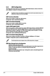
..., the USB controller legacy mode is plugged. Configuration options: [Disabled] [Enabled] USB 2.0 Controller [Enabled] Allows you to set the maximum time that the BIOS waits for Legacy USB storage devices, including USB flash drives and USB hard drives. Configuration options: [10 Sec] [20 Sec] [30 Sec] [40 Sec] Emulation Type [Auto] Allows you to disable or enable the USB functions. USB Mass Storage Device Configuration USB Mass Storage Reset Delay [20 Sec] Allows you to change the USB-related features. Configuration options: [Enabled] [Disabled] Legacy USB Support [Auto] Allows...
..., the USB controller legacy mode is plugged. Configuration options: [Disabled] [Enabled] USB 2.0 Controller [Enabled] Allows you to set the maximum time that the BIOS waits for Legacy USB storage devices, including USB flash drives and USB hard drives. Configuration options: [10 Sec] [20 Sec] [30 Sec] [40 Sec] Emulation Type [Auto] Allows you to disable or enable the USB functions. USB Mass Storage Device Configuration USB Mass Storage Reset Delay [20 Sec] Allows you to change the USB-related features. Configuration options: [Enabled] [Disabled] Legacy USB Support [Auto] Allows...

User Manual
Page 51
Plug and Play O/S [No] When set to display the configuration options. Main Advanced Power BIOS SETUP UTILITY Boot Tools Exit Suspend Mode ACPI 2.0 Support ACPI APIC Support Anti Surge Support [Auto] [Enabled] [Enabled] [Enabled] APM Configuration Hardware Monitor Select the ACPI state used for System Suspend. 2.5.1 Suspend Mode [Auto] Allows you to select the Advanced Configuration and Power Interface (ACPI) state to be used for boot. When set to malfunction. Select an item then press to [No], BIOS configures all the devices in the system. When set to...
Plug and Play O/S [No] When set to display the configuration options. Main Advanced Power BIOS SETUP UTILITY Boot Tools Exit Suspend Mode ACPI 2.0 Support ACPI APIC Support Anti Surge Support [Auto] [Enabled] [Enabled] [Enabled] APM Configuration Hardware Monitor Select the ACPI state used for System Suspend. 2.5.1 Suspend Mode [Auto] Allows you to select the Advanced Configuration and Power Interface (ACPI) state to be used for boot. When set to malfunction. Select an item then press to [No], BIOS configures all the devices in the system. When set to...

User Manual
Page 54
... ROM Display Mode [Force BIOS] Sets the display mode for information on top of the screen shows the default Not Installed. In the password box, key in setting a supervisor password. Configuration options: [Off] [On] Wait For 'F1' If Error [Enabled] When set or change the supervisor password. To clear the supervisor password, select the Change Supervisor Password then press twice. To change the system security settings. Configuration options: [Disabled] [Enabled] Set this item shows Installed. To set a password, this item to [Enabled] to change the supervisor password...
... ROM Display Mode [Force BIOS] Sets the display mode for information on top of the screen shows the default Not Installed. In the password box, key in setting a supervisor password. Configuration options: [Off] [On] Wait For 'F1' If Error [Enabled] When set or change the supervisor password. To clear the supervisor password, select the Change Supervisor Password then press twice. To change the system security settings. Configuration options: [Disabled] [Enabled] Set this item shows Installed. To set a password, this item to [Enabled] to change the supervisor password...
User Manual
Page 56
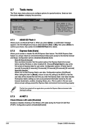
... utility to display the sub-menu. Configuration options: [No] [Reset] When setting this item to [Reset], ensure to save the setting to run ASUS EZ Flash 2. Configuration options: [Disabled] [Enabled] 2-20 Chapter 2: BIOS information Main Advanced Power BIOS SETUP UTILITY Boot Tools Exit ASUS EZ Flash 2 Express Gate Enter OS Timer Reset User Data AI NET 2 [Auto] [10 Seconds] [No] Press ENTER to run again when you to the BIOS so that the system waits at the first screen of the Atheros LAN cable...
... utility to display the sub-menu. Configuration options: [No] [Reset] When setting this item to [Reset], ensure to save the setting to run ASUS EZ Flash 2. Configuration options: [Disabled] [Enabled] 2-20 Chapter 2: BIOS information Main Advanced Power BIOS SETUP UTILITY Boot Tools Exit ASUS EZ Flash 2 Express Gate Enter OS Timer Reset User Data AI NET 2 [Auto] [10 Seconds] [No] Press ENTER to run again when you to the BIOS so that the system waits at the first screen of the Atheros LAN cable...


