
User Manual
Page 3
Contents Notices...vi Safety information vii About this guide vii P5G41T-M/USB3 specifications summary ix Chapter 1: Product introduction 1.1 Welcome 1-1 1.2 Package contents 1-1 1.3 Special features 1-1 1.3.1 Product highlights 1-1 1.3.2 Innovative ASUS features 1-3 1.4 Before you proceed 1-5 1.5 Motherboard overview 1-6 1.5.1 Placement direction 1-6 1.5.2 Screw holes 1-6 1.5.3 Motherboard layout 1-7 1.5.4 Layout contents... x1 slot 1-17 1.8.5 PCI Express x16 slot 1-17 1.9 Jumpers 1-18 1.10 Connectors 1-19 1.10.1 Rear panel connectors 1-19 1.10.2 Internal connectors 1-20 iii
Contents Notices...vi Safety information vii About this guide vii P5G41T-M/USB3 specifications summary ix Chapter 1: Product introduction 1.1 Welcome 1-1 1.2 Package contents 1-1 1.3 Special features 1-1 1.3.1 Product highlights 1-1 1.3.2 Innovative ASUS features 1-3 1.4 Before you proceed 1-5 1.5 Motherboard overview 1-6 1.5.1 Placement direction 1-6 1.5.2 Screw holes 1-6 1.5.3 Motherboard layout 1-7 1.5.4 Layout contents... x1 slot 1-17 1.8.5 PCI Express x16 slot 1-17 1.9 Jumpers 1-18 1.10 Connectors 1-19 1.10.1 Rear panel connectors 1-19 1.10.2 Internal connectors 1-20 iii
User Manual
Page 7
... are unplugged. • Seek professional assistance before using , contact your dealer immediately. • To avoid short circuits, keep paper clips, screws, and staples away from connectors, slots, sockets and circuitry. • Avoid dust, humidity, and temperature extremes. If you encounter technical problems with the package. • Before using the product, ensure...
... are unplugged. • Seek professional assistance before using , contact your dealer immediately. • To avoid short circuits, keep paper clips, screws, and staples away from connectors, slots, sockets and circuitry. • Avoid dust, humidity, and temperature extremes. If you encounter technical problems with the package. • Before using the product, ensure...
User Manual
Page 9
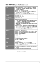
...10 1 x PCIe x16 slot 1 x PCIe x1 slot 2 x PCI slots 1 x Ultra DMA 100/66/33 connector 4 x Serial ATA 3Gb/s ports PCIe Gigabit LAN ALC887 High Definition Audio 8-channel CODEC * Use the chassis with max... you install a total memory of 1920 x 1080 (@ 60Hz) Supports RGB with max. P5G41T-M/USB3 specifications summary CPU Chipset Front Side Bus Memory Graphics Expansion slots Storage LAN Audio USB LGA775 socket...174; Hyper-Threading Technology and Enhanced Intel SpeedStep® Technology (EIST) * Refer to www.asus.com for the latest Memory QVL (Qualified Vendors Lists). ** When you are using a ...
...10 1 x PCIe x16 slot 1 x PCIe x1 slot 2 x PCI slots 1 x Ultra DMA 100/66/33 connector 4 x Serial ATA 3Gb/s ports PCIe Gigabit LAN ALC887 High Definition Audio 8-channel CODEC * Use the chassis with max... you install a total memory of 1920 x 1080 (@ 60Hz) Supports RGB with max. P5G41T-M/USB3 specifications summary CPU Chipset Front Side Bus Memory Graphics Expansion slots Storage LAN Audio USB LGA775 socket...174; Hyper-Threading Technology and Enhanced Intel SpeedStep® Technology (EIST) * Refer to www.asus.com for the latest Memory QVL (Qualified Vendors Lists). ** When you are using a ...
User Manual
Page 10
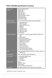
P5G41T-M/USB3 specifications summary ASUS unique features Special features Back panel I/O ports Internal connectors BIOS Manageability Accessories Support DVD Form factor ASUS CrashFree BIOS 3 ASUS AI NET 2 ASUS Q-Fan ASUS EZ Flash 2 ASUS MyLogo 2 ASUS Anti-Surge Protection ASUS Turbo Key ASUS Express Gate ASUS EPU-4 Engine 100% All High-quality Conductive Polymer Capacitors 1 x PS/2 keyboard port 1 x PS/2 mouse port 1 x Optical S/PDIF Out port...
P5G41T-M/USB3 specifications summary ASUS unique features Special features Back panel I/O ports Internal connectors BIOS Manageability Accessories Support DVD Form factor ASUS CrashFree BIOS 3 ASUS AI NET 2 ASUS Q-Fan ASUS EZ Flash 2 ASUS MyLogo 2 ASUS Anti-Surge Protection ASUS Turbo Key ASUS Express Gate ASUS EPU-4 Engine 100% All High-quality Conductive Polymer Capacitors 1 x PS/2 keyboard port 1 x PS/2 mouse port 1 x Optical S/PDIF Out port...
User Manual
Page 17
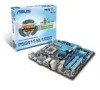
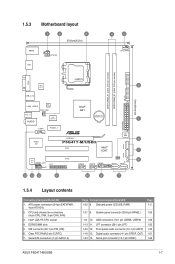
... USB78 PANEL SATA1 SATA3 14 13 12 11 10 9 7 1.5.4 Layout contents Connectors/Jumpers/Slots/LED 1. ATX power connectors (24-pin EATXPWR, 4-pin ATX12V) 2. CPU and chassis fan connectors (4-pin CPU_FAN, 3-pin CHA_FAN) 3. Serial port connector (10-1 pin COM1) 1-26 ASUS P5G41T-M/USB3 1-7 IDE connector (40-1 pin PRI_IDE) 6. Front panel audio connector (10-1 pin AAFP) 1-20 1-18 13. Digital audio...
... USB78 PANEL SATA1 SATA3 14 13 12 11 10 9 7 1.5.4 Layout contents Connectors/Jumpers/Slots/LED 1. ATX power connectors (24-pin EATXPWR, 4-pin ATX12V) 2. CPU and chassis fan connectors (4-pin CPU_FAN, 3-pin CHA_FAN) 3. Serial port connector (10-1 pin COM1) 1-26 ASUS P5G41T-M/USB3 1-7 IDE connector (40-1 pin PRI_IDE) 6. Front panel audio connector (10-1 pin AAFP) 1-20 1-18 13. Digital audio...
User Manual
Page 18
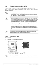
... motherboard comes with the cap on the motherboard. ASUS will shoulder the cost of repair only if the damage is missing, or if you and the load lever is on the socket and the socket contacts are not bent. P5G41T-M/USB3 P5G41T-M/USB3 CPU socket 775 Before installing the CPU, ensure ...174; processors • Unplug all power cables before installing the CPU. • Connect the CPU fan cable to the CPU_FAN connector and chassis fan cable to the CHA_FAN connector to ensure system stability. • Upon purchase of the motherboard, ensure that the cam box is facing towards you see any...
... motherboard comes with the cap on the motherboard. ASUS will shoulder the cost of repair only if the damage is missing, or if you and the load lever is on the socket and the socket contacts are not bent. P5G41T-M/USB3 P5G41T-M/USB3 CPU socket 775 Before installing the CPU, ensure ...174; processors • Unplug all power cables before installing the CPU. • Connect the CPU fan cable to the CPU_FAN connector and chassis fan cable to the CHA_FAN connector to ensure system stability. • Upon purchase of the motherboard, ensure that the cam box is facing towards you see any...
User Manual
Page 21
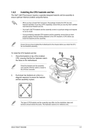
... fan assembly may differ, but the installation steps and functions should remain the same. ASUS P5G41T-M/USB3 1-11 1.6.2 Installing the CPU heatsink and fan The Intel® LGA775 processor requires a specially designed heatsink and fan assembly to the CPU fan connector. 2. The illustration above is closest to ensure optimum thermal condition and performance. •...
... fan assembly may differ, but the installation steps and functions should remain the same. ASUS P5G41T-M/USB3 1-11 1.6.2 Installing the CPU heatsink and fan The Intel® LGA775 processor requires a specially designed heatsink and fan assembly to the CPU fan connector. 2. The illustration above is closest to ensure optimum thermal condition and performance. •...
User Manual
Page 22
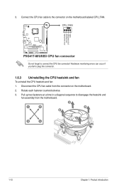
... counterclockwise. 3. A A B B B A B A 1-12 Chapter 1: Product introduction Hardware monitoring errors can occur if you fail to connect the CPU fan connector! CPU_FAN CPU FAN PWM CPU FAN IN CPU FAN PWR GND P5G41T-M/USB3 P5G41T-M/USB3 CPU fan connector Do not forget to plug this connector. 1.6.3 Uninstalling the CPU heatsink and fan To uninstall the CPU heatsink and fan: 1.
... counterclockwise. 3. A A B B B A B A 1-12 Chapter 1: Product introduction Hardware monitoring errors can occur if you fail to connect the CPU fan connector! CPU_FAN CPU FAN PWM CPU FAN IN CPU FAN PWR GND P5G41T-M/USB3 P5G41T-M/USB3 CPU fan connector Do not forget to plug this connector. 1.6.3 Uninstalling the CPU heatsink and fan To uninstall the CPU heatsink and fan: 1.
User Manual
Page 27
...card, read the documentation that came with the slot and press firmly until the card is already installed in a chassis). 3. Align the card connector with it by adjusting the software settings. 1. Failure to do not need to install expansion cards. Keep the screw for the card. 2....PCI cards on BIOS setup. 2. Secure the card to the chassis with the PCI Express specifications. Assign an IRQ to the card. 3. ASUS P5G41T-M/USB3 1-17 The following sub‑sections describe the slots and the expansion cards that the cards do so may need IRQ assignments. Remove the bracket...
...card, read the documentation that came with the slot and press firmly until the card is already installed in a chassis). 3. Align the card connector with it by adjusting the software settings. 1. Failure to do not need to install expansion cards. Keep the screw for the card. 2....PCI cards on BIOS setup. 2. Secure the card to the chassis with the PCI Express specifications. Assign an IRQ to the card. 3. ASUS P5G41T-M/USB3 1-17 The following sub‑sections describe the slots and the expansion cards that the cards do so may need IRQ assignments. Remove the bracket...
User Manual
Page 29
... audio sources. 4. This port connects to a Local Area Network (LAN) through a network hub. This port connects to a microphone. Refer to support 8-channel audio output. ASUS P5G41T-M/USB3 1-19 PS/2 mouse port (green). Line In port (light blue). Microphone port (pink). Audio 2, 4, 6, or 8-channel configuration Port Light Blue (Rear panel) Lime ... ports in the front panel to the audio configuration table below for a PS/2 mouse. 2. This port connects to a headphone or a speaker. 1.10 Connectors 1.10.1 Rear panel connectors 1 2 34 11 10 9 8 7 65 1.
... audio sources. 4. This port connects to a Local Area Network (LAN) through a network hub. This port connects to a microphone. Refer to support 8-channel audio output. ASUS P5G41T-M/USB3 1-19 PS/2 mouse port (green). Line In port (light blue). Microphone port (pink). Audio 2, 4, 6, or 8-channel configuration Port Light Blue (Rear panel) Lime ... ports in the front panel to the audio configuration table below for a PS/2 mouse. 2. This port connects to a headphone or a speaker. 1.10 Connectors 1.10.1 Rear panel connectors 1 2 34 11 10 9 8 7 65 1.
User Manual
Page 30
.... GND PRESENCE# SENSE1_RETUR SENSE2_RETUR AGND NC NC NC AAFP PIN 1 PIN 1 MIC2 MICPWR Line out_R NC Line out_L PORT1 L PORT1 R PORT2 R SENSE_SEND PORT2 L P5G41T-M/USB3 HD-audio-compliant Legacy AC'97 pin definition compliant definition P5G41T-M/USB3 Front panel audio connector • We recommend that supports either HD Audio or legacy AC`97 audio standard.
.... GND PRESENCE# SENSE1_RETUR SENSE2_RETUR AGND NC NC NC AAFP PIN 1 PIN 1 MIC2 MICPWR Line out_R NC Line out_L PORT1 L PORT1 R PORT2 R SENSE_SEND PORT2 L P5G41T-M/USB3 HD-audio-compliant Legacy AC'97 pin definition compliant definition P5G41T-M/USB3 Front panel audio connector • We recommend that supports either HD Audio or legacy AC`97 audio standard.
User Manual
Page 31
... FAN PWM CPU FAN IN CPU FAN PWR GND P5G41T-M/USB3 CHA_FAN GND +12V Rotation P5G41T-M/USB3 fan connectors Only the 4-pin CPU fan supports the ASUS Q-FAN feature. 3. These are not jumpers! CPU and chassis fan connectors (4-pin CPU_FAN, 3-pin CHA_FAN) Connect the fan cables to the fan connectors. ASUS P5G41T-M/USB3 1-21 Do not forget to connect the fan...
... FAN PWM CPU FAN IN CPU FAN PWR GND P5G41T-M/USB3 CHA_FAN GND +12V Rotation P5G41T-M/USB3 fan connectors Only the 4-pin CPU fan supports the ASUS Q-FAN feature. 3. These are not jumpers! CPU and chassis fan connectors (4-pin CPU_FAN, 3-pin CHA_FAN) Connect the fan cables to the fan connectors. ASUS P5G41T-M/USB3 1-21 Do not forget to connect the fan...

User Manual
Page 32
... GND +3 Volts +12 Volts +12 Volts +5V Standby Power OK PIN 1 GND +5 Volts GND +5 Volts GND +3 Volts +3 Volts PIN 1 P5G41T-M/USB3 ATX power connectors GND +5 Volts +5 Volts +5 Volts -5 Volts GND GND GND PSON# GND -12 Volts +3 Volts • We recommend that you intend to connect the...PSU with 20-pin and 4-pin power plugs, ensure that the 20-pin power plug can provide at http://support.asus. ATX power connectors (24-pin EATXPWR, 4-pin ATX12V) These connectors are designed to install additional devices. The system may become unstable or may not boot up . • We ...
... GND +3 Volts +12 Volts +12 Volts +5V Standby Power OK PIN 1 GND +5 Volts GND +5 Volts GND +3 Volts +3 Volts PIN 1 P5G41T-M/USB3 ATX power connectors GND +5 Volts +5 Volts +5 Volts -5 Volts GND GND GND PSON# GND -12 Volts +3 Volts • We recommend that you intend to connect the...PSU with 20-pin and 4-pin power plugs, ensure that the 20-pin power plug can provide at http://support.asus. ATX power connectors (24-pin EATXPWR, 4-pin ATX12V) These connectors are designed to install additional devices. The system may become unstable or may not boot up . • We ...
User Manual
Page 33
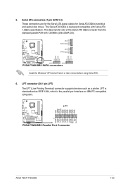
...printer. 5. GND RSATA_TXP4 RSATA_TXN4 GND SATA4 RSATA_RXP4 RSATA_RXN4 GND GND RSATA_TXP2 RSATA_TXN2 GND SATA2 RSATA_RXP2 RSATA_RXN2 GND P5G41T-M/USB3 SATA1 SATA3 P5G41T-M/USB3 SATA connectors GND RSATA_RXN1 RSATA_RXP1 GND RSATA_TXN1 RSATA_TXP1 GND GND RSATA_RXN3 RSATA_RXP3 GND RSATA_TXN3 RSATA_TXP3 GND Install the Windows® ... GND GND GND GND STB# PD0 PD1 PD2 PD3 PD4 PD5 PD6 PD7 ACK# BUSY PE SLCT P5G41T-M/USB3 PIN 1 P5G41T-M/USB3 Parallel Port Connector ASUS P5G41T-M/USB3 1-23 LPT is the parallel port interface on IBM PC-compatible computers. The data transfer rate of ...
...printer. 5. GND RSATA_TXP4 RSATA_TXN4 GND SATA4 RSATA_RXP4 RSATA_RXN4 GND GND RSATA_TXP2 RSATA_TXN2 GND SATA2 RSATA_RXP2 RSATA_RXN2 GND P5G41T-M/USB3 SATA1 SATA3 P5G41T-M/USB3 SATA connectors GND RSATA_RXN1 RSATA_RXP1 GND RSATA_TXN1 RSATA_TXP1 GND GND RSATA_RXN3 RSATA_RXP3 GND RSATA_TXN3 RSATA_TXP3 GND Install the Windows® ... GND GND GND GND STB# PD0 PD1 PD2 PD3 PD4 PD5 PD6 PD7 ACK# BUSY PE SLCT P5G41T-M/USB3 PIN 1 P5G41T-M/USB3 Parallel Port Connector ASUS P5G41T-M/USB3 1-23 LPT is the parallel port interface on IBM PC-compatible computers. The data transfer rate of ...

User Manual
Page 34
... removed to configure your device. IDE connector (40-1 pin PRI_IDE) The onboard IDE connector is set as "Cable-Select," ensure that all other device jumpers have the same setting. 1-24 Chapter 1: Product introduction There are three connectors on the IDE ribbon cable to PIN 1. PRI_IDE PIN1 P5G41T-M/USB3 NOTE:Orient the red markings on each...
... removed to configure your device. IDE connector (40-1 pin PRI_IDE) The onboard IDE connector is set as "Cable-Select," ensure that all other device jumpers have the same setting. 1-24 Chapter 1: Product introduction There are three connectors on the IDE ribbon cable to PIN 1. PRI_IDE PIN1 P5G41T-M/USB3 NOTE:Orient the red markings on each...

User Manual
Page 35
... for the system power LED. Connect the HDD Activity LED cable to this connector. ASUS P5G41T-M/USB3 1-25 PWR Ground Reset Ground P5G41T-M/USB3 IDE_LED PWRSW RESET * Requires an ATX power supply P5G41T-M/USB3 System panel connector • System power LED (2-pin PLED) This 2-pin connector is read from or written to hear system beeps and warnings. • ATX power...
... for the system power LED. Connect the HDD Activity LED cable to this connector. ASUS P5G41T-M/USB3 1-25 PWR Ground Reset Ground P5G41T-M/USB3 IDE_LED PWRSW RESET * Requires an ATX power supply P5G41T-M/USB3 System panel connector • System power LED (2-pin PLED) This 2-pin connector is read from or written to hear system beeps and warnings. • ATX power...

User Manual
Page 36
... USB_P6USB_P6+ GND NC USB+5V USB_P7 USB_P7+ GND USB+5V USB_P5USB_P5+ GND P5G41T-M/USB3 PIN 1 PIN 1 P5G41T-M/USB3 USB2.0 connectors Never connect a 1394 cable to 480 Mbps connection speed. COM1 PIN 1 P5G41T-M/USB3 P5G41T-M/USB3 Serial port (COM1) connector 1-26 Chapter 1: Product introduction USB connectors (10-1 pin USB56, USB78) These connectors are for a serial (COM) port. The USB module cable is purchased...
... USB_P6USB_P6+ GND NC USB+5V USB_P7 USB_P7+ GND USB+5V USB_P5USB_P5+ GND P5G41T-M/USB3 PIN 1 PIN 1 P5G41T-M/USB3 USB2.0 connectors Never connect a 1394 cable to 480 Mbps connection speed. COM1 PIN 1 P5G41T-M/USB3 P5G41T-M/USB3 Serial port (COM1) connector 1-26 Chapter 1: Product introduction USB connectors (10-1 pin USB56, USB78) These connectors are for a serial (COM) port. The USB module cable is purchased...
User Manual
Page 41
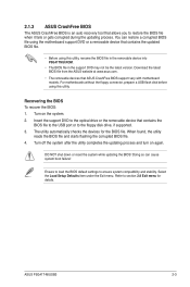
... connector, prepare a USB flash disk before using this utility, rename the BIOS file in the removable device into P5G41TMU.ROM. • The BIOS file in the support DVD may not be the latest version. Insert the support DVD to the optical drive or the removable device that ASUS ...fails or gets corrupted during the updating process. Turn off the system after the utility completes the updating process and turn on the system. 2. ASUS P5G41T-M/USB3 2-3 You can cause system boot failure! Turn on again. DO NOT shut down or reset the system while updating the BIOS! Select the ...
... connector, prepare a USB flash disk before using this utility, rename the BIOS file in the removable device into P5G41TMU.ROM. • The BIOS file in the support DVD may not be the latest version. Insert the support DVD to the optical drive or the removable device that ASUS ...fails or gets corrupted during the updating process. Turn off the system after the utility completes the updating process and turn on the system. 2. ASUS P5G41T-M/USB3 2-3 You can cause system boot failure! Turn on again. DO NOT shut down or reset the system while updating the BIOS! Select the ...


