User Manual
Page 2
...service will not be registered trademarks or copyrights of alteration is licensed under the General Public License ("GPL") and under the Lesser General Public License Version ("LGPL"). SPECIFICATIONS AND INFORMATION CONTAINED IN THIS MANUAL ARE FURNISHED FOR INFORMATIONAL USE ONLY, AND ARE SUBJECT TO CHANGE...http://support.asus.com/download; The GPL and LGPL licensed code in this manual, including the products and software described in the GPL) for backup purposes, without intent to : ASUSTeK Computer Inc. ASUS PROVIDES THIS MANUAL "AS IS" WITHOUT WARRANTY OF ANY KIND, EITHER EXPRESS OR...
...service will not be registered trademarks or copyrights of alteration is licensed under the General Public License ("GPL") and under the Lesser General Public License Version ("LGPL"). SPECIFICATIONS AND INFORMATION CONTAINED IN THIS MANUAL ARE FURNISHED FOR INFORMATIONAL USE ONLY, AND ARE SUBJECT TO CHANGE...http://support.asus.com/download; The GPL and LGPL licensed code in this manual, including the products and software described in the GPL) for backup purposes, without intent to : ASUSTeK Computer Inc. ASUS PROVIDES THIS MANUAL "AS IS" WITHOUT WARRANTY OF ANY KIND, EITHER EXPRESS OR...
User Manual
Page 10
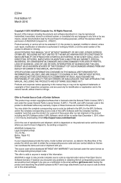
...x USB 2.0/1.1 connectors support additional 4 USB 2.0/1.1 ports 1 x IDE connector 4 x Serial ATA connectors 1 x Front panel audio connector 1 x System panel connector 1 x S/PDIF Out connector 1 x LPT connector 1 x COM connector 1 x CPU fan connector 1 x Chassis fan connector 1 x 24-pin EATX power connector 1 x 4-pin ATX 12V power connector 8Mb Flash ROM, AMI BIOS, PnP, DMI 2.0, WfM 2.0, ACPI 2.0a, SM BIOS 2.5 WOL, PXE, WOR by Ring, PME Wake up 1 x Ultra DMA 100/66/33 cable 2 x Serial ATA cables 1 x I/O shield 1 x User Manual Drivers ASUS PC Probe II ASUS Update Anti-Virus software (OEM version...
...x USB 2.0/1.1 connectors support additional 4 USB 2.0/1.1 ports 1 x IDE connector 4 x Serial ATA connectors 1 x Front panel audio connector 1 x System panel connector 1 x S/PDIF Out connector 1 x LPT connector 1 x COM connector 1 x CPU fan connector 1 x Chassis fan connector 1 x 24-pin EATX power connector 1 x 4-pin ATX 12V power connector 8Mb Flash ROM, AMI BIOS, PnP, DMI 2.0, WfM 2.0, ACPI 2.0a, SM BIOS 2.5 WOL, PXE, WOR by Ring, PME Wake up 1 x Ultra DMA 100/66/33 cable 2 x Serial ATA cables 1 x I/O shield 1 x User Manual Drivers ASUS PC Probe II ASUS Update Anti-Virus software (OEM version...
User Manual
Page 13
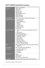
.... ASUS P5G41T-M/USB3 1-3 ASUS Turbo Key ASUS Turbo Key allows you instantly access the Internet and key applications before turning on the computer. • The actual boot time depends on your favorite photo into an overclocking button. When installing it on SATA HDDs, USB HDDs and flash drives with minimal noise. ASUS MyLogo2™ This feature allows you to restore a corrupted BIOS file using the bundled support DVD or a USB flash disk that allows you to the motherboard USB port before entering the Windows...
.... ASUS P5G41T-M/USB3 1-3 ASUS Turbo Key ASUS Turbo Key allows you instantly access the Internet and key applications before turning on the computer. • The actual boot time depends on your favorite photo into an overclocking button. When installing it on SATA HDDs, USB HDDs and flash drives with minimal noise. ASUS MyLogo2™ This feature allows you to restore a corrupted BIOS file using the bundled support DVD or a USB flash disk that allows you to the motherboard USB port before entering the Windows...
User Manual
Page 17
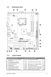
...11. Front panel audio connector (10-1 pin AAFP) 1-20 1-18 13. Serial port connector (10-1 pin COM1) 1-26 ASUS P5G41T-M/USB3 1-7 CPU and chassis fan connectors (4-pin CPU_FAN, 3-pin CHA_FAN) 3. DDR3 DIMM slots 5. Onboard power LED (SB_PWR) Page 1-5 1-21 9. IDE connector (40-1 pin PRI_IDE) 6. System panel connector (20-8 pin PANEL) 1-25 1-8 10. Digital audio connector (4-1 pin SPDIF_OUT) 1-21 1-23 14. Serial ATA connectors (7-pin SATA1-4) Page Connectors/Jumpers/Slots/LED 1-22 8. LPT connector (26-1 pin LPT) 1-23 1-24 12. 1.5.3 Motherboard layout 1 2 3 20...
...11. Front panel audio connector (10-1 pin AAFP) 1-20 1-18 13. Serial port connector (10-1 pin COM1) 1-26 ASUS P5G41T-M/USB3 1-7 CPU and chassis fan connectors (4-pin CPU_FAN, 3-pin CHA_FAN) 3. DDR3 DIMM slots 5. Onboard power LED (SB_PWR) Page 1-5 1-21 9. IDE connector (40-1 pin PRI_IDE) 6. System panel connector (20-8 pin PANEL) 1-25 1-8 10. Digital audio connector (4-1 pin SPDIF_OUT) 1-21 1-23 14. Serial ATA connectors (7-pin SATA1-4) Page Connectors/Jumpers/Slots/LED 1-22 8. LPT connector (26-1 pin LPT) 1-23 1-24 12. 1.5.3 Motherboard layout 1 2 3 20...
User Manual
Page 27
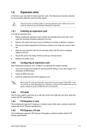
... the software settings. 1. Align the card connector with the PCI Express specifications. 1.8.5 PCI Express x16 slot This motherboard supports a PCI Express x16 graphics card that the cards do so may need IRQ assignments. Assign an IRQ to use . 4. Replace the system cover. 1.8.2 Configuring an expansion card After installing the expansion card, configure it and make the necessary hardware settings for later use . See Chapter 2 for the expansion card. ASUS P5G41T-M/USB3 1-17 Unplug the power cord before adding or removing expansion cards. Failure to...
... the software settings. 1. Align the card connector with the PCI Express specifications. 1.8.5 PCI Express x16 slot This motherboard supports a PCI Express x16 graphics card that the cards do so may need IRQ assignments. Assign an IRQ to use . 4. Replace the system cover. 1.8.2 Configuring an expansion card After installing the expansion card, configure it and make the necessary hardware settings for later use . See Chapter 2 for the expansion card. ASUS P5G41T-M/USB3 1-17 Unplug the power cord before adding or removing expansion cards. Failure to...
User Manual
Page 37
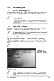
... Drivers, Utilities, Manuals, and Contact tabs to change at www.asus.com for reference only. The contents of the Support DVD to avail all motherboard features. Double-click the ASSETUP.EXE to the optical drive. If Autorun is enabled on your computer, the DVD automatically displays the Specials screen which contains the unique feature of your hardware. • Motherboard settings and hardware options vary. 1.11 Software support 1.11.1 Installing...
... Drivers, Utilities, Manuals, and Contact tabs to change at www.asus.com for reference only. The contents of the Support DVD to avail all motherboard features. Double-click the ASSETUP.EXE to the optical drive. If Autorun is enabled on your computer, the DVD automatically displays the Specials screen which contains the unique feature of your hardware. • Motherboard settings and hardware options vary. 1.11 Software support 1.11.1 Installing...
User Manual
Page 39
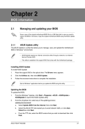
... case you to manage, save, and update the motherboard BIOS in the support DVD that you update the BIOS using the ASUS Update utility. 2.1.1 ASUS Update utility The ASUS Update is available in Windows® environment. • ASUS Update requires an Internet connection either through a network or an Internet Service Provider (ISP). • This utility is a utility that allows you to avoid network traffic, or click Auto Select then click Next. b. Follow the onscreen instructions to launch the ASUS Update utility. 2. ASUS P5G41T-M/USB3 2-1 Updating...
... case you to manage, save, and update the motherboard BIOS in the support DVD that you update the BIOS using the ASUS Update utility. 2.1.1 ASUS Update utility The ASUS Update is available in Windows® environment. • ASUS Update requires an Internet connection either through a network or an Internet Service Provider (ISP). • This utility is a utility that allows you to avoid network traffic, or click Auto Select then click Next. b. Follow the onscreen instructions to launch the ASUS Update utility. 2. ASUS P5G41T-M/USB3 2-1 Updating...
User Manual
Page 40
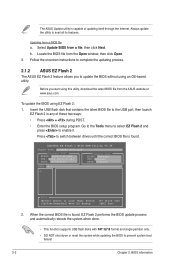
... ASUS website at www.asus.com. To update the BIOS using an OS‑based utility. Updating from the Open window, then click Open. 3. Insert the USB flash disk that contains the latest BIOS file to enable it. b. ASUSTek EZ Flash 2 BIOS ROM Utility V3.36 FLASH TYPE: WINBOND W25X/Q80 Current ROM BOARD: P5G41T-M-USB3 VER: 0306 (H:00 B:02) DATE: 03/24/2010 Update ROM BOARD: Unknown VER: Unknown DATE: Unknown PATH: A:\ A: Note [Enter] Select or Load [Tab] Switch...
... ASUS website at www.asus.com. To update the BIOS using an OS‑based utility. Updating from the Open window, then click Open. 3. Insert the USB flash disk that contains the latest BIOS file to enable it. b. ASUSTek EZ Flash 2 BIOS ROM Utility V3.36 FLASH TYPE: WINBOND W25X/Q80 Current ROM BOARD: P5G41T-M-USB3 VER: 0306 (H:00 B:02) DATE: 03/24/2010 Update ROM BOARD: Unknown VER: Unknown DATE: Unknown PATH: A:\ A: Note [Enter] Select or Load [Tab] Switch...
User Manual
Page 41
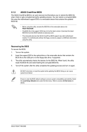
... or reset the system while updating the BIOS! ASUS P5G41T-M/USB3 2-3 For motherboards without the floppy connector, prepare a USB flash disk before using this utility, rename the BIOS file in the removable device into P5G41TMU.ROM. • The BIOS file in the support DVD may not be the latest version. Select the Load Setup Defaults item under the Exit menu. The utility automatically checks the devices for details. Doing so can restore a corrupted BIOS file using this utility. 2.1.3 ASUS CrashFree BIOS The ASUS CrashFree BIOS is an auto recovery tool...
... or reset the system while updating the BIOS! ASUS P5G41T-M/USB3 2-3 For motherboards without the floppy connector, prepare a USB flash disk before using this utility, rename the BIOS file in the removable device into P5G41TMU.ROM. • The BIOS file in the support DVD may not be the latest version. Select the Load Setup Defaults item under the Exit menu. The utility automatically checks the devices for details. Doing so can restore a corrupted BIOS file using this utility. 2.1.3 ASUS CrashFree BIOS The ASUS CrashFree BIOS is an auto recovery tool...
User Manual
Page 44
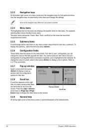
... item on the menu bar displays the specific items for the menu items. If an item is user- You cannot select an item that is not userconfigurable.A configurable field is enclosed in the menu and change the settings. are the navigation keys for that item. Use [+] or [-] to display a pop-up window screen. Main Advanced BIOS SETUP UTILITY Power Boot Tools Exit Suspend Mode ACPI 2.0 Support ACPI APIC support APM Configuration Hardware Monitor [Auto] [Disabled] [EDniOsapabtbilloendesd] Enabled Use [ENTER], [TAB] or [SHIFT...
... item on the menu bar displays the specific items for the menu items. If an item is user- You cannot select an item that is not userconfigurable.A configurable field is enclosed in the menu and change the settings. are the navigation keys for that item. Use [+] or [-] to display a pop-up window screen. Main Advanced BIOS SETUP UTILITY Power Boot Tools Exit Suspend Mode ACPI 2.0 Support ACPI APIC support APM Configuration Hardware Monitor [Auto] [Disabled] [EDniOsapabtbilloendesd] Enabled Use [ENTER], [TAB] or [SHIFT...
User Manual
Page 45
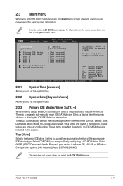
... (Device, Vendor, Size, LBA Mode, Block Mode, PIO Mode, Async DMA, Ultra DMA, and SMART monitoring). Use [+] or [-] to display the IDE/SATA device information. Type [Auto] Selects the type of IDE/SATA devices. Select ARMD (ATAPI Removable Media Device) if your device is installed in the system. Select a device item then press to configure system time. These values are specifically configuring a CD-ROM drive. Refer to section 2.2.1 BIOS menu screen for each IDE/SATA device. These items show Not Detected if no IDE/SATA device is...
... (Device, Vendor, Size, LBA Mode, Block Mode, PIO Mode, Async DMA, Ultra DMA, and SMART monitoring). Use [+] or [-] to display the IDE/SATA device information. Type [Auto] Selects the type of IDE/SATA devices. Select ARMD (ATAPI Removable Media Device) if your device is installed in the system. Select a device item then press to configure system time. These values are specifically configuring a CD-ROM drive. Refer to section 2.2.1 BIOS menu screen for each IDE/SATA device. These items show Not Detected if no IDE/SATA device is...
User Manual
Page 46
...sectors transfers. When set to [Auto], the data transfer from and to set or change the configurations for detecting ATA/ATAPI devices. Configuration options: [Disabled] [Enabled] 2.3.4 Storage Configuration The items in the system. When set to [Disabled], the data transfer from and to the device occurs multiple sectors at a time. Configuration options: [Auto] SMART Monitoring [Auto] Sets the Smart Monitoring, Analysis, and Reporting Technology. Configuration options: [0] [5] [10] [15] [20] [25] [30] [35] 2-8 Chapter 2: BIOS information ATA/IDE Configuration [Enhanced] Allows...
...sectors transfers. When set to [Auto], the data transfer from and to set or change the configurations for detecting ATA/ATAPI devices. Configuration options: [Disabled] [Enabled] 2.3.4 Storage Configuration The items in the system. When set to [Disabled], the data transfer from and to the device occurs multiple sectors at a time. Configuration options: [Auto] SMART Monitoring [Auto] Sets the Smart Monitoring, Analysis, and Reporting Technology. Configuration options: [0] [5] [10] [15] [20] [25] [30] [35] 2-8 Chapter 2: BIOS information ATA/IDE Configuration [Enhanced] Allows...
User Manual
Page 47
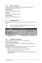
... Memory Displays the auto-detected system memory. 2.4 Advanced menu The Advanced menu items allow you to change the settings for PCI/PCIe slot. Main Advanced Power BIOS SETUP UTILITY Boot Tools Exit JumperFree Configuration CPU Configuration Chipset Onboard Devices Configuration USB Configuration PCIPnP Adjust System frequency/voltage. 2.4.1 JumperFree Configuration The items in this menu allows you to malfunction. PCI/PCIe CLK Status [Enabled] Enables or disables clock for the CPU and other system devices. allows you to achieve desired CPU internal frequency. ASUS P5G41T-M/USB3...
... Memory Displays the auto-detected system memory. 2.4 Advanced menu The Advanced menu items allow you to change the settings for PCI/PCIe slot. Main Advanced Power BIOS SETUP UTILITY Boot Tools Exit JumperFree Configuration CPU Configuration Chipset Onboard Devices Configuration USB Configuration PCIPnP Adjust System frequency/voltage. 2.4.1 JumperFree Configuration The items in this menu allows you to malfunction. PCI/PCIe CLK Status [Enabled] Enables or disables clock for the CPU and other system devices. allows you to achieve desired CPU internal frequency. ASUS P5G41T-M/USB3...
User Manual
Page 50
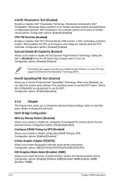
When enabled, the CPU core frequency and voltage are reduced when the CPU overheats. Configuration options: [Enabled] [Disabled] 2.4.3 Chipset The Chipset menu allows you installed an Intel® Pentium® 4 or later CPU that supports the Enhanced Intel SpeedStep® Technology (EIST). Configuration options: [IGD] [PCI/IGD] [PCI/PEG] [PEG/IGD] [PEG/PCI] IGD Graphics Mode Select [Enabled, 32MB] Allows you do not want to use the EIST. Configuration options: [Disabled] [Enabled] The following item appears only when you to run...
When enabled, the CPU core frequency and voltage are reduced when the CPU overheats. Configuration options: [Enabled] [Disabled] 2.4.3 Chipset The Chipset menu allows you installed an Intel® Pentium® 4 or later CPU that supports the Enhanced Intel SpeedStep® Technology (EIST). Configuration options: [IGD] [PCI/IGD] [PCI/PEG] [PEG/IGD] [PEG/PCI] IGD Graphics Mode Select [Enabled, 32MB] Allows you do not want to use the EIST. Configuration options: [Disabled] [Enabled] The following item appears only when you to run...
User Manual
Page 51
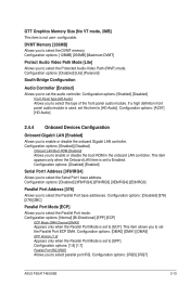
... Audio Video Path Mode [Lite] Allows you to enable or disable the boot ROM in the onboard LAN controller. Configuration options: [Disabled] [Lite] [Paranoid] South Bridge Configuration Audio Controller [Enabled] Allows you to select the Serial Port1 base address. If a high definition front panel audio module is set to [ECP]. Configuration options: [Enabled] [Disabled] Onboard LAN Boot ROM [Disabled] Allows you to select the Parallel Port base addresses. Configuration options: [1.9] [1.7] Parallel Port IRQ [IRQ7] Allows you to set the audio controller. GTT Graphics Memory Size...
... Audio Video Path Mode [Lite] Allows you to enable or disable the boot ROM in the onboard LAN controller. Configuration options: [Disabled] [Lite] [Paranoid] South Bridge Configuration Audio Controller [Enabled] Allows you to select the Serial Port1 base address. If a high definition front panel audio module is set to [ECP]. Configuration options: [Enabled] [Disabled] Onboard LAN Boot ROM [Disabled] Allows you to select the Parallel Port base addresses. Configuration options: [1.9] [1.7] Parallel Port IRQ [IRQ7] Allows you to set the audio controller. GTT Graphics Memory Size...
User Manual
Page 52
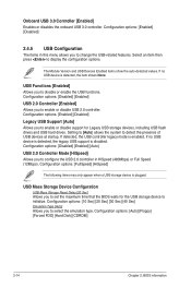
...for Legacy USB storage devices, including USB flash drives and USB hard drives. Configuration options: [FullSpeed] [HiSpeed] The following items may only appear when a USB storage device is enabled. If detected, the USB controller legacy mode is plugged. USB Mass Storage Device Configuration USB Mass Storage Reset Delay [20 Sec] Allows you to initialize. Configuration options: [Enabled] [Disabled] Legacy USB Support [Auto] Allows you to enable or disable support for the USB storage device to disable or enable the USB functions. Onboard USB 3.0 Controller [Enabled] Enables or...
...for Legacy USB storage devices, including USB flash drives and USB hard drives. Configuration options: [FullSpeed] [HiSpeed] The following items may only appear when a USB storage device is enabled. If detected, the USB controller legacy mode is plugged. USB Mass Storage Device Configuration USB Mass Storage Reset Delay [20 Sec] Allows you to initialize. Configuration options: [Enabled] [Disabled] Legacy USB Support [Auto] Allows you to enable or disable support for the USB storage device to disable or enable the USB functions. Onboard USB 3.0 Controller [Enabled] Enables or...
User Manual
Page 53
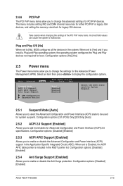
... PCI/PnP or legacy ISA devices, and setting the memory size block for Advanced Configuration and Power Interface (ACPI) 2.0 specifications. Main Advanced Power BIOS SETUP UTILITY Boot Tools Exit Suspend Mode ACPI 2.0 Support ACPI APIC Support Anti Surge Support [Auto] [Enabled] [Enabled] [Enabled] APM Configuration Hardware Monitor Select the ACPI state used for PCI/PnP devices. Configuration options: [Disabled] [Enabled] 2.5.3 ACPI APIC Support [Enabled] Allows you to enable or disable the Advanced Configuration and Power Interface (ACPI) support in the system. Configuration...
... PCI/PnP or legacy ISA devices, and setting the memory size block for Advanced Configuration and Power Interface (ACPI) 2.0 specifications. Main Advanced Power BIOS SETUP UTILITY Boot Tools Exit Suspend Mode ACPI 2.0 Support ACPI APIC Support Anti Surge Support [Auto] [Enabled] [Enabled] [Enabled] APM Configuration Hardware Monitor Select the ACPI state used for PCI/PnP devices. Configuration options: [Disabled] [Enabled] 2.5.3 ACPI APIC Support [Enabled] Allows you to enable or disable the Advanced Configuration and Power Interface (ACPI) support in the system. Configuration...
User Manual
Page 55
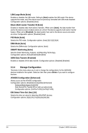
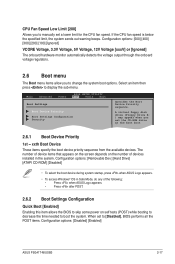
...To access Windows® OS in Safe Mode, do any of devices installed in the system. Main Advanced Power BIOS SETUP UTILITY Boot Tools Exit Boot Settings Boot Device Priority Boot Settings Configuration Security Specifies the Boot Device Priority sequence. A virtual floppy disk drive (Floppy Drive B: ) may appear when you to manually set a lower limit for the CPU fan speed. Select an item then press to [Disabled], BIOS performs all the POST items. Configuration options: [Disabled] [Enabled] ASUS P5G41T-M/USB3 2-17 When set the CD-ROM drive as the first boot device. 2.6.1 Boot...
...To access Windows® OS in Safe Mode, do any of devices installed in the system. Main Advanced Power BIOS SETUP UTILITY Boot Tools Exit Boot Settings Boot Device Priority Boot Settings Configuration Security Specifies the Boot Device Priority sequence. A virtual floppy disk drive (Floppy Drive B: ) may appear when you to manually set a lower limit for the CPU fan speed. Select an item then press to [Disabled], BIOS performs all the POST items. Configuration options: [Disabled] [Enabled] ASUS P5G41T-M/USB3 2-17 When set the CD-ROM drive as the first boot device. 2.6.1 Boot...
User Manual
Page 56
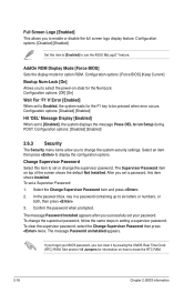
... successfully set to [Enabled], the system displays the message Press DEL to use the ASUS MyLogo2™ feature. To clear the supervisor password, select the Change Supervisor Password then press twice. Configuration options: [Disabled] [Enabled] Set this item to [Enabled] to run Setup during POST. If you forget your password. Change Supervisor Password Select this item shows Installed. The message Password uninstalled appears. AddOn ROM Display Mode [Force BIOS] Sets the display mode for the F1 key to display the configuration options. Configuration options: [Force BIOS...
... successfully set to [Enabled], the system displays the message Press DEL to use the ASUS MyLogo2™ feature. To clear the supervisor password, select the Change Supervisor Password then press twice. Configuration options: [Disabled] [Enabled] Set this item to [Enabled] to run Setup during POST. If you forget your password. Change Supervisor Password Select this item shows Installed. The message Password uninstalled appears. AddOn ROM Display Mode [Force BIOS] Sets the display mode for the F1 key to display the configuration options. Configuration options: [Force BIOS...
User Manual
Page 58
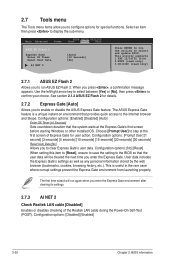
Main Advanced Power BIOS SETUP UTILITY Boot Tools Exit ASUS EZ Flash 2 Express Gate Enter OS Timer Reset User Data AI NET 2 [Auto] [10 Seconds] [No] Press ENTER to run again when you enter the Express Gate environment after clearing its settings. 2.7.3 AI NET 2 Check Realtek LAN cable [Disabled] Enables or disables checking of Express Gate for user action. When you enter the Express Gate. Choose [Prompt User] to stay at the Express Gate's first screen before starting Windows or other installed OS. The...
Main Advanced Power BIOS SETUP UTILITY Boot Tools Exit ASUS EZ Flash 2 Express Gate Enter OS Timer Reset User Data AI NET 2 [Auto] [10 Seconds] [No] Press ENTER to run again when you enter the Express Gate environment after clearing its settings. 2.7.3 AI NET 2 Check Realtek LAN cable [Disabled] Enables or disables checking of Express Gate for user action. When you enter the Express Gate. Choose [Prompt User] to stay at the Express Gate's first screen before starting Windows or other installed OS. The...


