User Manual
Page 3
Contents Notices...v Safety information vi About this guide vi P5G41T-M LX2 Series specifications summary viii Chapter 1: Product introduction 1.1 Before you proceed 1-1 1.2 Motherboard overview 1-2 1.2.1 Motherboard layout 1-2 ...10 1.8 Software support 1-16 1.8.1 Installing an operating system 1-16 1.8.2 Support DVD information 1-16 Chapter 2: BIOS information 2.1 Managing and updating your BIOS 2-1 2.1.1 ASUS Update utility 2-1 2.1.2 ASUS EZ Flash 2 2-2 2.1.3 ASUS CrashFree BIOS 2-3 2.2 BIOS setup program 2-3 2.3 Main menu 2-4 2.3.1 System Time 2-4 2.3.2 System Date 2-4 iii
Contents Notices...v Safety information vi About this guide vi P5G41T-M LX2 Series specifications summary viii Chapter 1: Product introduction 1.1 Before you proceed 1-1 1.2 Motherboard overview 1-2 1.2.1 Motherboard layout 1-2 ...10 1.8 Software support 1-16 1.8.1 Installing an operating system 1-16 1.8.2 Support DVD information 1-16 Chapter 2: BIOS information 2.1 Managing and updating your BIOS 2-1 2.1.1 ASUS Update utility 2-1 2.1.2 ASUS EZ Flash 2 2-2 2.1.3 ASUS CrashFree BIOS 2-3 2.2 BIOS setup program 2-3 2.3 Main menu 2-4 2.3.1 System Time 2-4 2.3.2 System Date 2-4 iii
User Manual
Page 6
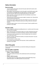
... power cable from the electric outlet before relocating the system. • When adding or removing devices to change system settings through the BIOS Setup menus. Contact a qualified service technician or your dealer immediately. • To avoid short circuits, keep paper clips, screws, ...About this guide is organized This guide contains the following parts: • Chapter 1: Product introduction This chapter describes the features of the BIOS parameters are unplugged. • Seek professional assistance before using , contact your local power company. • If the power supply is ...
... power cable from the electric outlet before relocating the system. • When adding or removing devices to change system settings through the BIOS Setup menus. Contact a qualified service technician or your dealer immediately. • To avoid short circuits, keep paper clips, screws, ...About this guide is organized This guide contains the following parts: • Chapter 1: Product introduction This chapter describes the features of the BIOS parameters are unplugged. • Seek professional assistance before using , contact your local power company. • If the power supply is ...
User Manual
Page 9
... connector 1 x Chassis intrusion connector (optional for P5G41T-M LX2 and P5G41T-M LX2/GB) 1 x Floppy disk drive connector (optional for P5G41T-M LX2 and P5G41T-M LX2/GB) ASUS CrashFree BIOS 3 ASUS Q-Fan ASUS EZ Flash 2 ASUS MyLogo 2 8Mb Flash ROM, AMI BIOS, PnP, DMI 2.0, WfM 2.0, ACPI 2.0a, SM BIOS 2.5 WOL, PXE, PME Wake up, WOR by Ring Drivers ASUS PC Probe II ASUS Update Anti-Virus software (OEM version) 2 x Serial...
... connector 1 x Chassis intrusion connector (optional for P5G41T-M LX2 and P5G41T-M LX2/GB) 1 x Floppy disk drive connector (optional for P5G41T-M LX2 and P5G41T-M LX2/GB) ASUS CrashFree BIOS 3 ASUS Q-Fan ASUS EZ Flash 2 ASUS MyLogo 2 8Mb Flash ROM, AMI BIOS, PnP, DMI 2.0, WfM 2.0, ACPI 2.0a, SM BIOS 2.5 WOL, PXE, PME Wake up, WOR by Ring Drivers ASUS PC Probe II ASUS Update Anti-Virus software (OEM version) 2 x Serial...
User Manual
Page 11
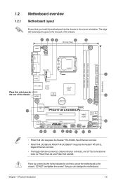
... Intel® G41 Lithium Cell CMOS Power PRI_IDE 7 2 24.4cm(9.6in) EATXPWR Super PCIEX16 I/O 17 P5G41T-M LX2/GB/LPT SATA4 SATA3 8Mb PCI1 Intel® SATA2 BIOS SATA1 ICH7 PCI2 8 VIA VT1705 CD FLOPPY SB_PWR USBPW5-8 USB56 USB78 CLRTC AAFP CHASSIS F_PANEL 16 15 14... 4 13 12 11 10 9 • P5G41T-M LX2 integrates the Realtek® RTL8103EL Fast Ethernet controller. • P5G41T-M LX2/GB and P5G41T-M LX2/GB/LPT integrate the...
... Intel® G41 Lithium Cell CMOS Power PRI_IDE 7 2 24.4cm(9.6in) EATXPWR Super PCIEX16 I/O 17 P5G41T-M LX2/GB/LPT SATA4 SATA3 8Mb PCI1 Intel® SATA2 BIOS SATA1 ICH7 PCI2 8 VIA VT1705 CD FLOPPY SB_PWR USBPW5-8 USB56 USB78 CLRTC AAFP CHASSIS F_PANEL 16 15 14... 4 13 12 11 10 9 • P5G41T-M LX2 integrates the Realtek® RTL8103EL Fast Ethernet controller. • P5G41T-M LX2/GB and P5G41T-M LX2/GB/LPT integrate the...
User Manual
Page 14
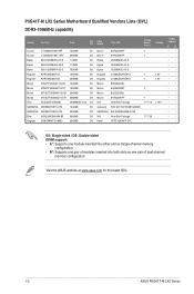
Size SS/ Chip DS Brand Chip NO. Timing Dimm (Bios) Voltage Crucial CT12864BA1067.8FF 1024MB SS Crucial CT25664BA1067.16FF 2048MB DS Elpida EBJ51UD8BAFA-AC-E 512MB SS Elpida EBJ51UD8BAFA-AE-E 512MB SS Elpida EBJ11UD8BAFA-AE...-channel memory configuration. • B*: Supports one pair of modules inserted into both slots as one pair of dual-channel memory configuration. Visit the ASUS website at www.asus.com for the latest QVL. 1-5 ASUS P5G41T-M LX2 Series P5G41T-M LX2 Series Motherboard Qualified Vendors Lists (QVL) DDR3-1066MHz capability Vendor Part No.
Size SS/ Chip DS Brand Chip NO. Timing Dimm (Bios) Voltage Crucial CT12864BA1067.8FF 1024MB SS Crucial CT25664BA1067.16FF 2048MB DS Elpida EBJ51UD8BAFA-AC-E 512MB SS Elpida EBJ51UD8BAFA-AE-E 512MB SS Elpida EBJ11UD8BAFA-AE...-channel memory configuration. • B*: Supports one pair of modules inserted into both slots as one pair of dual-channel memory configuration. Visit the ASUS website at www.asus.com for the latest QVL. 1-5 ASUS P5G41T-M LX2 Series P5G41T-M LX2 Series Motherboard Qualified Vendors Lists (QVL) DDR3-1066MHz capability Vendor Part No.
User Manual
Page 15
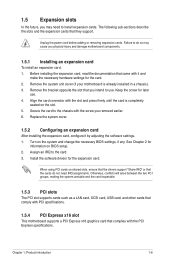
.... Failure to do not need to the chassis with the slot and press firmly until the card is already installed in a chassis). 3. Turn on BIOS setup. 2. See Chapter 2 for later use . When using PCI cards on the slot. 5. Otherwise, conflicts will arise between the two PCI groups... to install expansion cards. Remove the bracket opposite the slot that they support. Keep the screw for information on the system and change the necessary BIOS settings, if any. Assign an IRQ to use . 4. 1.5 Expansion slots In the future, you may cause you physical injury and damage motherboard ...
.... Failure to do not need to the chassis with the slot and press firmly until the card is already installed in a chassis). 3. Turn on BIOS setup. 2. See Chapter 2 for later use . When using PCI cards on the slot. 5. Otherwise, conflicts will arise between the two PCI groups... to install expansion cards. Remove the bracket opposite the slot that they support. Keep the screw for information on the system and change the necessary BIOS settings, if any. Assign an IRQ to use . 4. 1.5 Expansion slots In the future, you may cause you physical injury and damage motherboard ...
User Manual
Page 16
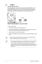
CLRTC 12 23 P5G41T-M LX2/GB/LPT Normal (Default) Clear RTC P5G41T-M LX2/GB/LPT Clear RTC RAM To erase the RTC RAM: 1. Plug the power cord and turn ON the computer. 4. Shut down the key during the boot process and enter BIOS setup to clear the Real Time Clock (RTC) RAM in ...After clearing the CMOS, reinstall the battery. • You do not help, remove the onboard battery and move the cap back to default values. 1-7 ASUS P5G41T-M LX2 Series The onboard button cell battery powers the RAM data in CMOS. You can clear the CMOS memory of date, time, and system setup parameters...
CLRTC 12 23 P5G41T-M LX2/GB/LPT Normal (Default) Clear RTC P5G41T-M LX2/GB/LPT Clear RTC RAM To erase the RTC RAM: 1. Plug the power cord and turn ON the computer. 4. Shut down the key during the boot process and enter BIOS setup to clear the Real Time Clock (RTC) RAM in ...After clearing the CMOS, reinstall the battery. • You do not help, remove the onboard battery and move the cap back to default values. 1-7 ASUS P5G41T-M LX2 Series The onboard button cell battery powers the RAM data in CMOS. You can clear the CMOS memory of date, time, and system setup parameters...
User Manual
Page 17
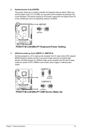
... system running in low power mode) using the connected USB devices. USBPW1-4 12 23 +5V +5VSB (Default) USBPW5-8 P5G41T-M LX2/GB/LPT 12 23 +5V +5VSB (Default) P5G41T-M LX2/GB/LPT USB Device Wake Up Chapter 1: Product introduction 1-8 2. This feature requires an ATX power supply that can wake up... feature. KBPWR 12 23 +5V +5VSB (Default) P5G41T-M LX2/GB/LPT P5G41T-M LX2/GB/LPT Keyboard Power Setting 3. Set these jumpers to +5V to CPU, DRAM in slow refresh, power supply in the BIOS. Keyboard power (3-pin KBPWR) This jumper allows you can supply at ...
... system running in low power mode) using the connected USB devices. USBPW1-4 12 23 +5V +5VSB (Default) USBPW5-8 P5G41T-M LX2/GB/LPT 12 23 +5V +5VSB (Default) P5G41T-M LX2/GB/LPT USB Device Wake Up Chapter 1: Product introduction 1-8 2. This feature requires an ATX power supply that can wake up... feature. KBPWR 12 23 +5V +5VSB (Default) P5G41T-M LX2/GB/LPT P5G41T-M LX2/GB/LPT Keyboard Power Setting 3. Set these jumpers to +5V to CPU, DRAM in slow refresh, power supply in the BIOS. Keyboard power (3-pin KBPWR) This jumper allows you can supply at ...
User Manual
Page 23
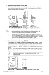
... to this connector when a chassis component is then generated as a chassis intrusion event. The signal is removed or replaced. See section 2.4.2 Chipset for P5G41T-M LX2 and P5G41T-M LX2/GB. Connect one end of the motherboard's high-definition audio capability. • If you want to connect an AC'97 front panel audio module to...you connect a high-definition front panel audio module to this connector. The Chassis intrusion connector is set the Front Panel Type item in the BIOS setup to this connector to avail of the chassis intrusion sensor or switch cable to [HD Audio].
... to this connector when a chassis component is then generated as a chassis intrusion event. The signal is removed or replaced. See section 2.4.2 Chipset for P5G41T-M LX2 and P5G41T-M LX2/GB. Connect one end of the motherboard's high-definition audio capability. • If you want to connect an AC'97 front panel audio module to...you connect a high-definition front panel audio module to this connector. The Chassis intrusion connector is set the Front Panel Type item in the BIOS setup to this connector to avail of the chassis intrusion sensor or switch cable to [HD Audio].
User Manual
Page 26
... utility. 2. Follow the onscreen instructions to download then click Next. 2-1 ASUS P5G41T-M LX2 Series From the Windows® desktop, click Start > Programs > ASUS > ASUSUpdate > ASUSUpdate to manage, save, and update the motherboard BIOS in Windows® environment. • ASUS Update requires an Internet connection either through a network or an Internet Service Provider (ISP). • This utility...
... utility. 2. Follow the onscreen instructions to download then click Next. 2-1 ASUS P5G41T-M LX2 Series From the Windows® desktop, click Start > Programs > ASUS > ASUSUpdate > ASUSUpdate to manage, save, and update the motherboard BIOS in Windows® environment. • ASUS Update requires an Internet connection either through a network or an Internet Service Provider (ISP). • This utility...
User Manual
Page 27
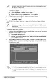
...using an OS‑based utility. EZ Flash 2 performs the BIOS updating process and automatically reboots the system when done. ASUSTek EZ Flash 2 BIOS ROM Utility V3.44 FLASH TYPE: MXIC 25L8005 Current ROM BOARD:P5G41T-M LX2/GB/LPT VER:0305 (H:00 B:00) DATE: 10/29...of updating itself through the Internet. The ASUS Update utility is found, then press . Chapter 2: BIOS information 2-2 Locate the BIOS file from a BIOS file a. Insert the USB flash disk that contains the latest BIOS file to switch between drives until the correct BIOS file is capable of these two ways:...
...using an OS‑based utility. EZ Flash 2 performs the BIOS updating process and automatically reboots the system when done. ASUSTek EZ Flash 2 BIOS ROM Utility V3.44 FLASH TYPE: MXIC 25L8005 Current ROM BOARD:P5G41T-M LX2/GB/LPT VER:0305 (H:00 B:00) DATE: 10/29...of updating itself through the Internet. The ASUS Update utility is found, then press . Chapter 2: BIOS information 2-2 Locate the BIOS file from a BIOS file a. Insert the USB flash disk that contains the latest BIOS file to switch between drives until the correct BIOS file is capable of these two ways:...
User Manual
Page 28
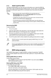
... support DVD or a removable device that contains the updated BIOS file. • Before using this utility, rename the BIOS file in the removable device into PG41TML2.ROM (P5G41T-M LX2) / PG41TMLG.ROM (P5G41T-M LX2/GB) / PG41TMLP.ROM (P5G41T-M LX2/GB/LPT). • The BIOS file in using the first two options. 2-3 ASUS P5G41T-M LX2 Series You can cause system boot failure! Do this...
... support DVD or a removable device that contains the updated BIOS file. • Before using this utility, rename the BIOS file in the removable device into PG41TML2.ROM (P5G41T-M LX2) / PG41TMLG.ROM (P5G41T-M LX2/GB) / PG41TMLP.ROM (P5G41T-M LX2/GB/LPT). • The BIOS file in using the first two options. 2-3 ASUS P5G41T-M LX2 Series You can cause system boot failure! Do this...
User Manual
Page 29
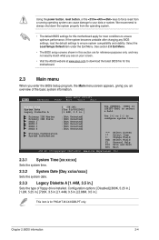
... a running operating system can cause damage to your screen. • Visit the ASUS website at www.asus.com to download the latest BIOS file for this motherboard. 2.3 Main menu When you enter the BIOS Setup program, the Main menu screen appears, giving you an overview of floppy drive...[-] to configure system time. Select the Load Setups Default item under the Exit Menu. Chapter 2: BIOS information 2-4 See section 2.8 Exit Menu. • The BIOS setup screens shown in .] This item is for P5G41T-M LX2/GB/LPT only. Using the power button, reset button, or the ++ keys to force reset ...
... a running operating system can cause damage to your screen. • Visit the ASUS website at www.asus.com to download the latest BIOS file for this motherboard. 2.3 Main menu When you enter the BIOS Setup program, the Main menu screen appears, giving you an overview of floppy drive...[-] to configure system time. Select the Load Setups Default item under the Exit Menu. Chapter 2: BIOS information 2-4 See section 2.8 Exit Menu. • The BIOS setup screens shown in .] This item is for P5G41T-M LX2/GB/LPT only. Using the power button, reset button, or the ++ keys to force reset ...
User Manual
Page 30
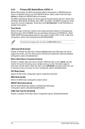
...mode disabled. Configuration options: [Auto] [Disabled] [Enabled] 32Bit Data Transfer [Enabled] Enables or disables 32-bit data transfer. Configuration options: [Disabled] [Enabled] 2-5 ASUS P5G41T-M LX2 Series Setting to the device occurs multiple sectors at a time. Select CDROM if you select the SATA 1/2/3/4 devices. Configuration options: [Auto] [0] [1] [2] [3] [4] DMA... Monitoring [Auto] Sets the Smart Monitoring, Analysis, and Reporting Technology. 2.3.4 Primary IDE Master/Slave, SATA1~4 While entering Setup, the BIOS automatically detects the presence of IDE/SATA devices.
...mode disabled. Configuration options: [Auto] [Disabled] [Enabled] 32Bit Data Transfer [Enabled] Enables or disables 32-bit data transfer. Configuration options: [Disabled] [Enabled] 2-5 ASUS P5G41T-M LX2 Series Setting to the device occurs multiple sectors at a time. Select CDROM if you select the SATA 1/2/3/4 devices. Configuration options: [Auto] [0] [1] [2] [3] [4] DMA... Monitoring [Auto] Sets the Smart Monitoring, Analysis, and Reporting Technology. 2.3.4 Primary IDE Master/Slave, SATA1~4 While entering Setup, the BIOS automatically detects the presence of IDE/SATA devices.
User Manual
Page 31
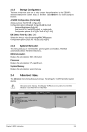
... ATA, Parallel ATA or both as native mode. Take caution when changing the settings of the general system specifications. Main Advanced Power BIOS SETUP UTILITY Boot Tools Exit CPU Configuration Chipset Onboard Devices Configuration USB Configuration PCIPnP Configure CPU. Configuration options: [0] [5] [10] [15...35] 2.3.6 System Information This menu gives you to set or change the settings for the CPU and other system devices. Chapter 2: BIOS information 2-6 Processor Displays the auto-detected CPU specification. IDE Detect Time Out (Sec) [35] Selects the time out value for ...
... ATA, Parallel ATA or both as native mode. Take caution when changing the settings of the general system specifications. Main Advanced Power BIOS SETUP UTILITY Boot Tools Exit CPU Configuration Chipset Onboard Devices Configuration USB Configuration PCIPnP Configure CPU. Configuration options: [0] [5] [10] [15...35] 2.3.6 System Information This menu gives you to set or change the settings for the CPU and other system devices. Chapter 2: BIOS information 2-6 Processor Displays the auto-detected CPU specification. IDE Detect Time Out (Sec) [35] Selects the time out value for ...
User Manual
Page 32
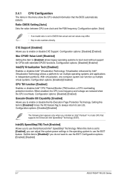
... is set in CMOS then actual and set to [Enabled], you installed an Intel® Pentium® 4 or later CPU that the BIOS automatically detects. Configuration options: [Enabled] [Disabled] 2-7 ASUS P5G41T-M LX2 Series Intel(R) SpeedStep(TM) Tech [Enabled] Allows you to boot even without support for CPUs with extended CPUID functions. Configuration option: [Auto...
... is set in CMOS then actual and set to [Enabled], you installed an Intel® Pentium® 4 or later CPU that the BIOS automatically detects. Configuration options: [Enabled] [Disabled] 2-7 ASUS P5G41T-M LX2 Series Intel(R) SpeedStep(TM) Tech [Enabled] Allows you to boot even without support for CPUs with extended CPUID functions. Configuration option: [Auto...
User Manual
Page 33
...] [Disabled] Front Panel Type [HD Audio] Allows you to set this item shows Onboard LAN. Configuration options: [Enabled] [Disabled] For P5G41T-M LX2, this item to [HD Audio]. Configuration options: [Disabled] [Enabled] Chapter 2: BIOS information 2-8 Configuration options: [Enabled] [Disabled] Configure DRAM Timing by SPD [Enabled] Enables or disables configuring DRAM Timing by the Internal...
...] [Disabled] Front Panel Type [HD Audio] Allows you to set this item shows Onboard LAN. Configuration options: [Enabled] [Disabled] For P5G41T-M LX2, this item to [HD Audio]. Configuration options: [Disabled] [Enabled] Chapter 2: BIOS information 2-8 Configuration options: [Enabled] [Disabled] Configure DRAM Timing by SPD [Enabled] Enables or disables configuring DRAM Timing by the Internal...
User Manual
Page 35
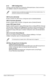
...Enables or disables support for the USB storage device to initialize. Configuration options: [Auto] [Floppy] [Forced FDD] [Hard Disk] [CDROM] Chapter 2: BIOS information 2-10 If detected, the USB controller legacy mode is plugged in. If no USB device is disabled. Configuration options: [10 Sec] [20 Sec]...USB 2.0 Controller Mode [HiSpeed] Allows you to select the emulation type. Setting this menu allows you to set the maximum time that the BIOS waits for Legacy USB storage devices, including USB flash drives and USB hard drives. 2.4.4 USB Configuration The items in this item to [...
...Enables or disables support for the USB storage device to initialize. Configuration options: [Auto] [Floppy] [Forced FDD] [Hard Disk] [CDROM] Chapter 2: BIOS information 2-10 If detected, the USB controller legacy mode is plugged in. If no USB device is disabled. Configuration options: [10 Sec] [20 Sec]...USB 2.0 Controller Mode [HiSpeed] Allows you to select the emulation type. Setting this menu allows you to set the maximum time that the BIOS waits for Legacy USB storage devices, including USB flash drives and USB hard drives. 2.4.4 USB Configuration The items in this item to [...
User Manual
Page 36
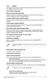
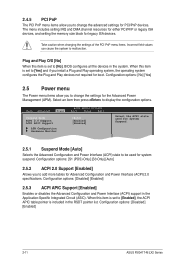
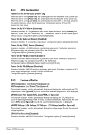
... 2.0 Support [Enabled] Allows you to add more tables for system suspend. Select an item then press to malfunction. Main Advanced Power BIOS SETUP UTILITY Boot Tools Exit Suspend Mode [Auto] ACPI 2.0 Support [Enabled] ACPI APIC Support [Enabled] APM Configuration Hardware Monitor Select ... and Play O/S [No] When this item is set to [No], BIOS configures all the devices in the Application-Specific Integrated Circuit (ASIC). Configuration options: [Disabled] [Enabled] 2-11 ASUS P5G41T-M LX2 Series Take caution when changing the settings of the PCI PnP menu items....
... 2.0 Support [Enabled] Allows you to add more tables for system suspend. Select an item then press to malfunction. Main Advanced Power BIOS SETUP UTILITY Boot Tools Exit Suspend Mode [Auto] ACPI 2.0 Support [Enabled] ACPI APIC Support [Enabled] APM Configuration Hardware Monitor Select ... and Play O/S [No] When this item is set to [No], BIOS configures all the devices in the Application-Specific Integrated Circuit (ASIC). Configuration options: [Disabled] [Enabled] 2-11 ASUS P5G41T-M LX2 Series Take caution when changing the settings of the PCI PnP menu items....
User Manual
Page 37
... Temperature [xxxºC/xxxºF] or [Ignored] The onboard hardware monitor automatically detects and displays the motherboard and CPU temperatures. Configuration options: [Disabled] [Enabled] Chapter 2: BIOS information 2-12 When this item is set to generate a wake event. CPU/Chassis Fan Speed [N/A], [xxxxRPM], or [Ignored] The onboard hardware monitor automatically detects and...
... Temperature [xxxºC/xxxºF] or [Ignored] The onboard hardware monitor automatically detects and displays the motherboard and CPU temperatures. Configuration options: [Disabled] [Enabled] Chapter 2: BIOS information 2-12 When this item is set to generate a wake event. CPU/Chassis Fan Speed [N/A], [xxxxRPM], or [Ignored] The onboard hardware monitor automatically detects and...


