User Manual
Page 9
... connector 1 x Chassis fan connector 1 x 24-pin EATX power connector 1 x 4-pin ATX 12V power connector 1 x Chassis intrusion connector (optional for P5G41T-M LX2 and P5G41T-M LX2/GB) 1 x Floppy disk drive connector (optional for P5G41T-M LX2 and P5G41T-M LX2/GB) ASUS CrashFree BIOS 3 ASUS Q-Fan ASUS EZ Flash 2 ASUS MyLogo 2 8Mb Flash ROM, AMI BIOS, PnP, DMI 2.0, WfM 2.0, ACPI 2.0a, SM BIOS 2.5 WOL, PXE, PME Wake up, WOR...
... connector 1 x Chassis fan connector 1 x 24-pin EATX power connector 1 x 4-pin ATX 12V power connector 1 x Chassis intrusion connector (optional for P5G41T-M LX2 and P5G41T-M LX2/GB) 1 x Floppy disk drive connector (optional for P5G41T-M LX2 and P5G41T-M LX2/GB) ASUS CrashFree BIOS 3 ASUS Q-Fan ASUS EZ Flash 2 ASUS MyLogo 2 8Mb Flash ROM, AMI BIOS, PnP, DMI 2.0, WfM 2.0, ACPI 2.0a, SM BIOS 2.5 WOL, PXE, PME Wake up, WOR...

User Manual
Page 11
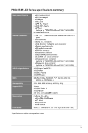
... ICS 9LPRS441 Intel® G41 Lithium Cell CMOS Power PRI_IDE 7 2 24.4cm(9.6in) EATXPWR Super PCIEX16 I/O 17 P5G41T-M LX2/GB/LPT SATA4 SATA3 8Mb PCI1 Intel® SATA2 BIOS SATA1 ICH7 PCI2 8 VIA VT1705 CD FLOPPY SB_PWR USBPW5-8 USB56 ...• P5G41T-M LX2 integrates the Realtek® RTL8103EL Fast Ethernet controller. • P5G41T-M LX2/GB and P5G41T-M LX2/GB/LPT integrate the Realtek® RTL8112L Gigabit Ethernet controller. • The floppy disk drive connector, chassis intrusion connector, and LPT port are optional items for P5G41T-M LX2 and P5G41T-M LX2/GB. The ...
... ICS 9LPRS441 Intel® G41 Lithium Cell CMOS Power PRI_IDE 7 2 24.4cm(9.6in) EATXPWR Super PCIEX16 I/O 17 P5G41T-M LX2/GB/LPT SATA4 SATA3 8Mb PCI1 Intel® SATA2 BIOS SATA1 ICH7 PCI2 8 VIA VT1705 CD FLOPPY SB_PWR USBPW5-8 USB56 ...• P5G41T-M LX2 integrates the Realtek® RTL8103EL Fast Ethernet controller. • P5G41T-M LX2/GB and P5G41T-M LX2/GB/LPT integrate the Realtek® RTL8112L Gigabit Ethernet controller. • The floppy disk drive connector, chassis intrusion connector, and LPT port are optional items for P5G41T-M LX2 and P5G41T-M LX2/GB. The ...

User Manual
Page 12
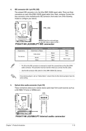
... to the PnP cap/socket contacts/motherboard components. Standby power LED (SB_PWR) 1-8 13. Floppy disk drive connector (34-1 pin FLOPPY) 1-4 15. ASUS will shoulder the cost of the motherboard, ensure that the PnP cap is shipment/transit-related. •...(7-pin SATA1-4) 9. Optical drive audio connector (4-pin CD) 1-12 16. ASUS will process Return Merchandise Authorization (RMA) requests only if the motherboard comes with the Intel® Enhanced Intel SpeedStep® Technology (EIST) and Hyper-Threading Technology. 1-3 ASUS P5G41T-M LX2 Series The motherboard supports Intel...
... to the PnP cap/socket contacts/motherboard components. Standby power LED (SB_PWR) 1-8 13. Floppy disk drive connector (34-1 pin FLOPPY) 1-4 15. ASUS will shoulder the cost of the motherboard, ensure that the PnP cap is shipment/transit-related. •...(7-pin SATA1-4) 9. Optical drive audio connector (4-pin CD) 1-12 16. ASUS will process Return Merchandise Authorization (RMA) requests only if the motherboard comes with the Intel® Enhanced Intel SpeedStep® Technology (EIST) and Hyper-Threading Technology. 1-3 ASUS P5G41T-M LX2 Series The motherboard supports Intel...
User Manual
Page 20
... fan cables to the fan connectors. These are for the Serial ATA signal cables for Serial ATA 3Gb/s hard disk drives and optical disk drives. The Serial ATA 3Gb/s is faster than the standard parallel ATA (133 MB/s). Do not place jumper caps on ... GND RSATA_TXN2 RSATA_TXP2 GND GND RSATA_RXN1 RSATA_RXP1 GND RSATA_TXN1 RSATA_TXP1 GND P5G41T-M LX2/GB/LPT SATA2 SATA1 P5G41T-M LX2/GB/LPT SATA connectors 1-11 ASUS P5G41T-M LX2 Series Insufficient air flow inside the system may damage the motherboard components. 2. P5G41T-M LX2/GB/LPT CHA_FAN Rotation +12V GND CPU_FAN CPU FAN PWM CPU FAN...
... fan cables to the fan connectors. These are for the Serial ATA signal cables for Serial ATA 3Gb/s hard disk drives and optical disk drives. The Serial ATA 3Gb/s is faster than the standard parallel ATA (133 MB/s). Do not place jumper caps on ... GND RSATA_TXN2 RSATA_TXP2 GND GND RSATA_RXN1 RSATA_RXP1 GND RSATA_TXN1 RSATA_TXP1 GND P5G41T-M LX2/GB/LPT SATA2 SATA1 P5G41T-M LX2/GB/LPT SATA connectors 1-11 ASUS P5G41T-M LX2 Series Insufficient air flow inside the system may damage the motherboard components. 2. P5G41T-M LX2/GB/LPT CHA_FAN Rotation +12V GND CPU_FAN CPU FAN PWM CPU FAN...
User Manual
Page 21
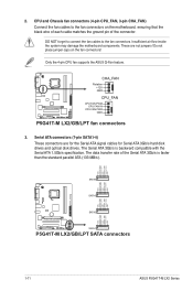
...the covered hole on each Ultra DMA 100/66 signal cable: blue, black, and gray. CD Right Audio Channel GND GND Left Audio Channel P5G41T-M LX2/GB/LPT P5G41T-M LX2/GB/LPT Internal audio connector Chapter 1: Product introduction 1-12 If any device jumper is set as a CD-ROM, TV tuner, or MPEG card... Black Gray Black or gray • Pin 20 on the IDE connector is for Ultra DMA 100/66 IDE devices. P5G41T-M LX2/GB/LPT IDE connector Single device Two devices Drive jumper setting Cable-Select or Master Cable-Select Master Slave Mode of the following modes to PIN 1. PIN1 PRI_IDE...
...the covered hole on each Ultra DMA 100/66 signal cable: blue, black, and gray. CD Right Audio Channel GND GND Left Audio Channel P5G41T-M LX2/GB/LPT P5G41T-M LX2/GB/LPT Internal audio connector Chapter 1: Product introduction 1-12 If any device jumper is set as a CD-ROM, TV tuner, or MPEG card... Black Gray Black or gray • Pin 20 on the IDE connector is for Ultra DMA 100/66 IDE devices. P5G41T-M LX2/GB/LPT IDE connector Single device Two devices Drive jumper setting Cable-Select or Master Cable-Select Master Slave Mode of the following modes to PIN 1. PIN1 PRI_IDE...
User Manual
Page 22
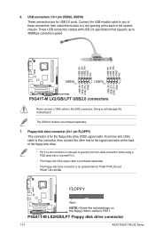
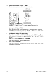
... connector, then connect the other end to the signal connector at the back of the floppy disk drive. • Pin 5 on the floppy ribbon cable to 480Mbps connection speed. P5G41T-M LX2/GB/LPT Floppy disk drive connector 1-13 ASUS P5G41T-M LX2 Series 6. Connect the USB module cable to any of these connectors, then install the module to the...
... connector, then connect the other end to the signal connector at the back of the floppy disk drive. • Pin 5 on the floppy ribbon cable to 480Mbps connection speed. P5G41T-M LX2/GB/LPT Floppy disk drive connector 1-13 ASUS P5G41T-M LX2 Series 6. Connect the USB module cable to any of these connectors, then install the module to the...
User Manual
Page 24
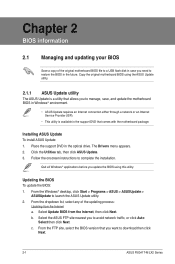
...F_PANEL PWR LED PWR BTN PIN 1 P5G41T-M LX2/GB/LPT HD LED RESET P5G41T-M LX2/GB/LPT System panel connector • System power LED (2-pin PLED) This 2-pin connector is for the chassis-mounted reset button for system reboot without turning off the system power. 1-15 ASUS P5G41T-M LX2 Series Connect the HDD Activity LED cable...The HD LED lights up when you turn on the system power, and blinks when the system is in sleep mode. • Hard disk drive activity LED (2-pin +HDLED) This 2-pin connector is read from or written to this connector. PLED+ PLEDPWR GND IDE_LED+ IDE_LED- The system...
...F_PANEL PWR LED PWR BTN PIN 1 P5G41T-M LX2/GB/LPT HD LED RESET P5G41T-M LX2/GB/LPT System panel connector • System power LED (2-pin PLED) This 2-pin connector is for the chassis-mounted reset button for system reboot without turning off the system power. 1-15 ASUS P5G41T-M LX2 Series Connect the HDD Activity LED cable...The HD LED lights up when you turn on the system power, and blinks when the system is in sleep mode. • Hard disk drive activity LED (2-pin +HDLED) This 2-pin connector is read from or written to this connector. PLED+ PLEDPWR GND IDE_LED+ IDE_LED- The system...

User Manual
Page 25
...8226; Ensure that you can install to maximize the features of your computer. The contents of the Support DVD to change at www.asus.com for better compatibility and system stability. 1.8.2 Support DVD information The Support DVD that comes with the motherboard package contains the drivers,...the BIN folder. To run the Support DVD Place the Support DVD to run the DVD. Double-click the ASSETUP.EXE to the optical drive. Chapter 1: Product introduction 1-16 1.8 Software support 1.8.1 Installing an operating system This motherboard supports Windows® XP/Vista/7 operating systems (OS...
...8226; Ensure that you can install to maximize the features of your computer. The contents of the Support DVD to change at www.asus.com for better compatibility and system stability. 1.8.2 Support DVD information The Support DVD that comes with the motherboard package contains the drivers,...the BIN folder. To run the Support DVD Place the Support DVD to run the DVD. Double-click the ASSETUP.EXE to the optical drive. Chapter 1: Product introduction 1-16 1.8 Software support 1.8.1 Installing an operating system This motherboard supports Windows® XP/Vista/7 operating systems (OS...
User Manual
Page 26
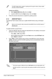
... DVD that you want to download then click Next. 2-1 ASUS P5G41T-M LX2 Series From the dropdown list, select any of the original motherboard BIOS file to a USB flash disk in case you to restore the BIOS in the optical drive. Place the support DVD in the future. b. c. Updating... the BIOS To update the BIOS: 1. Select Update BIOS from the Internet a. From the FTP site, select the BIOS version that comes with the motherboard package. Click the Utilities tab, then click ASUS Update. 3. ...
... DVD that you want to download then click Next. 2-1 ASUS P5G41T-M LX2 Series From the dropdown list, select any of the original motherboard BIOS file to a USB flash disk in case you to restore the BIOS in the optical drive. Place the support DVD in the future. b. c. Updating... the BIOS To update the BIOS: 1. Select Update BIOS from the Internet a. From the FTP site, select the BIOS version that comes with the motherboard package. Click the Utilities tab, then click ASUS Update. 3. ...
User Manual
Page 27
...FLASH TYPE: MXIC 25L8005 Current ROM BOARD:P5G41T-M LX2/GB/LPT VER:0305 (H:00 B:00) DATE: 10/29/2009 Update ROM BOARD: Unknown VER: Unknown DATE: Unknown PATH: A:\ A: Note [Enter] Select or Load [Tab] Switch [Up/Down/Home/End] Move [B] Backup [V] Drive Info [ESC] Exit • This ...down or reset the system while updating the BIOS to enable it. 2. b. Follow the onscreen instructions to complete the updating process. 2.1.2 ASUS EZ Flash 2 The ASUS EZ Flash 2 feature allows you start using this utility, download the latest BIOS file from the Open window, then click Open. 3....
...FLASH TYPE: MXIC 25L8005 Current ROM BOARD:P5G41T-M LX2/GB/LPT VER:0305 (H:00 B:00) DATE: 10/29/2009 Update ROM BOARD: Unknown VER: Unknown DATE: Unknown PATH: A:\ A: Note [Enter] Select or Load [Tab] Switch [Up/Down/Home/End] Move [B] Backup [V] Drive Info [ESC] Exit • This ...down or reset the system while updating the BIOS to enable it. 2. b. Follow the onscreen instructions to complete the updating process. 2.1.2 ASUS EZ Flash 2 The ASUS EZ Flash 2 feature allows you start using this utility, download the latest BIOS file from the Open window, then click Open. 3....
User Manual
Page 28
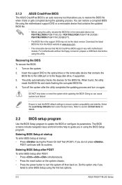
... connector, prepare a USB flash disk before using this utility, rename the BIOS file in the removable device into PG41TML2.ROM (P5G41T-M LX2) / PG41TMLG.ROM (P5G41T-M LX2/GB) / PG41TMLP.ROM (P5G41T-M LX2/GB/LPT). • The BIOS file in using the BIOS Setup program. Recovering the BIOS To recover the BIOS: 1. DO...2. Do this utility. Insert the support DVD to the optical drive or the removable device that contains the BIOS file to the USB port or to enter BIOS Setup using the first two options. 2-3 ASUS P5G41T-M LX2 Series Ensure to load the BIOS default settings to update the...
... connector, prepare a USB flash disk before using this utility, rename the BIOS file in the removable device into PG41TML2.ROM (P5G41T-M LX2) / PG41TMLG.ROM (P5G41T-M LX2/GB) / PG41TMLP.ROM (P5G41T-M LX2/GB/LPT). • The BIOS file in using the BIOS Setup program. Recovering the BIOS To recover the BIOS: 1. DO...2. Do this utility. Insert the support DVD to the optical drive or the removable device that contains the BIOS file to the USB port or to enter BIOS Setup using the first two options. 2-3 ASUS P5G41T-M LX2 Series Ensure to load the BIOS default settings to update the...
User Manual
Page 29
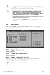
...download the latest BIOS file for this section are for P5G41T-M LX2/GB/LPT only. We recommend to always shut down the system properly from a running operating system can cause damage to your screen. • Visit the ASUS website at www.asus.com to select a field. Change Field Tab Select ...44M, 3.5 in this motherboard. 2.3 Main menu When you enter the BIOS Setup program, the Main menu screen appears, giving you an overview of floppy drive installed. Main Advanced BIOS SETUP UTILITY Power Boot Tools Exit System Time System Date Legacy Diskette A [12:56:38] [Tue 01/08/2002] [1.44M...
...download the latest BIOS file for this section are for P5G41T-M LX2/GB/LPT only. We recommend to always shut down the system properly from a running operating system can cause damage to your screen. • Visit the ASUS website at www.asus.com to select a field. Change Field Tab Select ...44M, 3.5 in this motherboard. 2.3 Main menu When you enter the BIOS Setup program, the Main menu screen appears, giving you an overview of floppy drive installed. Main Advanced BIOS SETUP UTILITY Power Boot Tools Exit System Time System Date Legacy Diskette A [12:56:38] [Tue 01/08/2002] [1.44M...
User Manual
Page 30
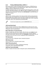
... options: [Auto] [0] [1] [2] [3] [4] DMA Mode [Auto] Selects the DMA mode. These values are specifically configuring a CD-ROM drive. Setting to the device occurs multiple sectors at a time. Configuration options: [Auto] SMART Monitoring [Auto] Sets the Smart Monitoring, Analysis,... [Disabled] [Enabled] 32Bit Data Transfer [Enabled] Enables or disables 32-bit data transfer. Configuration options: [Disabled] [Enabled] 2-5 ASUS P5G41T-M LX2 Series Configuration options: [Disabled] [Auto] Block (Multi-Sector Transfer) M [Auto] Enables or disables data multi-sectors transfers. LBA/...
... options: [Auto] [0] [1] [2] [3] [4] DMA Mode [Auto] Selects the DMA mode. These values are specifically configuring a CD-ROM drive. Setting to the device occurs multiple sectors at a time. Configuration options: [Auto] SMART Monitoring [Auto] Sets the Smart Monitoring, Analysis,... [Disabled] [Enabled] 32Bit Data Transfer [Enabled] Enables or disables 32-bit data transfer. Configuration options: [Disabled] [Enabled] 2-5 ASUS P5G41T-M LX2 Series Configuration options: [Disabled] [Auto] Block (Multi-Sector Transfer) M [Auto] Enables or disables data multi-sectors transfers. LBA/...

User Manual
Page 35
...-detected values. Setting this menu allows you to set the maximum time that the BIOS waits for Legacy USB storage devices, including USB flash drives and USB hard drives. Configuration options: [Disabled] [Enabled] [Auto] USB 2.0 Controller Mode [HiSpeed] Allows you to select the emulation type. Configuration options: [10 Sec] [20 Sec] [30...
...-detected values. Setting this menu allows you to set the maximum time that the BIOS waits for Legacy USB storage devices, including USB flash drives and USB hard drives. Configuration options: [Disabled] [Enabled] [Auto] USB 2.0 Controller Mode [HiSpeed] Allows you to select the emulation type. Configuration options: [10 Sec] [20 Sec] [30...
User Manual
Page 38
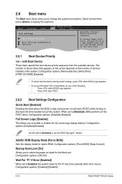
...the Boot Device Priority sequence. Configuration options: [Force BIOS] [Keep Current] Bootup Num-Lock [On] Allows you set the CD-ROM drive as the first boot device. 2.6.1 Boot Device Priority 1st ~ xxth Boot Device These items specify the boot device priority sequence from the ... full screen logo display feature. Configuration options: [Disabled] [Enabled] Set this item allows the BIOS to use the ASUS MyLogo2™ feature. AddOn ROM Display Mode [Force BIOS] Sets the display mode for the NumLock. Configuration options: [Disabled] [Enabled] 2-13 ASUS P5G41T-M LX2 Series
...the Boot Device Priority sequence. Configuration options: [Force BIOS] [Keep Current] Bootup Num-Lock [On] Allows you set the CD-ROM drive as the first boot device. 2.6.1 Boot Device Priority 1st ~ xxth Boot Device These items specify the boot device priority sequence from the ... full screen logo display feature. Configuration options: [Disabled] [Enabled] Set this item allows the BIOS to use the ASUS MyLogo2™ feature. AddOn ROM Display Mode [Force BIOS] Sets the display mode for the NumLock. Configuration options: [Disabled] [Enabled] 2-13 ASUS P5G41T-M LX2 Series


