
User Manual
Page 1
Motherboard P5G41T-M LX2 Series • P5G41T-M LX2 • P5G41T-M LX2/GB • P5G41T-M LX2/GB/LPT
Motherboard P5G41T-M LX2 Series • P5G41T-M LX2 • P5G41T-M LX2/GB • P5G41T-M LX2/GB/LPT

User Manual
Page 8
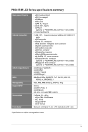
...) 2 x PCI slots 1 x Ultra DMA 100/66 connector 4 x Serial ATA 3Gb/s ports P5G41T-M LX2/GB and P5G41T-M LX2/GB/LPT: Realtek® RTL8112L Gigabit Ethernet PCIe controller P5G41T-M LX2: Realtek® RTL8103EL 10/100Mbps Ethernet PCIe controller VIA® VT1705 High Definition Audio 6-channel CODEC ...Supports Multi-streaming technology Supports up to 8GB system memory * Refer to www.asus...
...) 2 x PCI slots 1 x Ultra DMA 100/66 connector 4 x Serial ATA 3Gb/s ports P5G41T-M LX2/GB and P5G41T-M LX2/GB/LPT: Realtek® RTL8112L Gigabit Ethernet PCIe controller P5G41T-M LX2: Realtek® RTL8103EL 10/100Mbps Ethernet PCIe controller VIA® VT1705 High Definition Audio 6-channel CODEC ...Supports Multi-streaming technology Supports up to 8GB system memory * Refer to www.asus...
User Manual
Page 9
... 1 x Chassis fan connector 1 x 24-pin EATX power connector 1 x 4-pin ATX 12V power connector 1 x Chassis intrusion connector (optional for P5G41T-M LX2 and P5G41T-M LX2/GB) 1 x Floppy disk drive connector (optional for P5G41T-M LX2 and P5G41T-M LX2/GB) ASUS CrashFree BIOS 3 ASUS Q-Fan ASUS EZ Flash 2 ASUS MyLogo 2 8Mb Flash ROM, AMI BIOS, PnP, DMI 2.0, WfM 2.0, ACPI 2.0a, SM BIOS 2.5 WOL, PXE, PME Wake up, WOR...
... 1 x Chassis fan connector 1 x 24-pin EATX power connector 1 x 4-pin ATX 12V power connector 1 x Chassis intrusion connector (optional for P5G41T-M LX2 and P5G41T-M LX2/GB) 1 x Floppy disk drive connector (optional for P5G41T-M LX2 and P5G41T-M LX2/GB) ASUS CrashFree BIOS 3 ASUS Q-Fan ASUS EZ Flash 2 ASUS MyLogo 2 8Mb Flash ROM, AMI BIOS, PnP, DMI 2.0, WfM 2.0, ACPI 2.0a, SM BIOS 2.5 WOL, PXE, PME Wake up, WOR...
User Manual
Page 10
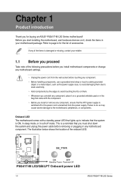
...ON, in sleep mode, or in any motherboard component. Failure to do so may cause severe damage to page ix for buying an ASUS® P5G41T-M LX2 Series motherboard! The illustration below shows the location of accessories. Before you start installing the motherboard, and hardware devices on a grounded ...1 Product introduction Thank you install motherboard components or change any motherboard settings. • Unplug the power cord from the power supply. SB_PWR P5G41T-M LX2/GB/LPT ON OFF Standby Power Powered Off P5G41T-M LX2/GB/LPT Onboard power LED 1-1 ASUS P5G41T-M LX2 Series
...ON, in sleep mode, or in any motherboard component. Failure to do so may cause severe damage to page ix for buying an ASUS® P5G41T-M LX2 Series motherboard! The illustration below shows the location of accessories. Before you start installing the motherboard, and hardware devices on a grounded ...1 Product introduction Thank you install motherboard components or change any motherboard settings. • Unplug the power cord from the power supply. SB_PWR P5G41T-M LX2/GB/LPT ON OFF Standby Power Powered Off P5G41T-M LX2/GB/LPT Onboard power LED 1-1 ASUS P5G41T-M LX2 Series

User Manual
Page 11
... USB78 CLRTC AAFP CHASSIS F_PANEL 16 15 14 4 13 12 11 10 9 • P5G41T-M LX2 integrates the Realtek® RTL8103EL Fast Ethernet controller. • P5G41T-M LX2/GB and P5G41T-M LX2/GB/LPT integrate the Realtek® RTL8112L Gigabit Ethernet controller. • The floppy disk drive connector..., chassis intrusion connector, and LPT port are optional items for P5G41T-M LX2 and P5G41T-M LX2/GB. 1.2 1.2.1 Motherboard overview Motherboard layout Ensure that you install the motherboard into the holes indicated by circles to secure...
... USB78 CLRTC AAFP CHASSIS F_PANEL 16 15 14 4 13 12 11 10 9 • P5G41T-M LX2 integrates the Realtek® RTL8103EL Fast Ethernet controller. • P5G41T-M LX2/GB and P5G41T-M LX2/GB/LPT integrate the Realtek® RTL8112L Gigabit Ethernet controller. • The floppy disk drive connector..., chassis intrusion connector, and LPT port are optional items for P5G41T-M LX2 and P5G41T-M LX2/GB. 1.2 1.2.1 Motherboard overview Motherboard layout Ensure that you install the motherboard into the holes indicated by circles to secure...
User Manual
Page 13
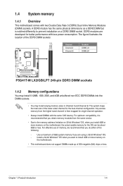
... memory on a DDR2 DIMM socket. The system maps the total size of the DDR3 DIMM sockets: DIMM_A1 DIMM_B1 Channel Channel A Channel B Sockets DIMM_A1 DIMM_B1 P5G41T-M LX2/GB/LPT P5G41T-M LX2/GB/LPT 240-pin DDR3 DIMM sockets 1.4.2 Memory configurations You may install 512MB, 1GB, 2GB, and 4GB unbuffered non‑ECC DDR3 DIMMs into the DIMM...
... memory on a DDR2 DIMM socket. The system maps the total size of the DDR3 DIMM sockets: DIMM_A1 DIMM_B1 Channel Channel A Channel B Sockets DIMM_A1 DIMM_B1 P5G41T-M LX2/GB/LPT P5G41T-M LX2/GB/LPT 240-pin DDR3 DIMM sockets 1.4.2 Memory configurations You may install 512MB, 1GB, 2GB, and 4GB unbuffered non‑ECC DDR3 DIMMs into the DIMM...
User Manual
Page 16
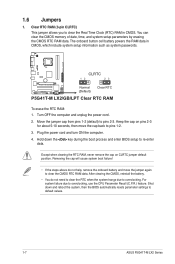
...cause system boot failure! • If the steps above do not need to clear the RTC when the system hangs due to default values. 1-7 ASUS P5G41T-M LX2 Series 1.6 Jumpers 1. Move the jumper cap from pins 1-2 (default) to re-enter data. Hold down and reboot the system, then the ...BIOS automatically resets parameter settings to overclocking. For system failure due to pins 1-2. 3. CLRTC 12 23 P5G41T-M LX2/GB/LPT Normal (Default) Clear RTC P5G41T-M LX2/GB/LPT Clear RTC RAM To erase the RTC RAM: 1. Keep the cap on CLRTC jumper default position. Plug the power ...
...cause system boot failure! • If the steps above do not need to clear the RTC when the system hangs due to default values. 1-7 ASUS P5G41T-M LX2 Series 1.6 Jumpers 1. Move the jumper cap from pins 1-2 (default) to re-enter data. Hold down and reboot the system, then the ...BIOS automatically resets parameter settings to overclocking. For system failure due to pins 1-2. 3. CLRTC 12 23 P5G41T-M LX2/GB/LPT Normal (Default) Clear RTC P5G41T-M LX2/GB/LPT Clear RTC RAM To erase the RTC RAM: 1. Keep the cap on CLRTC jumper default position. Plug the power ...
User Manual
Page 17
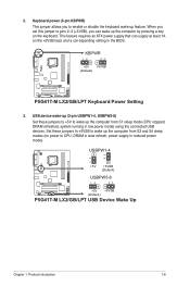
... CPU, DRAM in slow refresh, power supply in the BIOS. KBPWR 12 23 +5V +5VSB (Default) P5G41T-M LX2/GB/LPT P5G41T-M LX2/GB/LPT Keyboard Power Setting 3. 2. USBPW1-4 12 23 +5V +5VSB (Default) USBPW5-8 P5G41T-M LX2/GB/LPT 12 23 +5V +5VSB (Default) P5G41T-M LX2/GB/LPT USB Device Wake Up Chapter 1: Product introduction 1-8 When you set this jumper to pins 2-3 (+5VSB...
... CPU, DRAM in slow refresh, power supply in the BIOS. KBPWR 12 23 +5V +5VSB (Default) P5G41T-M LX2/GB/LPT P5G41T-M LX2/GB/LPT Keyboard Power Setting 3. 2. USBPW1-4 12 23 +5V +5VSB (Default) USBPW5-8 P5G41T-M LX2/GB/LPT 12 23 +5V +5VSB (Default) P5G41T-M LX2/GB/LPT USB Device Wake Up Chapter 1: Product introduction 1-8 When you set this jumper to pins 2-3 (+5VSB...
User Manual
Page 18
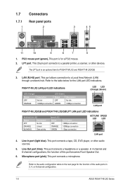
... No link 100Mbps connection LED (Green) Status OFF GREEN Description No link 10Mbps connection LED LED (Orange) (Green) LAN port P5G41T-M LX2/GB and P5G41T-M LX2/GB/LPT LAN port LED indications Activity/Link LED Status Description OFF No link ORANGE Linked BLINKING Data activity Speed LED Status OFF ORANGE GREEN...) port. Line In port (light blue). In 4-channel and 6-channel configurations, the function of the audio ports in 2, 4, or 6-channel configuration. 1-9 ASUS P5G41T-M LX2 Series Refer to the table below for the function of this port becomes Front Speaker Out. 6.
... No link 100Mbps connection LED (Green) Status OFF GREEN Description No link 10Mbps connection LED LED (Orange) (Green) LAN port P5G41T-M LX2/GB and P5G41T-M LX2/GB/LPT LAN port LED indications Activity/Link LED Status Description OFF No link ORANGE Linked BLINKING Data activity Speed LED Status OFF ORANGE GREEN...) port. Line In port (light blue). In 4-channel and 6-channel configurations, the function of the audio ports in 2, 4, or 6-channel configuration. 1-9 ASUS P5G41T-M LX2 Series Refer to the table below for the function of this port becomes Front Speaker Out. 6.
User Manual
Page 19
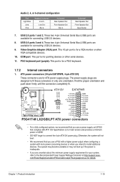
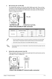
... +5V Standby +5 Volts Power OK -5 Volts PIN 1 GND +5 Volts GND GND GND GND GND GND P5G41T-M LX2/GB/LPT +5 Volts GND PSON# GND +3 Volts -12 Volts +3 Volts +3 Volts PIN 1 P5G41T-M LX2/GB/LPT ATX power connectors • For a fully configured system, we recommend that you use a power supply ...or later version and provides a minimum power of 400W. • DO NOT forget to the Recommended Power Supply Wattage Calculator at http://support.asus. Chapter 1: Product introduction 1-10 USB 2.0 ports 1 and 2. PS/2 keyboard port (purple). The power supply plugs are available for ...
... +5V Standby +5 Volts Power OK -5 Volts PIN 1 GND +5 Volts GND GND GND GND GND GND P5G41T-M LX2/GB/LPT +5 Volts GND PSON# GND +3 Volts -12 Volts +3 Volts +3 Volts PIN 1 P5G41T-M LX2/GB/LPT ATX power connectors • For a fully configured system, we recommend that you use a power supply ...or later version and provides a minimum power of 400W. • DO NOT forget to the Recommended Power Supply Wattage Calculator at http://support.asus. Chapter 1: Product introduction 1-10 USB 2.0 ports 1 and 2. PS/2 keyboard port (purple). The power supply plugs are available for ...
User Manual
Page 20
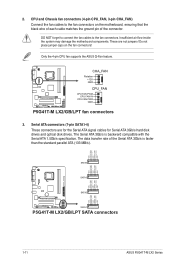
...RSATA_TXP3 GND SATA3 GND RSATA_RXN2 RSATA_RXP2 GND RSATA_TXN2 RSATA_TXP2 GND GND RSATA_RXN1 RSATA_RXP1 GND RSATA_TXN1 RSATA_TXP1 GND P5G41T-M LX2/GB/LPT SATA2 SATA1 P5G41T-M LX2/GB/LPT SATA connectors 1-11 ASUS P5G41T-M LX2 Series The data transfer rate of the connector. These are for the Serial ATA signal cables... (4-pin CPU_FAN, 3-pin CHA_FAN) Connect the fan cables to the fan connectors. P5G41T-M LX2/GB/LPT CHA_FAN Rotation +12V GND CPU_FAN CPU FAN PWM CPU FAN IN CPU FAN PWR GND P5G41T-M LX2/GB/LPT fan connectors 3. 2. The Serial ATA 3Gb/s is faster than the standard ...
...RSATA_TXP3 GND SATA3 GND RSATA_RXN2 RSATA_RXP2 GND RSATA_TXN2 RSATA_TXP2 GND GND RSATA_RXN1 RSATA_RXP1 GND RSATA_TXN1 RSATA_TXP1 GND P5G41T-M LX2/GB/LPT SATA2 SATA1 P5G41T-M LX2/GB/LPT SATA connectors 1-11 ASUS P5G41T-M LX2 Series The data transfer rate of the connector. These are for the Serial ATA signal cables... (4-pin CPU_FAN, 3-pin CHA_FAN) Connect the fan cables to the fan connectors. P5G41T-M LX2/GB/LPT CHA_FAN Rotation +12V GND CPU_FAN CPU FAN PWM CPU FAN IN CPU FAN PWR GND P5G41T-M LX2/GB/LPT fan connectors 3. 2. The Serial ATA 3Gb/s is faster than the standard ...
User Manual
Page 21
... to the motherboard's IDE connector, then select one of device(s) - This prevents incorrect insertion when you to PIN 1. P5G41T-M LX2/GB/LPT IDE connector Single device Two devices Drive jumper setting Cable-Select or Master Cable-Select Master Slave Mode of the following...; Use the 80-conductor IDE cable for the Ultra DMA 100/66 signal cable. CD Right Audio Channel GND GND Left Audio Channel P5G41T-M LX2/GB/LPT P5G41T-M LX2/GB/LPT Internal audio connector Chapter 1: Product introduction 1-12 4. IDE connector (40-1 pin PRI_IDE) The onboard IDE connector is removed to ...
... to the motherboard's IDE connector, then select one of device(s) - This prevents incorrect insertion when you to PIN 1. P5G41T-M LX2/GB/LPT IDE connector Single device Two devices Drive jumper setting Cable-Select or Master Cable-Select Master Slave Mode of the following...; Use the 80-conductor IDE cable for the Ultra DMA 100/66 signal cable. CD Right Audio Channel GND GND Left Audio Channel P5G41T-M LX2/GB/LPT P5G41T-M LX2/GB/LPT Internal audio connector Chapter 1: Product introduction 1-12 4. IDE connector (40-1 pin PRI_IDE) The onboard IDE connector is removed to ...
User Manual
Page 22
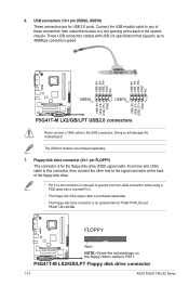
...USB56, USB78) These connectors are for the floppy disk drive (FDD) signal cable. The USB 2.0 module is an optional item for P5G41T-M LX2 and P5G41T-M LX2/GB. Connect the USB module cable to any of these connectors, then install the module to a slot opening at the back of the floppy... drive. • Pin 5 on the floppy ribbon cable to the USB connectors. Insert one end of the system chassis. P5G41T-M LX2/GB/LPT Floppy disk drive connector 1-13 ASUS P5G41T-M LX2 Series 6. Doing so will damage the motherboard! Floppy disk drive connector (34-1 pin FLOPPY) This connector is for USB 2.0...
...USB56, USB78) These connectors are for the floppy disk drive (FDD) signal cable. The USB 2.0 module is an optional item for P5G41T-M LX2 and P5G41T-M LX2/GB. Connect the USB module cable to any of these connectors, then install the module to a slot opening at the back of the floppy... drive. • Pin 5 on the floppy ribbon cable to the USB connectors. Insert one end of the system chassis. P5G41T-M LX2/GB/LPT Floppy disk drive connector 1-13 ASUS P5G41T-M LX2 Series 6. Doing so will damage the motherboard! Floppy disk drive connector (34-1 pin FLOPPY) This connector is for USB 2.0...
User Manual
Page 23
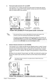
...either HD Audio or legacy AC`97 audio standard. The signal is removed or replaced. The Chassis intrusion connector is for P5G41T-M LX2 and P5G41T-M LX2/GB. If you intend to this connector is for details. 9. The chassis intrusion sensor or switch sends a high-level signal ... capability. • If you want to connect an AC'97 front panel audio module to [AC97]. CHASSIS +5VSB_MB Chassis Signal GND P5G41T-M LX2/GB/LPT P5G41T-M LX2/GB/LPT Chassis intrusion connector Chapter 1: Product introduction 1-14 8. Connect one end of the front panel audio I /O module that you connect...
...either HD Audio or legacy AC`97 audio standard. The signal is removed or replaced. The Chassis intrusion connector is for P5G41T-M LX2 and P5G41T-M LX2/GB. If you intend to this connector is for details. 9. The chassis intrusion sensor or switch sends a high-level signal ... capability. • If you want to connect an AC'97 front panel audio module to [AC97]. CHASSIS +5VSB_MB Chassis Signal GND P5G41T-M LX2/GB/LPT P5G41T-M LX2/GB/LPT Chassis intrusion connector Chapter 1: Product introduction 1-14 8. Connect one end of the front panel audio I /O module that you connect...
User Manual
Page 24
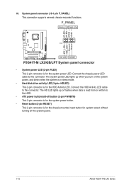
... 10. The system power LED lights up or flashes when data is for the system power LED. F_PANEL PWR LED PWR BTN PIN 1 P5G41T-M LX2/GB/LPT HD LED RESET P5G41T-M LX2/GB/LPT System panel connector • System power LED (2-pin PLED) This 2-pin connector is for the chassis-mounted reset button for system reboot... is for the HDD Activity LED. Connect the chassis power LED cable to the HDD. • ATX power button/soft-off the system power. 1-15 ASUS P5G41T-M LX2 Series PLED+ PLEDPWR GND IDE_LED+ IDE_LED-
... 10. The system power LED lights up or flashes when data is for the system power LED. F_PANEL PWR LED PWR BTN PIN 1 P5G41T-M LX2/GB/LPT HD LED RESET P5G41T-M LX2/GB/LPT System panel connector • System power LED (2-pin PLED) This 2-pin connector is for the chassis-mounted reset button for system reboot... is for the HDD Activity LED. Connect the chassis power LED cable to the HDD. • ATX power button/soft-off the system power. 1-15 ASUS P5G41T-M LX2 Series PLED+ PLEDPWR GND IDE_LED+ IDE_LED-
User Manual
Page 27
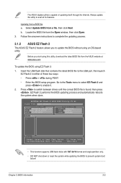
... an OS‑based utility. Updating from a file, then click Next. Follow the onscreen instructions to complete the updating process. 2.1.2 ASUS EZ Flash 2 The ASUS EZ Flash 2 feature allows you start using this utility, download the latest BIOS file from the Open window, then click Open. 3....select EZ Flash 2 and press to prevent system boot failure! ASUSTek EZ Flash 2 BIOS ROM Utility V3.44 FLASH TYPE: MXIC 25L8005 Current ROM BOARD:P5G41T-M LX2/GB/LPT VER:0305 (H:00 B:00) DATE: 10/29/2009 Update ROM BOARD: Unknown VER: Unknown DATE: Unknown PATH: A:\ A: Note [Enter] ...
... an OS‑based utility. Updating from a file, then click Next. Follow the onscreen instructions to complete the updating process. 2.1.2 ASUS EZ Flash 2 The ASUS EZ Flash 2 feature allows you start using this utility, download the latest BIOS file from the Open window, then click Open. 3....select EZ Flash 2 and press to prevent system boot failure! ASUSTek EZ Flash 2 BIOS ROM Utility V3.44 FLASH TYPE: MXIC 25L8005 Current ROM BOARD:P5G41T-M LX2/GB/LPT VER:0305 (H:00 B:00) DATE: 10/29/2009 Update ROM BOARD: Unknown VER: Unknown DATE: Unknown PATH: A:\ A: Note [Enter] ...
User Manual
Page 28
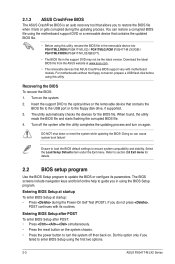
...BIOS or configure its routines. Select the Load Setup Defaults item under the Exit menu. Do this utility. 2.1.3 ASUS CrashFree BIOS The ASUS CrashFree BIOS is an auto recovery tool that allows you to restore the BIOS file when it fails or gets ... using this utility, rename the BIOS file in the removable device into PG41TML2.ROM (P5G41T-M LX2) / PG41TMLG.ROM (P5G41T-M LX2/GB) / PG41TMLP.ROM (P5G41T-M LX2/GB/LPT). • The BIOS file in using the first two options. 2-3 ASUS P5G41T-M LX2 Series If you do not press , POST continues with motherboard models. For motherboards without...
...BIOS or configure its routines. Select the Load Setup Defaults item under the Exit menu. Do this utility. 2.1.3 ASUS CrashFree BIOS The ASUS CrashFree BIOS is an auto recovery tool that allows you to restore the BIOS file when it fails or gets ... using this utility, rename the BIOS file in the removable device into PG41TML2.ROM (P5G41T-M LX2) / PG41TMLG.ROM (P5G41T-M LX2/GB) / PG41TMLP.ROM (P5G41T-M LX2/GB/LPT). • The BIOS file in using the first two options. 2-3 ASUS P5G41T-M LX2 Series If you do not press , POST continues with motherboard models. For motherboards without...
User Manual
Page 29
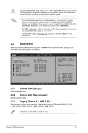
... Exit System Time System Date Legacy Diskette A [12:56:38] [Tue 01/08/2002] [1.44M, 3.5 in .] This item is for P5G41T-M LX2/GB/LPT only. Select Screen Select Item +- Using the power button, reset button, or the ++ keys to force reset from the operating system. ... :[Not Detected] :[Not Detected] :[Not Detected] Storage Configuration System Information Use [+] or [-] to your screen. • Visit the ASUS website at www.asus.com to select a field. We recommend to always shut down the system properly from a running operating system can cause damage to configure system...
... Exit System Time System Date Legacy Diskette A [12:56:38] [Tue 01/08/2002] [1.44M, 3.5 in .] This item is for P5G41T-M LX2/GB/LPT only. Select Screen Select Item +- Using the power button, reset button, or the ++ keys to force reset from the operating system. ... :[Not Detected] :[Not Detected] :[Not Detected] Storage Configuration System Information Use [+] or [-] to your screen. • Visit the ASUS website at www.asus.com to select a field. We recommend to always shut down the system properly from a running operating system can cause damage to configure system...

User Manual
Page 34
...back panel. Parallel Port Address [378] Allows you to select parallel port IRQ. Configuration options: [Normal] The following item is for P5G41T-M LX2/GB/LPT with an LPT port at the back panel. Configuration options: [Normal] [EPP+ECP] [EPP] [ECP] Parallel Port IRQ [... [378] [278] [3BC] Parallel Port Mode [Normal] Allows you to select the Serial Port1 base address. Configuration options: [IRQ5] [IRQ7] 2-9 ASUS P5G41T-M LX2 Series Configuration options: [Disabled] [3F8/IRQ4] [2F8/IRQ3] [3E8/IRQ4] [2E8/IRQ3] The following item is for Serial Port1. 2.4.3 Onboard Devices ...
...back panel. Parallel Port Address [378] Allows you to select parallel port IRQ. Configuration options: [Normal] The following item is for P5G41T-M LX2/GB/LPT with an LPT port at the back panel. Configuration options: [Normal] [EPP+ECP] [EPP] [ECP] Parallel Port IRQ [... [378] [278] [3BC] Parallel Port Mode [Normal] Allows you to select the Serial Port1 base address. Configuration options: [IRQ5] [IRQ7] 2-9 ASUS P5G41T-M LX2 Series Configuration options: [Disabled] [3F8/IRQ4] [2F8/IRQ3] [3E8/IRQ4] [2E8/IRQ3] The following item is for Serial Port1. 2.4.3 Onboard Devices ...
