
User Manual
Page 3
Contents Notices...v Safety information vi About this guide vi P5G41T-M LX2 Series specifications summary viii Chapter 1: Product introduction 1.1 Before you proceed 1-1 1.2 Motherboard overview 1-2 1.2.1 Motherboard layout 1-2 ...10 1.8 Software support 1-16 1.8.1 Installing an operating system 1-16 1.8.2 Support DVD information 1-16 Chapter 2: BIOS information 2.1 Managing and updating your BIOS 2-1 2.1.1 ASUS Update utility 2-1 2.1.2 ASUS EZ Flash 2 2-2 2.1.3 ASUS CrashFree BIOS 2-3 2.2 BIOS setup program 2-3 2.3 Main menu 2-4 2.3.1 System Time 2-4 2.3.2 System Date 2-4 iii
Contents Notices...v Safety information vi About this guide vi P5G41T-M LX2 Series specifications summary viii Chapter 1: Product introduction 1.1 Before you proceed 1-1 1.2 Motherboard overview 1-2 1.2.1 Motherboard layout 1-2 ...10 1.8 Software support 1-16 1.8.1 Installing an operating system 1-16 1.8.2 Support DVD information 1-16 Chapter 2: BIOS information 2.1 Managing and updating your BIOS 2-1 2.1.1 ASUS Update utility 2-1 2.1.2 ASUS EZ Flash 2 2-2 2.1.3 ASUS CrashFree BIOS 2-3 2.2 BIOS setup program 2-3 2.3 Main menu 2-4 2.3.1 System Time 2-4 2.3.2 System Date 2-4 iii

User Manual
Page 6
...If the power supply is broken, do not try to fix it supports. • Chapter 2: BIOS information This chapter tells how to change system settings through the BIOS Setup menus. These devices could interrupt the grounding circuit. • Ensure that all power cables from ... your power supply is organized This guide contains the following parts: • Chapter 1: Product introduction This chapter describes the features of the BIOS parameters are unplugged. • Seek professional assistance before using , contact your dealer immediately. • To avoid short circuits, keep paper ...
...If the power supply is broken, do not try to fix it supports. • Chapter 2: BIOS information This chapter tells how to change system settings through the BIOS Setup menus. These devices could interrupt the grounding circuit. • Ensure that all power cables from ... your power supply is organized This guide contains the following parts: • Chapter 1: Product introduction This chapter describes the features of the BIOS parameters are unplugged. • Seek professional assistance before using , contact your dealer immediately. • To avoid short circuits, keep paper ...
User Manual
Page 9
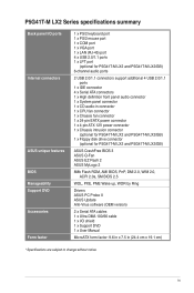
... 12V power connector 1 x Chassis intrusion connector (optional for P5G41T-M LX2 and P5G41T-M LX2/GB) 1 x Floppy disk drive connector (optional for P5G41T-M LX2 and P5G41T-M LX2/GB) ASUS CrashFree BIOS 3 ASUS Q-Fan ASUS EZ Flash 2 ASUS MyLogo 2 8Mb Flash ROM, AMI BIOS, PnP, DMI 2.0, WfM 2.0, ACPI 2.0a, SM BIOS 2.5 WOL, PXE, PME Wake up, WOR by Ring Drivers ASUS PC Probe II ASUS Update Anti-Virus software (OEM version) 2 x Serial...
... 12V power connector 1 x Chassis intrusion connector (optional for P5G41T-M LX2 and P5G41T-M LX2/GB) 1 x Floppy disk drive connector (optional for P5G41T-M LX2 and P5G41T-M LX2/GB) ASUS CrashFree BIOS 3 ASUS Q-Fan ASUS EZ Flash 2 ASUS MyLogo 2 8Mb Flash ROM, AMI BIOS, PnP, DMI 2.0, WfM 2.0, ACPI 2.0a, SM BIOS 2.5 WOL, PXE, PME Wake up, WOR by Ring Drivers ASUS PC Probe II ASUS Update Anti-Virus software (OEM version) 2 x Serial...

User Manual
Page 11
... introduction 1-2 AUDIO RTL 8112L ICS 9LPRS441 Intel® G41 Lithium Cell CMOS Power PRI_IDE 7 2 24.4cm(9.6in) EATXPWR Super PCIEX16 I/O 17 P5G41T-M LX2/GB/LPT SATA4 SATA3 8Mb PCI1 Intel® SATA2 BIOS SATA1 ICH7 PCI2 8 VIA VT1705 CD FLOPPY SB_PWR USBPW5-8 USB56 USB78 CLRTC AAFP CHASSIS F_PANEL 16 15 14 4 13 12 11...
... introduction 1-2 AUDIO RTL 8112L ICS 9LPRS441 Intel® G41 Lithium Cell CMOS Power PRI_IDE 7 2 24.4cm(9.6in) EATXPWR Super PCIEX16 I/O 17 P5G41T-M LX2/GB/LPT SATA4 SATA3 8Mb PCI1 Intel® SATA2 BIOS SATA1 ICH7 PCI2 8 VIA VT1705 CD FLOPPY SB_PWR USBPW5-8 USB56 USB78 CLRTC AAFP CHASSIS F_PANEL 16 15 14 4 13 12 11...

User Manual
Page 14
... Motherboard Qualified Vendors Lists (QVL) DDR3-1066MHz capability Vendor Part No. Visit the ASUS website at www.asus.com for the latest QVL. 1-5 ASUS P5G41T-M LX2 Series Timing Dimm (Bios) Voltage Crucial CT12864BA1067.8FF 1024MB SS Crucial CT25664BA1067.16FF 2048MB DS Elpida EBJ51UD8BAFA-AC-E 512MB SS Elpida EBJ51UD8BAFA-AE-E 512MB SS Elpida EBJ11UD8BAFA-AE-E 1024MB ...
... Motherboard Qualified Vendors Lists (QVL) DDR3-1066MHz capability Vendor Part No. Visit the ASUS website at www.asus.com for the latest QVL. 1-5 ASUS P5G41T-M LX2 Series Timing Dimm (Bios) Voltage Crucial CT12864BA1067.8FF 1024MB SS Crucial CT25664BA1067.16FF 2048MB DS Elpida EBJ51UD8BAFA-AC-E 512MB SS Elpida EBJ51UD8BAFA-AE-E 512MB SS Elpida EBJ11UD8BAFA-AE-E 1024MB ...
User Manual
Page 15
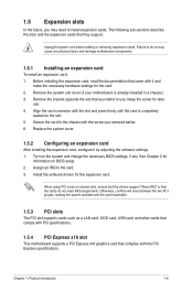
Align the card connector with the PCI Express specifications. See Chapter 2 for later use . When using PCI cards on BIOS setup. 2. Otherwise, conflicts will arise between the two PCI groups, making the system unstable and the card inoperable. 1.5.3 PCI slots The PCI slot supports cards .... 2. Secure the card to install expansion cards. Remove the system unit cover (if your motherboard is completely seated on the system and change the necessary BIOS settings, if any.
Align the card connector with the PCI Express specifications. See Chapter 2 for later use . When using PCI cards on BIOS setup. 2. Otherwise, conflicts will arise between the two PCI groups, making the system unstable and the card inoperable. 1.5.3 PCI slots The PCI slot supports cards .... 2. Secure the card to install expansion cards. Remove the system unit cover (if your motherboard is completely seated on the system and change the necessary BIOS settings, if any.
User Manual
Page 16
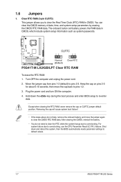
... can clear the CMOS memory of date, time, and system setup parameters by erasing the CMOS RTC RAM data. CLRTC 12 23 P5G41T-M LX2/GB/LPT Normal (Default) Clear RTC P5G41T-M LX2/GB/LPT Clear RTC RAM To erase the RTC RAM: 1. Turn OFF the computer and unplug the power cord. 2. After clearing the...not need to clear the RTC when the system hangs due to default values. 1-7 ASUS P5G41T-M LX2 Series Plug the power cord and turn ON the computer. 4. Shut down the key during the boot process and enter BIOS setup to clear the CMOS RTC RAM data. 1.6 Jumpers 1. The onboard button ...
... can clear the CMOS memory of date, time, and system setup parameters by erasing the CMOS RTC RAM data. CLRTC 12 23 P5G41T-M LX2/GB/LPT Normal (Default) Clear RTC P5G41T-M LX2/GB/LPT Clear RTC RAM To erase the RTC RAM: 1. Turn OFF the computer and unplug the power cord. 2. After clearing the...not need to clear the RTC when the system hangs due to default values. 1-7 ASUS P5G41T-M LX2 Series Plug the power cord and turn ON the computer. 4. Shut down the key during the boot process and enter BIOS setup to clear the CMOS RTC RAM data. 1.6 Jumpers 1. The onboard button ...
User Manual
Page 17
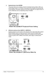
... pressing a key on the +5VSB lead, and a corresponding setting in the BIOS. USBPW1-4 12 23 +5V +5VSB (Default) USBPW5-8 P5G41T-M LX2/GB/LPT 12 23 +5V +5VSB (Default) P5G41T-M LX2/GB/LPT USB Device Wake Up Chapter 1: Product introduction 1-8 KBPWR 12 23 +5V +5VSB (Default) P5G41T-M LX2/GB/LPT P5G41T-M LX2/GB/LPT Keyboard Power Setting 3. 2. Keyboard power (3-pin KBPWR) This jumper allows...
... pressing a key on the +5VSB lead, and a corresponding setting in the BIOS. USBPW1-4 12 23 +5V +5VSB (Default) USBPW5-8 P5G41T-M LX2/GB/LPT 12 23 +5V +5VSB (Default) P5G41T-M LX2/GB/LPT USB Device Wake Up Chapter 1: Product introduction 1-8 KBPWR 12 23 +5V +5VSB (Default) P5G41T-M LX2/GB/LPT P5G41T-M LX2/GB/LPT Keyboard Power Setting 3. 2. Keyboard power (3-pin KBPWR) This jumper allows...
User Manual
Page 23
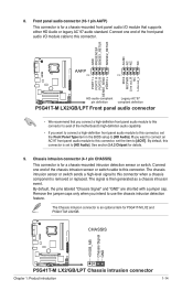
... you intend to use the chassis intrusion detection feature. By default, this connector is for P5G41T-M LX2 and P5G41T-M LX2/GB. Chassis intrusion connector (4-1 pin CHASSIS) This connector is set to this connector, set the Front Panel Type item in the BIOS setup to [AC97]. Connect one end of the motherboard's high-definition audio capability. •...
... you intend to use the chassis intrusion detection feature. By default, this connector is for P5G41T-M LX2 and P5G41T-M LX2/GB. Chassis intrusion connector (4-1 pin CHASSIS) This connector is set to this connector, set the Front Panel Type item in the BIOS setup to [AC97]. Connect one end of the motherboard's high-definition audio capability. •...
User Manual
Page 26
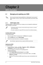
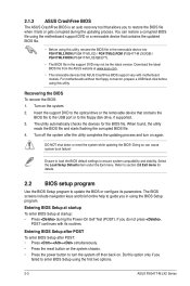
...Auto Select then click Next. Select the ASUS FTP site nearest you to download then click Next. 2-1 ASUS P5G41T-M LX2 Series The Drivers menu appears. 2. b. c. Follow the onscreen instructions to restore the BIOS in the optical drive. Place the ...support DVD in the future. Updating the BIOS To update the BIOS: 1. Select Update BIOS from the Internet a. Chapter 2 BIOS information 2.1 Managing and updating your BIOS...
...Auto Select then click Next. Select the ASUS FTP site nearest you to download then click Next. 2-1 ASUS P5G41T-M LX2 Series The Drivers menu appears. 2. b. c. Follow the onscreen instructions to restore the BIOS in the optical drive. Place the ...support DVD in the future. Updating the BIOS To update the BIOS: 1. Select Update BIOS from the Internet a. Chapter 2 BIOS information 2.1 Managing and updating your BIOS...
User Manual
Page 27
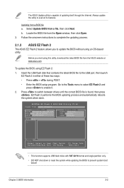
... Go to the Tools menu to select EZ Flash 2 and press to prevent system boot failure! ASUSTek EZ Flash 2 BIOS ROM Utility V3.44 FLASH TYPE: MXIC 25L8005 Current ROM BOARD:P5G41T-M LX2/GB/LPT VER:0305 (H:00 B:00) DATE: 10/29/2009 Update ROM BOARD: Unknown VER: Unknown DATE: Unknown PATH:...partition only. • DO NOT shut down or reset the system while updating the BIOS to enable it. 2. Updating from the ASUS website at www.asus.com. Press to complete the updating process. 2.1.2 ASUS EZ Flash 2 The ASUS EZ Flash 2 feature allows you start using EZ Flash 2: 1. Always update the...
... Go to the Tools menu to select EZ Flash 2 and press to prevent system boot failure! ASUSTek EZ Flash 2 BIOS ROM Utility V3.44 FLASH TYPE: MXIC 25L8005 Current ROM BOARD:P5G41T-M LX2/GB/LPT VER:0305 (H:00 B:00) DATE: 10/29/2009 Update ROM BOARD: Unknown VER: Unknown DATE: Unknown PATH:...partition only. • DO NOT shut down or reset the system while updating the BIOS to enable it. 2. Updating from the ASUS website at www.asus.com. Press to complete the updating process. 2.1.2 ASUS EZ Flash 2 The ASUS EZ Flash 2 feature allows you start using EZ Flash 2: 1. Always update the...
User Manual
Page 28
... the Power-On Self Test (POST). If you to enter BIOS Setup using this utility, rename the BIOS file in the removable device into PG41TML2.ROM (P5G41T-M LX2) / PG41TMLG.ROM (P5G41T-M LX2/GB) / PG41TMLP.ROM (P5G41T-M LX2/GB/LPT). • The BIOS file in using the BIOS Setup program. 2.1.3 ASUS CrashFree BIOS The ASUS CrashFree BIOS is an auto recovery tool that allows you do not...
... the Power-On Self Test (POST). If you to enter BIOS Setup using this utility, rename the BIOS file in the removable device into PG41TML2.ROM (P5G41T-M LX2) / PG41TMLG.ROM (P5G41T-M LX2/GB) / PG41TMLP.ROM (P5G41T-M LX2/GB/LPT). • The BIOS file in using the BIOS Setup program. 2.1.3 ASUS CrashFree BIOS The ASUS CrashFree BIOS is an auto recovery tool that allows you do not...
User Manual
Page 29
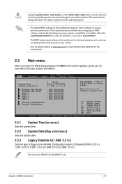
...Date [Day xx/xx/xxxx] Sets the system date. 2.3.3 Legacy Diskette A [1.44M, 3.5 in .] This item is for P5G41T-M LX2/GB/LPT only. If the system becomes unstable after changing any BIOS settings, load the default settings to configure system time. Using the power button, reset button, or the ++ keys to force... reset from the operating system. • The default BIOS settings for this motherboard apply for most conditions to your screen. • Visit the ASUS website at www.asus.com to select a field. Select the Load Setups Default item under the Exit Menu. We...
...Date [Day xx/xx/xxxx] Sets the system date. 2.3.3 Legacy Diskette A [1.44M, 3.5 in .] This item is for P5G41T-M LX2/GB/LPT only. If the system becomes unstable after changing any BIOS settings, load the default settings to configure system time. Using the power button, reset button, or the ++ keys to force... reset from the operating system. • The default BIOS settings for this motherboard apply for most conditions to your screen. • Visit the ASUS website at www.asus.com to select a field. Select the Load Setups Default item under the Exit Menu. We...
User Manual
Page 30
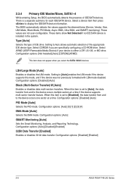
...PIO mode. Configuration options: [Auto] [Disabled] [Enabled] 32Bit Data Transfer [Enabled] Enables or disables 32-bit data transfer. The BIOS automatically detects the values opposite the dimmed items (Device, Vendor, Size, LBA Mode, Block Mode, PIO Mode, Async DMA, Ultra ...Not Installed] [Auto] [CDROM] [ARMD] This item does not appear when you are not user-configurable. Configuration options: [Disabled] [Enabled] 2-5 ASUS P5G41T-M LX2 Series Setting to display the IDE/SATA device information. Configuration options: [Auto] [0] [1] [2] [3] [4] DMA Mode [Auto] Selects the DMA mode. ...
...PIO mode. Configuration options: [Auto] [Disabled] [Enabled] 32Bit Data Transfer [Enabled] Enables or disables 32-bit data transfer. The BIOS automatically detects the values opposite the dimmed items (Device, Vendor, Size, LBA Mode, Block Mode, PIO Mode, Async DMA, Ultra ...Not Installed] [Auto] [CDROM] [ARMD] This item does not appear when you are not user-configurable. Configuration options: [Disabled] [Enabled] 2-5 ASUS P5G41T-M LX2 Series Setting to display the IDE/SATA device information. Configuration options: [Auto] [0] [1] [2] [3] [4] DMA Mode [Auto] Selects the DMA mode. ...
User Manual
Page 31
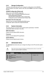
... [Disabled] [Compatible] [Enhanced] Enhanced Mode Support On [S-ATA] Sets Serial ATA, Parallel ATA or both as native mode. The BIOS automatically detects the items in this menu allow you to malfunction. Take caution when changing the settings of the general system specifications. System... menu. Select an item then press if you to set or change the settings for the CPU and other system devices. Chapter 2: BIOS information 2-6 Processor Displays the auto-detected CPU specification. Configuration options: [S-ATA] [S-ATA+P-ATA] [P-ATA]. ATA/IDE Configuration [Enhanced] ...
... [Disabled] [Compatible] [Enhanced] Enhanced Mode Support On [S-ATA] Sets Serial ATA, Parallel ATA or both as native mode. The BIOS automatically detects the items in this menu allow you to malfunction. Take caution when changing the settings of the general system specifications. System... menu. Select an item then press if you to set or change the settings for the CPU and other system devices. Chapter 2: BIOS information 2-6 Processor Displays the auto-detected CPU specification. Configuration options: [S-ATA] [S-ATA+P-ATA] [P-ATA]. ATA/IDE Configuration [Enhanced] ...

User Manual
Page 32
...show the CPU-related information that supports the Enhanced Intel SpeedStep® Technology (EIST). Configuration options: [Enabled] [Disabled] 2-7 ASUS P5G41T-M LX2 Series Virtualization enhanced by Intel® Virtualization Technology allows a platform to use the Enhanced Intel® SpeedStep® Technology. Configuration...Enabled] Execute-Disable Bit Capability [Enabled] Allows you installed an Intel® Pentium® 4 or later CPU that the BIOS automatically detects. Ratio CMOS Setting [Auto] Sets the ration between CPU core clock and the FSB frequency. C1E Support [...
...show the CPU-related information that supports the Enhanced Intel SpeedStep® Technology (EIST). Configuration options: [Enabled] [Disabled] 2-7 ASUS P5G41T-M LX2 Series Virtualization enhanced by Intel® Virtualization Technology allows a platform to use the Enhanced Intel® SpeedStep® Technology. Configuration...Enabled] Execute-Disable Bit Capability [Enabled] Allows you installed an Intel® Pentium® 4 or later CPU that the BIOS automatically detects. Ratio CMOS Setting [Auto] Sets the ration between CPU core clock and the FSB frequency. C1E Support [...
User Manual
Page 33
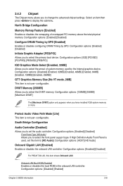
...] [Disabled] Front Panel Type [HD Audio] Allows you to change the advanced chipset settings. Configuration options: [Enabled] [Disabled] For P5G41T-M LX2, this item to select the primary boot device. Onboard LAN Boot ROM [Disabled] Enables or disables the boot ROM in the onboard LAN...display the submenu. Select an item then press to select the DVMT memory. Configuration options: [Disabled] [Enabled] Chapter 2: BIOS information 2-8 Configuration options: [Enabled] [Disabled] Configure DRAM Timing by SPD [Enabled] Enables or disables configuring DRAM Timing by the Internal graphics ...
...] [Disabled] Front Panel Type [HD Audio] Allows you to change the advanced chipset settings. Configuration options: [Enabled] [Disabled] For P5G41T-M LX2, this item to select the primary boot device. Onboard LAN Boot ROM [Disabled] Enables or disables the boot ROM in the onboard LAN...display the submenu. Select an item then press to select the DVMT memory. Configuration options: [Disabled] [Enabled] Chapter 2: BIOS information 2-8 Configuration options: [Enabled] [Disabled] Configure DRAM Timing by SPD [Enabled] Enables or disables configuring DRAM Timing by the Internal graphics ...

User Manual
Page 35
... options: [Disabled] [Enabled] [Auto] USB 2.0 Controller Mode [HiSpeed] Allows you to set the maximum time that the BIOS waits for Legacy USB storage devices, including USB flash drives and USB hard drives. If no USB device is detected, the legacy.... If detected, the USB controller legacy mode is plugged in. Configuration options: [Auto] [Floppy] [Forced FDD] [Hard Disk] [CDROM] Chapter 2: BIOS information 2-10 Configuration options: [Disabled] [Enabled] USB 2.0 Controller [Enabled] Enables or disables USB 2.0 controller. Configuration options: [FullSpeed] [HiSpeed] The...
... options: [Disabled] [Enabled] [Auto] USB 2.0 Controller Mode [HiSpeed] Allows you to set the maximum time that the BIOS waits for Legacy USB storage devices, including USB flash drives and USB hard drives. If no USB device is detected, the legacy.... If detected, the USB controller legacy mode is plugged in. Configuration options: [Auto] [Floppy] [Forced FDD] [Hard Disk] [CDROM] Chapter 2: BIOS information 2-10 Configuration options: [Disabled] [Enabled] USB 2.0 Controller [Enabled] Enables or disables USB 2.0 controller. Configuration options: [FullSpeed] [HiSpeed] The...
User Manual
Page 36
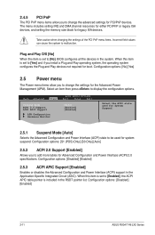
... and Play operating system, the operating system configures the Plug and Play devices not required for PCI/PnP devices. Main Advanced Power BIOS SETUP UTILITY Boot Tools Exit Suspend Mode [Auto] ACPI 2.0 Support [Enabled] ACPI APIC Support [Enabled] APM Configuration Hardware Monitor ...this item is set to [Enabled], the ACPI APIC table pointer is set to [No], BIOS configures all the devices in the RSDT pointer list. Configuration options: [Disabled] [Enabled] 2-11 ASUS P5G41T-M LX2 Series Select an item then press to malfunction. 2.4.5 PCI PnP The PCI PnP menu items...
... and Play operating system, the operating system configures the Plug and Play devices not required for PCI/PnP devices. Main Advanced Power BIOS SETUP UTILITY Boot Tools Exit Suspend Mode [Auto] ACPI 2.0 Support [Enabled] ACPI APIC Support [Enabled] APM Configuration Hardware Monitor ...this item is set to [Enabled], the ACPI APIC table pointer is set to [No], BIOS configures all the devices in the RSDT pointer list. Configuration options: [Disabled] [Enabled] 2-11 ASUS P5G41T-M LX2 Series Select an item then press to malfunction. 2.4.5 PCI PnP The PCI PnP menu items...

User Manual
Page 37
... [Enabled], the items RTC Alarm Date, RTC Alarm Hour, RTC Alarm Minute, and RTC Alarm Second appear with set values. Configuration options: [Disabled] [Enabled] Chapter 2: BIOS information 2-12 This feature requires an ATX power supply that provides at least 1A on the +5VSB lead. When this item is set to be...
... [Enabled], the items RTC Alarm Date, RTC Alarm Hour, RTC Alarm Minute, and RTC Alarm Second appear with set values. Configuration options: [Disabled] [Enabled] Chapter 2: BIOS information 2-12 This feature requires an ATX power supply that provides at least 1A on the +5VSB lead. When this item is set to be...


