User Manual
Page 1
Motherboard P5G41T-M LX V2 P5G41T-M LX PLUS
Motherboard P5G41T-M LX V2 P5G41T-M LX PLUS
User Manual
Page 10
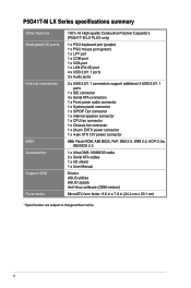
... summary Other features Back panel I/O ports Internal connectors BIOS Accessories Support DVD Form factor 100% All High-quality Conductive Polymer Capacitors (P5G41T-M LX PLUS only) 1 x PS/2 keyboard port (purple) 1 x PS/2 mouse port (green) 1 x LPT port 1 x COM port 1 x VGA port 1 x LAN (RJ-45) port 4 x USB...2.0, ACPI 2.0a, SM BIOS 2.5 1 x Ultra DMA 100/66/33 cable 2 x Serial ATA cables 1 x I/O shield 1 x User Manual Drivers ASUS utilities ASUS Update Anti-Virus software (OEM version) MicroATX form factor: 9.6 in x 7.9 in (24.4 cm x 20.1 cm) * Specifications are subject to change without notice....
... summary Other features Back panel I/O ports Internal connectors BIOS Accessories Support DVD Form factor 100% All High-quality Conductive Polymer Capacitors (P5G41T-M LX PLUS only) 1 x PS/2 keyboard port (purple) 1 x PS/2 mouse port (green) 1 x LPT port 1 x COM port 1 x VGA port 1 x LAN (RJ-45) port 4 x USB...2.0, ACPI 2.0a, SM BIOS 2.5 1 x Ultra DMA 100/66/33 cable 2 x Serial ATA cables 1 x I/O shield 1 x User Manual Drivers ASUS utilities ASUS Update Anti-Virus software (OEM version) MicroATX form factor: 9.6 in x 7.9 in (24.4 cm x 20.1 cm) * Specifications are subject to change without notice....
User Manual
Page 11
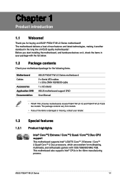
... processors, which are excellent for the following items. Motherboard Cables Accessories Application DVD Documentation ASUS P5G41T-M LX Series motherboard 2 x Serial ATA cables 1 x Ultra DMA 100/66/33 cable 1 x I/O shield ASUS motherboard support DVD User Manual • P5G41T-M LX Series motherboards include P5G41T-M LX V2 and P5G41T-M LX PLUS two models. Thank you start installing the motherboard, and hardware devices on it...
... processors, which are excellent for the following items. Motherboard Cables Accessories Application DVD Documentation ASUS P5G41T-M LX Series motherboard 2 x Serial ATA cables 1 x Ultra DMA 100/66/33 cable 1 x I/O shield ASUS motherboard support DVD User Manual • P5G41T-M LX Series motherboards include P5G41T-M LX V2 and P5G41T-M LX PLUS two models. Thank you start installing the motherboard, and hardware devices on it...
User Manual
Page 12
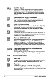
... supports hard drives based on the headphone while playing multichannel network games. 100% All High-quality Conductive Polymer Capacitors (P5G41T-M LX PLUS only) This motherboard uses all high-quality conductive polymer capacitors for 3D graphics and other memory-demanding applications. Gigabit LAN...The onboard LAN controller is a unique power saving technology that features data transfer rates of the memory accesses. Innovative ASUS features ASUS EPU ASUS EPU is a highly integrated Gb LAN controller. Dual channel DDR3 1333 (O.C.)/1066 support This motherboard supports DDR3 memory...
... supports hard drives based on the headphone while playing multichannel network games. 100% All High-quality Conductive Polymer Capacitors (P5G41T-M LX PLUS only) This motherboard uses all high-quality conductive polymer capacitors for 3D graphics and other memory-demanding applications. Gigabit LAN...The onboard LAN controller is a unique power saving technology that features data transfer rates of the memory accesses. Innovative ASUS features ASUS EPU ASUS EPU is a highly integrated Gb LAN controller. Dual channel DDR3 1333 (O.C.)/1066 support This motherboard supports DDR3 memory...
User Manual
Page 14
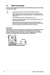
... note of the onboard LED. Failure to do so may cause severe damage to indicate that the ATX power supply is switched off mode. P5G41T-M LX PLUS Onboard LED P5G41T-M LX PLUS 1-4 Chapter 1: Product introduction The illustration below shows the location of the following precautions before you install motherboard components or change any motherboard settings. •...
... note of the onboard LED. Failure to do so may cause severe damage to indicate that the ATX power supply is switched off mode. P5G41T-M LX PLUS Onboard LED P5G41T-M LX PLUS 1-4 Chapter 1: Product introduction The illustration below shows the location of the following precautions before you install motherboard components or change any motherboard settings. •...
User Manual
Page 15
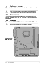
... your chassis to ensure that you unplug the power cord before installing or removing the motherboard. Place this side towards the rear of the chassis P5G41T-M LX PLUS ASUS P5G41T-M LX Series 1-5
... your chassis to ensure that you unplug the power cord before installing or removing the motherboard. Place this side towards the rear of the chassis P5G41T-M LX PLUS ASUS P5G41T-M LX Series 1-5
User Manual
Page 16
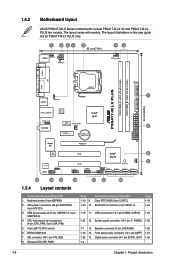
...connectors (7-pin SATA1-4) Page 1-18 1-24 1-19 11. The layout illustrations in this user guide are for P5G41T-M LX PLUS only. 20.1cm(7.9in) COM1 P5G41T-M LX PLUS RTL 8111E ICS 9LRS954A4 9 15 14 13 12 11 10 1.5.4 Layout contents Connectors/Jumpers/Slots/LED 1. ...USB78) 1-24 1-25 12. Digital audio connector (4-1 pin SPDIF_OUT) 1-25 1-4 1-6 Chapter 1: Product introduction 1.5.3 Motherboard layout ASUS P5G41T-M LX Series motherboards include P5G41T-M LX V2 and P5G41T-M LX PLUS two models. The layout varies with models. USB device wake-up (3-pin USBPW1-4, 3-pin USBPW5-8) 4.
...connectors (7-pin SATA1-4) Page 1-18 1-24 1-19 11. The layout illustrations in this user guide are for P5G41T-M LX PLUS only. 20.1cm(7.9in) COM1 P5G41T-M LX PLUS RTL 8111E ICS 9LRS954A4 9 15 14 13 12 11 10 1.5.4 Layout contents Connectors/Jumpers/Slots/LED 1. ...USB78) 1-24 1-25 12. Digital audio connector (4-1 pin SPDIF_OUT) 1-25 1-4 1-6 Chapter 1: Product introduction 1.5.3 Motherboard layout ASUS P5G41T-M LX Series motherboards include P5G41T-M LX V2 and P5G41T-M LX PLUS two models. The layout varies with models. USB device wake-up (3-pin USBPW1-4, 3-pin USBPW5-8) 4.
User Manual
Page 17
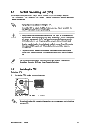
...8226; The product warranty does not cover damage to the PnP cap/socket contacts/motherboard components. ASUS P5G41T-M LX Series 1-7 Locate the CPU socket on the motherboard. P5G41T-M LX PLUS P5G41T-M LX PLUS CPU socket 775 Before installing the CPU, ensure that the PnP cap is on the socket ...and the socket contacts are not bent. ASUS will shoulder the cost of the PnP cap. 1.6 Central Processing ...
...8226; The product warranty does not cover damage to the PnP cap/socket contacts/motherboard components. ASUS P5G41T-M LX Series 1-7 Locate the CPU socket on the motherboard. P5G41T-M LX PLUS P5G41T-M LX PLUS CPU socket 775 Before installing the CPU, ensure that the PnP cap is on the socket ...and the socket contacts are not bent. ASUS will shoulder the cost of the PnP cap. 1.6 Central Processing ...
User Manual
Page 21
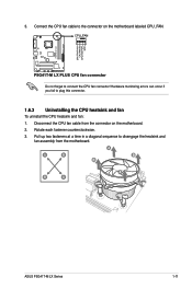
... CPU fan cable from the motherboard. Rotate each fastener counterclockwise. 3. Hardware monitoring errors can occur if you fail to connect the CPU fan connector! A A B B B A B A ASUS P5G41T-M LX Series 1-11 P5G41T-M LX PLUS P5G41T-M LX PLUS CPU fan connector Do not forget to plug this connector. 1.6.3 Uninstalling the CPU heatsink and fan To uninstall the CPU heatsink and fan: 1. Connect...
... CPU fan cable from the motherboard. Rotate each fastener counterclockwise. 3. Hardware monitoring errors can occur if you fail to connect the CPU fan connector! A A B B B A B A ASUS P5G41T-M LX Series 1-11 P5G41T-M LX PLUS P5G41T-M LX PLUS CPU fan connector Do not forget to plug this connector. 1.6.3 Uninstalling the CPU heatsink and fan To uninstall the CPU heatsink and fan: 1. Connect...
User Manual
Page 22
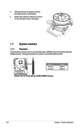
Carefully remove the heatsink and fan assembly from the motherboard. 5. The figure illustrates the location of the DDR3 DIMM sockets: P5G41T-M LX PLUS Channel Channel A Channel B P5G41T-M LX PLUS 240-pin DDR3 DIMM sockets Sockets DIMM_A1 DIMM_B1 1-12 Chapter 1: Product introduction 4. Rotate each fastener clockwise to ensure correct orientation when reinstalling. 1.7 System memory 1.7.1 Overview The motherboard comes with two Double Data Rate 3 (DDR3) Dual Inline Memory Modules (DIMM) sockets.
Carefully remove the heatsink and fan assembly from the motherboard. 5. The figure illustrates the location of the DDR3 DIMM sockets: P5G41T-M LX PLUS Channel Channel A Channel B P5G41T-M LX PLUS 240-pin DDR3 DIMM sockets Sockets DIMM_A1 DIMM_B1 1-12 Chapter 1: Product introduction 4. Rotate each fastener clockwise to ensure correct orientation when reinstalling. 1.7 System memory 1.7.1 Overview The motherboard comes with two Double Data Rate 3 (DDR3) Dual Inline Memory Modules (DIMM) sockets.

User Manual
Page 28
P5G41T-M LX PLUS Clear RTC RAM To erase the RTC RAM: 1. Plug the power cord and turn ON the computer. 4. You can clear the CMOS memory of date, ... automatically resets parameter settings to clear the CMOS RTC RAM data. Shut down the key during the boot process and enter BIOS setup to overclocking. P5G41T-M LX PLUS 1.9 Jumpers 1. Removing the cap will cause system boot failure! • If the steps above do not need to clear the RTC when the system hangs...
P5G41T-M LX PLUS Clear RTC RAM To erase the RTC RAM: 1. Plug the power cord and turn ON the computer. 4. You can clear the CMOS memory of date, ... automatically resets parameter settings to clear the CMOS RTC RAM data. Shut down the key during the boot process and enter BIOS setup to overclocking. P5G41T-M LX PLUS 1.9 Jumpers 1. Removing the cap will cause system boot failure! • If the steps above do not need to clear the RTC when the system hangs...
User Manual
Page 29
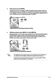
...device wake-up • The USB device wake-up from S1 sleep mode (CPU stopped, DRAM refreshed, system running in sleep mode. P5G41T-M LX PLUS ASUS P5G41T-M LX Series 1-19 When you set this jumper to pins 2-3 (+5VSB), you to enable or disable the keyboard wake-up the computer from .... otherwise, the system would not power up the computer by pressing a key on the +5VSB lead, and a corresponding setting in reduced power mode). P5G41T-M LX PLUS 2. USB device wake-up (3-pin USBPW1-4, 3-pin USBPW5-8) Set these jumpers to +5V to CPU, DRAM in slow refresh, power supply in the BIOS...
...device wake-up • The USB device wake-up from S1 sleep mode (CPU stopped, DRAM refreshed, system running in sleep mode. P5G41T-M LX PLUS ASUS P5G41T-M LX Series 1-19 When you set this jumper to pins 2-3 (+5VSB), you to enable or disable the keyboard wake-up the computer from .... otherwise, the system would not power up the computer by pressing a key on the +5VSB lead, and a corresponding setting in reduced power mode). P5G41T-M LX PLUS 2. USB device wake-up (3-pin USBPW1-4, 3-pin USBPW5-8) Set these jumpers to +5V to CPU, DRAM in slow refresh, power supply in the BIOS...
User Manual
Page 31
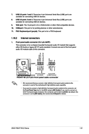
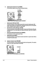
... module to this connector, set the Front Panel Type item in the BIOS setup to [HD Audio]. USB 2.0 ports 3 and 4. P5G41T-M LX PLUS Front panel audio connector • We recommend that supports either HD Audio or legacy AC`97 audio standard. By default, this connector. COM.... PS/2 Keyboard port (purple). This port is set the item to this connector is for a VGA monitor or other serial devices. 11. P5G41T-M LX PLUS ASUS P5G41T-M LX Series 1-21 VGA port. USB 2.0 ports 1 and 2. These two 4-pin Universal Serial Bus (USB) ports are available for details. Connect one...
... module to this connector, set the Front Panel Type item in the BIOS setup to [HD Audio]. USB 2.0 ports 3 and 4. P5G41T-M LX PLUS Front panel audio connector • We recommend that supports either HD Audio or legacy AC`97 audio standard. By default, this connector. COM.... PS/2 Keyboard port (purple). This port is set the item to this connector is for a VGA monitor or other serial devices. 11. P5G41T-M LX PLUS ASUS P5G41T-M LX Series 1-21 VGA port. USB 2.0 ports 1 and 2. These two 4-pin Universal Serial Bus (USB) ports are available for details. Connect one...

User Manual
Page 32
... three connectors on the IDE connector is set as "Cable-Select," ensure that all other device jumpers have the same setting. 1-22 Chapter 1: Product introduction P5G41T-M LX PLUS P5G41T-M LX PLUS IDE connector If any device jumper is removed to configure your device.
... three connectors on the IDE connector is set as "Cable-Select," ensure that all other device jumpers have the same setting. 1-22 Chapter 1: Product introduction P5G41T-M LX PLUS P5G41T-M LX PLUS IDE connector If any device jumper is removed to configure your device.
User Manual
Page 33
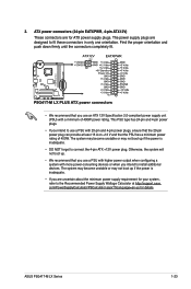
P5G41T-M LX PLUS 3. com/PowerSupplyCalculator/PSCalculator.aspx?SLanguage=en-us for ATX power supply plugs. This PSU type has 24-pin and 4-pin power plugs. • If you ... you intend to use a PSU with 20-pin and 4-pin power plugs, ensure that the 20-pin power plug can provide at http://support.asus. ASUS P5G41T-M LX Series 1-23 P5G41T-M LX PLUS ATX power connectors • We recommend that the PSU has a minimum power rating of 400W power rating. The system may become unstable or may...
P5G41T-M LX PLUS 3. com/PowerSupplyCalculator/PSCalculator.aspx?SLanguage=en-us for ATX power supply plugs. This PSU type has 24-pin and 4-pin power plugs. • If you ... you intend to use a PSU with 20-pin and 4-pin power plugs, ensure that the 20-pin power plug can provide at http://support.asus. ASUS P5G41T-M LX Series 1-23 P5G41T-M LX PLUS ATX power connectors • We recommend that the PSU has a minimum power rating of 400W power rating. The system may become unstable or may...
User Manual
Page 34
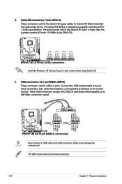
...standard parallel ATA with Serial ATA 1.5Gb/s specification. P5G41T-M LX PLUS P5G41T-M LX PLUS USB2.0 connectors Never connect a 1394 cable to 480 Mbps connection speed. The Serial ATA 3Gb/s is backward compatible with 133 MB/s (Ultra DMA133). P5G41T-M LX PLUS SATA connectors Install the Windows® XP Service Pack...later version before using Serial ATA. 5. These USB connectors comply with USB 2.0 specification that supports up to the USB connectors. P5G41T-M LX PLUS 4. Connect the USB module cable to any of these connectors, then install the module to a slot opening at the back...
...standard parallel ATA with Serial ATA 1.5Gb/s specification. P5G41T-M LX PLUS P5G41T-M LX PLUS USB2.0 connectors Never connect a 1394 cable to 480 Mbps connection speed. The Serial ATA 3Gb/s is backward compatible with 133 MB/s (Ultra DMA133). P5G41T-M LX PLUS SATA connectors Install the Windows® XP Service Pack...later version before using Serial ATA. 5. These USB connectors comply with USB 2.0 specification that supports up to the USB connectors. P5G41T-M LX PLUS 4. Connect the USB module cable to any of these connectors, then install the module to a slot opening at the back...
User Manual
Page 35
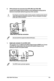
... cable to this connector, then install the module to a slot opening at the back of the connector. P5G41T-M LX PLUS P5G41T-M LX PLUS Onboard LED The S/PDIF module is for an additional Sony/Philips Digital Interface (S/PDIF) port. 6. ASUS P5G41T-M LX Series 1-25 Insufficient air flow inside the system may damage the motherboard components. CPU and chassis fan connectors...
... cable to this connector, then install the module to a slot opening at the back of the connector. P5G41T-M LX PLUS P5G41T-M LX PLUS Onboard LED The S/PDIF module is for an additional Sony/Philips Digital Interface (S/PDIF) port. 6. ASUS P5G41T-M LX Series 1-25 Insufficient air flow inside the system may damage the motherboard components. CPU and chassis fan connectors...
User Manual
Page 36
...disk drive activity LED (2-pin +HDLED) This 2-pin connector is for the chassis-mounted reset button for the system power LED. P5G41T-M LX PLUS P5G41T-M LX PLUS Speaker out connector 1-26 Chapter 1: Product introduction Connect the HDD Activity LED cable to the HDD. • ATX power button/... warning speaker. Speaker connector (4-pin SPEAKER) This 4-pin connector is for system reboot without turning off the system power. 9. P5G41T-M LX PLUS P5G41T-M LX PLUS System panel connector • System power LED (2-pin PLED) This 2-pin connector is for the HDD Activity LED. Connect the...
...disk drive activity LED (2-pin +HDLED) This 2-pin connector is for the chassis-mounted reset button for the system power LED. P5G41T-M LX PLUS P5G41T-M LX PLUS Speaker out connector 1-26 Chapter 1: Product introduction Connect the HDD Activity LED cable to the HDD. • ATX power button/... warning speaker. Speaker connector (4-pin SPEAKER) This 4-pin connector is for system reboot without turning off the system power. 9. P5G41T-M LX PLUS P5G41T-M LX PLUS System panel connector • System power LED (2-pin PLED) This 2-pin connector is for the HDD Activity LED. Connect the...
User Manual
Page 40
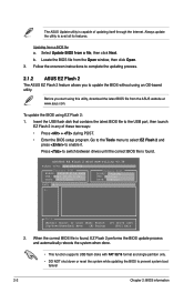
...BIOS from the Open window, then click Open. 3. ASUSTek EZ Flash 2 BIOS ROM Utility V3.36 FLASH TYPE: EON 25P/F80 Current ROM BOARD: P5G41T-M LX PLUS VER: 0301 (H:00 B:00) DATE: 09/17/2010 Update ROM BOARD: Unknown VER: Unknown DATE: Unknown PATH: A:\ A: Note [Enter] Select or Load... the utility to update the BIOS without using an OS‑based utility. Follow the onscreen instructions to complete the updating process. 2.1.2 ASUS EZ Flash 2 The ASUS EZ Flash 2 feature allows you start using EZ Flash 2: 1. b. To update the BIOS using this utility, download the latest BIOS...
...BIOS from the Open window, then click Open. 3. ASUSTek EZ Flash 2 BIOS ROM Utility V3.36 FLASH TYPE: EON 25P/F80 Current ROM BOARD: P5G41T-M LX PLUS VER: 0301 (H:00 B:00) DATE: 09/17/2010 Update ROM BOARD: Unknown VER: Unknown DATE: Unknown PATH: A:\ A: Note [Enter] Select or Load... the utility to update the BIOS without using an OS‑based utility. Follow the onscreen instructions to complete the updating process. 2.1.2 ASUS EZ Flash 2 The ASUS EZ Flash 2 feature allows you start using EZ Flash 2: 1. b. To update the BIOS using this utility, download the latest BIOS...
User Manual
Page 62
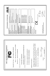
.... 150, LI-TE RD., PEITOU, TAIPEI 112, TAIWAN R.O.C. Country: TAIWAN Authorized representative in Europe: ASUS COMPUTER GmbH Address, City: HARKORT STR. 21-23, 40880 RATINGEN Country: GERMANY declare the following apparatus: Product name : Motherboard Model name : P5G41T-M LX PLUS, P5G41T-M LX V2 conform with part 15 of Conformity We, the undersigned, Manufacturer: Address, City: ASUSTek COMPUTER...
.... 150, LI-TE RD., PEITOU, TAIPEI 112, TAIWAN R.O.C. Country: TAIWAN Authorized representative in Europe: ASUS COMPUTER GmbH Address, City: HARKORT STR. 21-23, 40880 RATINGEN Country: GERMANY declare the following apparatus: Product name : Motherboard Model name : P5G41T-M LX PLUS, P5G41T-M LX V2 conform with part 15 of Conformity We, the undersigned, Manufacturer: Address, City: ASUSTek COMPUTER...

