
User Manual
Page 1
P5G41T-M LE Motherboard
P5G41T-M LE Motherboard
User Manual
Page 3
Contents Notices...vi Safety information vii About this guide vii P5G41T-M LE specifications summary ix Chapter 1: Product introduction 1.1 Welcome 1-1 1.2 Package contents 1-1 1.3 Special features 1-1 1.3.1 Product highlights 1-1 1.3.2 Innovative ASUS features 1-2 1.4 Before you proceed 1-4 1.5 Motherboard overview 1-5 1.5.1 Placement direction 1-5 1.5.2 Screw holes 1-5 1.5.3 Motherboard layout 1-6 1.5.4 Layout contents 1-6 1.6 Central Processing Unit (CPU 1-7 1.6.1 Installing the CPU 1-7 1.6.2 Installing the CPU heatsink and fan 1-10 1.6.3 Uninstalling...
Contents Notices...vi Safety information vii About this guide vii P5G41T-M LE specifications summary ix Chapter 1: Product introduction 1.1 Welcome 1-1 1.2 Package contents 1-1 1.3 Special features 1-1 1.3.1 Product highlights 1-1 1.3.2 Innovative ASUS features 1-2 1.4 Before you proceed 1-4 1.5 Motherboard overview 1-5 1.5.1 Placement direction 1-5 1.5.2 Screw holes 1-5 1.5.3 Motherboard layout 1-6 1.5.4 Layout contents 1-6 1.6 Central Processing Unit (CPU 1-7 1.6.1 Installing the CPU 1-7 1.6.2 Installing the CPU heatsink and fan 1-10 1.6.3 Uninstalling...
User Manual
Page 6
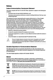
.../TV technician for compliance could void the user's authority to radio communications. This class B digital apparatus complies with FCC regulations. vi DO NOT throw the motherboard in our products at ASUS REACH website at http://green.asus.com/english/REACH.htm. Changes or modifications to assure compliance with Canadian ICES-003.
.../TV technician for compliance could void the user's authority to radio communications. This class B digital apparatus complies with FCC regulations. vi DO NOT throw the motherboard in our products at ASUS REACH website at http://green.asus.com/english/REACH.htm. Changes or modifications to assure compliance with Canadian ICES-003.
User Manual
Page 7
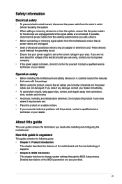
... ensure that all cables are correctly connected and the power cables are not damaged. If you are not sure about the voltage of the motherboard and the new technology it supports. • Chapter 2: BIOS information This chapter tells how to fix it by yourself. If you are ...power cables are using an adapter or extension cord. Operation safety • Before installing the motherboard and adding devices on a stable surface. • If you need when installing and configuring the motherboard. These devices could interrupt the grounding circuit. • Ensure that the power cables for ...
... ensure that all cables are correctly connected and the power cables are not damaged. If you are not sure about the voltage of the motherboard and the new technology it supports. • Chapter 2: BIOS information This chapter tells how to fix it by yourself. If you are ...power cables are using an adapter or extension cord. Operation safety • Before installing the motherboard and adding devices on a stable surface. • If you need when installing and configuring the motherboard. These devices could interrupt the grounding circuit. • Ensure that the power cables for ...
User Manual
Page 11
...; 2 Quad/ Core™ 2 Duo processors, which are excellent for multitasking, multimedia, and enthusiastic gamers with the list below. 1.2 Package contents Check your motherboard package for buying an ASUS® P5G41T-M LE motherboard! ASUS P5G41T-M LE 1-1 The motherboard delivers a host of new features and latest technologies, making it , check the items in your package with 1333/1066/800 MHz FSB.
...; 2 Quad/ Core™ 2 Duo processors, which are excellent for multitasking, multimedia, and enthusiastic gamers with the list below. 1.2 Package contents Check your motherboard package for buying an ASUS® P5G41T-M LE motherboard! ASUS P5G41T-M LE 1-1 The motherboard delivers a host of new features and latest technologies, making it , check the items in your package with 1333/1066/800 MHz FSB.
User Manual
Page 12
...time. Serial ATA 3Gb/s technology This motherboard supports hard drives based on the Serial ATA (SATA) 3Gb/s storage specifications, delivering enhanced scalability and doubling the bus bandwidth for advanced operating systems. Innovative ASUS features ASUS EPU ASUS EPU (Energy Processing Unit) provides total...and temperature, enabling users to work or games, simply through pressing the button. ASUS Anti-Surge Protection This special design prevents expensive devices and the motherboard from damage caused by detecting the current PC loading and intelligently moderating power in distraction...
...time. Serial ATA 3Gb/s technology This motherboard supports hard drives based on the Serial ATA (SATA) 3Gb/s storage specifications, delivering enhanced scalability and doubling the bus bandwidth for advanced operating systems. Innovative ASUS features ASUS EPU ASUS EPU (Energy Processing Unit) provides total...and temperature, enabling users to work or games, simply through pressing the button. ASUS Anti-Surge Protection This special design prevents expensive devices and the motherboard from damage caused by detecting the current PC loading and intelligently moderating power in distraction...
User Manual
Page 13
... BIOS file. It supports file downloading to overclocking failure. C.P.R. (CPU Parameter Recall) The BIOS C.P.R. Green ASUS This motherboard and its packaging comply with the ASUS vision of Hazardous Substances (RoHS). feature automatically restores the CPU default settings when the system hangs due to USB...without using the bundled support DVD or USB flash disk that allows you to their default settings. ASUS P5G41T-M LE 1-3 When installing it on the environment. ASUS EZ Flash 2 ASUS EZ Flash 2 is in line with the European Union's Restriction on the use of creating ...
... BIOS file. It supports file downloading to overclocking failure. C.P.R. (CPU Parameter Recall) The BIOS C.P.R. Green ASUS This motherboard and its packaging comply with the ASUS vision of Hazardous Substances (RoHS). feature automatically restores the CPU default settings when the system hangs due to USB...without using the bundled support DVD or USB flash disk that allows you to their default settings. ASUS P5G41T-M LE 1-3 When installing it on the environment. ASUS EZ Flash 2 ASUS EZ Flash 2 is in line with the European Union's Restriction on the use of creating ...
User Manual
Page 14
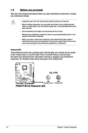
The illustration below shows the location of the following precautions before you install motherboard components or change any motherboard settings. • Unplug the power cord from the power supply. This is a reminder that you install or remove any component, ensure that ...to static electricity. • Hold components by the edges to avoid touching the ICs on them. • Whenever you uninstall any motherboard component. Onboard LED The motherboard comes with the component. • Before you must shut down the system and unplug the power cable before removing or plugging in soft...
The illustration below shows the location of the following precautions before you install motherboard components or change any motherboard settings. • Unplug the power cord from the power supply. This is a reminder that you install or remove any component, ensure that ...to static electricity. • Hold components by the edges to avoid touching the ICs on them. • Whenever you uninstall any motherboard component. Onboard LED The motherboard comes with the component. • Before you must shut down the system and unplug the power cable before removing or plugging in soft...
User Manual
Page 15
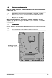
... correct orientation. Do not overtighten the screws! Place this side towards the rear of the chassis ASUS P5G41T-M LE 1-5 Doing so can cause you unplug the power cord before installing or removing the motherboard. 1.5 Motherboard overview Before you install the motherboard, study the configuration of your chassis to ensure that you place it . Failure to the...
... correct orientation. Do not overtighten the screws! Place this side towards the rear of the chassis ASUS P5G41T-M LE 1-5 Doing so can cause you unplug the power cord before installing or removing the motherboard. 1.5 Motherboard overview Before you install the motherboard, study the configuration of your chassis to ensure that you place it . Failure to the...
User Manual
Page 17
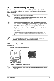
... from incorrect CPU installation/removal, or misplacement/loss/incorrect removal of the PnP cap. ASUS P5G41T-M LE 1-7 ASUS will shoulder the cost of repair only if the damage is shipment/transit-related. • Keep the cap after installing the motherboard. The motherboard supports Intel® LGA775 processors with the Intel® Enhanced Intel SpeedStep® Technology...
... from incorrect CPU installation/removal, or misplacement/loss/incorrect removal of the PnP cap. ASUS P5G41T-M LE 1-7 ASUS will shoulder the cost of repair only if the damage is shipment/transit-related. • Keep the cap after installing the motherboard. The motherboard supports Intel® LGA775 processors with the Intel® Enhanced Intel SpeedStep® Technology...
User Manual
Page 20
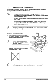
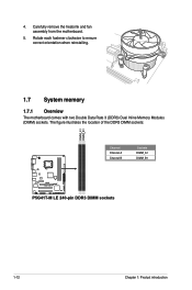
...and requires no tool to install. • If you purchased a separate CPU heatsink and fan assembly, ensure that you have installed the motherboard to the chassis before you install the heatsink and fan assembly. To install the CPU heatsink and fan: 1. Orient the heatsink and fan... assembly such that the four fasteners match the holes on the motherboard. A B A B B A 1 1 B A The type of the installed CPU, ensuring that the CPU fan cable is for reference only. 1-10 Chapter 1: Product ...
...and requires no tool to install. • If you purchased a separate CPU heatsink and fan assembly, ensure that you have installed the motherboard to the chassis before you install the heatsink and fan assembly. To install the CPU heatsink and fan: 1. Orient the heatsink and fan... assembly such that the four fasteners match the holes on the motherboard. A B A B B A 1 1 B A The type of the installed CPU, ensuring that the CPU fan cable is for reference only. 1-10 Chapter 1: Product ...
User Manual
Page 21
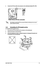
Do not forget to plug this connector. 1.6.3 Uninstalling the CPU heatsink and fan To uninstall the CPU heatsink and fan: 1. Connect the CPU fan cable to disengage the heatsink and fan assembly from the connector on the motherboard labeled CPU_FAN. Pull up two fasteners at a time in a diagonal sequence to the connector on the motherboard. 2. A A B B B A B A ASUS P5G41T-M LE 1-11 Rotate each fastener counterclockwise. 3. 3. Disconnect the CPU fan cable from the motherboard. Hardware monitoring errors can occur if you fail to connect the CPU fan connector!
Do not forget to plug this connector. 1.6.3 Uninstalling the CPU heatsink and fan To uninstall the CPU heatsink and fan: 1. Connect the CPU fan cable to disengage the heatsink and fan assembly from the connector on the motherboard labeled CPU_FAN. Pull up two fasteners at a time in a diagonal sequence to the connector on the motherboard. 2. A A B B B A B A ASUS P5G41T-M LE 1-11 Rotate each fastener counterclockwise. 3. 3. Disconnect the CPU fan cable from the motherboard. Hardware monitoring errors can occur if you fail to connect the CPU fan connector!
User Manual
Page 22
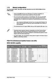
4. Rotate each fastener clockwise to ensure correct orientation when reinstalling. 1.7 System memory 1.7.1 Overview The motherboard comes with two Double Data Rate 3 (DDR3) Dual Inline Memory Modules (DIMM) sockets. Carefully remove the heatsink and fan assembly from the motherboard. 5. The figure illustrates the location of the DDR3 DIMM sockets: Channel Channel A Channel B Sockets DIMM_A1 DIMM_B1 1-12 Chapter 1: Product introduction
4. Rotate each fastener clockwise to ensure correct orientation when reinstalling. 1.7 System memory 1.7.1 Overview The motherboard comes with two Double Data Rate 3 (DDR3) Dual Inline Memory Modules (DIMM) sockets. Carefully remove the heatsink and fan assembly from the motherboard. 5. The figure illustrates the location of the DDR3 DIMM sockets: Channel Channel A Channel B Sockets DIMM_A1 DIMM_B1 1-12 Chapter 1: Product introduction
User Manual
Page 23
...; • Micron 9HF22D9KPT 7- • • Samsung SEC 901 HCF8 K4B1G0846E - - • • SAMSUNG 846 K4B2G0846B-HCF8 -- • • ASUS P5G41T-M LE 1-13 P5G41T-M LE Motherboard Qualified Vendors Lists (QVL) DDR3-1066 MHz capability Vendor Part No. Under the default state, some memory modules for the OS can be about 3GB...Chip NO. Install a 64-bit Windows® OS when you want to install 4GB or more memory on the motherboard. • This motherboard does not support DIMMs made up of 256 megabits (Mb) chips or less. • The default memory operation ...
...; • Micron 9HF22D9KPT 7- • • Samsung SEC 901 HCF8 K4B1G0846E - - • • SAMSUNG 846 K4B2G0846B-HCF8 -- • • ASUS P5G41T-M LE 1-13 P5G41T-M LE Motherboard Qualified Vendors Lists (QVL) DDR3-1066 MHz capability Vendor Part No. Under the default state, some memory modules for the OS can be about 3GB...Chip NO. Install a 64-bit Windows® OS when you want to install 4GB or more memory on the motherboard. • This motherboard does not support DIMMs made up of 256 megabits (Mb) chips or less. • The default memory operation ...
User Manual
Page 25
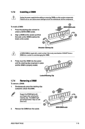
... removing DIMMs or other system components. Simultaneously press the retaining clips outward to both the motherboard and the components. Locked Retaining Clip 1.7.4 Removing a DIMM To remove a DIMM: 1. Remove the DIMM from the socket. 2 1 DDR3 DIMM notch ASUS P5G41T-M LE 1-15 To install a DIMM: 1. Firmly insert the DIMM into a socket to unlock a DDR3 DIMM socket...
... removing DIMMs or other system components. Simultaneously press the retaining clips outward to both the motherboard and the components. Locked Retaining Clip 1.7.4 Removing a DIMM To remove a DIMM: 1. Remove the DIMM from the socket. 2 1 DDR3 DIMM notch ASUS P5G41T-M LE 1-15 To install a DIMM: 1. Firmly insert the DIMM into a socket to unlock a DDR3 DIMM socket...
User Manual
Page 26
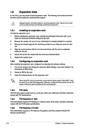
... card connector with it by adjusting the software settings. 1. When using PCI cards on the slot. 5. Remove the system unit cover (if your motherboard is completely seated on shared slots, ensure that the drivers support "Share IRQ" or that the cards do so may need IRQ assignments. Secure the... cards such as a LAN card, SCSI card, USB card, and other cards that comply with PCI specifications. 1.8.4 PCI Express x1 slot This motherboard supports PCI Express x1 network cards, SCSI cards, and other cards that comply with the PCI Express specifications. 1.8.5 PCI Express x16 slot This...
... card connector with it by adjusting the software settings. 1. When using PCI cards on the slot. 5. Remove the system unit cover (if your motherboard is completely seated on shared slots, ensure that the drivers support "Share IRQ" or that the cards do so may need IRQ assignments. Secure the... cards such as a LAN card, SCSI card, USB card, and other cards that comply with PCI specifications. 1.8.4 PCI Express x1 slot This motherboard supports PCI Express x1 network cards, SCSI cards, and other cards that comply with the PCI Express specifications. 1.8.5 PCI Express x16 slot This...
User Manual
Page 29
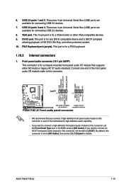
USB 2.0 ports 3 and 4. This 15-pin port is for a VGA monitor or other protected content. 10. PS/2 Keyboard port (purple). ASUS P5G41T-M LE 1-19 USB 2.0 ports 1 and 2. Front panel audio connector (10-1 pin AAFP) This connector is for a chassis-mounted front panel audio I /O module ...DVD, Blu-Ray, and other VGA-compatible devices. 9. This port is for any DVI-D compatible device and is HDCP compliant allowing playback of the motherboard's high-definition audio capability. • If you want to connect a high-definition front panel audio module to this connector is for a PS/2 ...
USB 2.0 ports 3 and 4. This 15-pin port is for a VGA monitor or other protected content. 10. PS/2 Keyboard port (purple). ASUS P5G41T-M LE 1-19 USB 2.0 ports 1 and 2. Front panel audio connector (10-1 pin AAFP) This connector is for a chassis-mounted front panel audio I /O module ...DVD, Blu-Ray, and other VGA-compatible devices. 9. This port is for any DVI-D compatible device and is HDCP compliant allowing playback of the motherboard's high-definition audio capability. • If you want to connect a high-definition front panel audio module to this connector is for a PS/2 ...
User Manual
Page 30
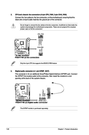
... connect the fan cables to a slot opening at the back of the connector. Only the 4-pin CPU fan supports the ASUS Q-FAN feature. 3. Do not place jumper caps on the motherboard, ensuring that the black wire of each cable matches the ground pin of the system chassis. CPU and chassis fan connectors...
... connect the fan cables to a slot opening at the back of the connector. Only the 4-pin CPU fan supports the ASUS Q-FAN feature. 3. Do not place jumper caps on the motherboard, ensuring that the black wire of each cable matches the ground pin of the system chassis. CPU and chassis fan connectors...
User Manual
Page 33
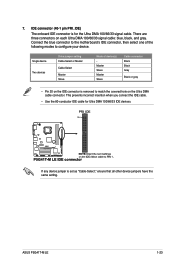
ASUS P5G41T-M LE 1-23 If any device jumper is for Ultra DMA 100/66/33 IDE devices. Connect the blue connector to the motherboard's IDE connector, then select one of device(s) Master Slave Master Slave Cable connector Black Black Gray Black or gray • Pin 20 on the IDE ...
ASUS P5G41T-M LE 1-23 If any device jumper is for Ultra DMA 100/66/33 IDE devices. Connect the blue connector to the motherboard's IDE connector, then select one of device(s) Master Slave Master Slave Cable connector Black Black Gray Black or gray • Pin 20 on the IDE ...

User Manual
Page 35
9. USB connectors (10-1 pin USB56, USB78) These connectors are for USB 2.0 ports. Never connect a 1394 cable to 480 Mbps connection speed. ASUS P5G41T-M LE 1-25 These USB connectors comply with USB 2.0 specification that supports up to the USB connectors. The USB module cable is standardized as a printer. LPT connector (... cable to any of these connectors, then install the module to a slot opening at the back of the system chassis. Doing so will damage the motherboard! LPT is purchased separately. 10.
9. USB connectors (10-1 pin USB56, USB78) These connectors are for USB 2.0 ports. Never connect a 1394 cable to 480 Mbps connection speed. ASUS P5G41T-M LE 1-25 These USB connectors comply with USB 2.0 specification that supports up to the USB connectors. The USB module cable is standardized as a printer. LPT connector (... cable to any of these connectors, then install the module to a slot opening at the back of the system chassis. Doing so will damage the motherboard! LPT is purchased separately. 10.


