

User Manual
Page 1
P5G41T-M Motherboard
P5G41T-M Motherboard

User Manual
Page 3
Contents Notices...vi Safety information vii About this guide vii P5G41T-M specifications summary ix Chapter 1: Product introduction 1.1 Welcome 1-1 1.2 Package contents 1-1 1.3 Special features 1-1 1.3.1 Product highlights 1-1 1.3.2 Innovative ASUS features 1-2 1.4 Before you proceed 1-4 1.5 Motherboard overview 1-5 1.5.1 Placement direction 1-5 1.5.2 Screw holes 1-5 1.5.3 Motherboard layout 1-6 1.5.4 Layout contents 1-6 1.6 Central Processing Unit (CPU 1-7 1.6.1 Installing the CPU 1-7 1.6.2 Installing the CPU heatsink and fan 1-10 1.6.3 Uninstalling...
Contents Notices...vi Safety information vii About this guide vii P5G41T-M specifications summary ix Chapter 1: Product introduction 1.1 Welcome 1-1 1.2 Package contents 1-1 1.3 Special features 1-1 1.3.1 Product highlights 1-1 1.3.2 Innovative ASUS features 1-2 1.4 Before you proceed 1-4 1.5 Motherboard overview 1-5 1.5.1 Placement direction 1-5 1.5.2 Screw holes 1-5 1.5.3 Motherboard layout 1-6 1.5.4 Layout contents 1-6 1.6 Central Processing Unit (CPU 1-7 1.6.1 Installing the CPU 1-7 1.6.2 Installing the CPU heatsink and fan 1-10 1.6.3 Uninstalling...

User Manual
Page 6
...proper reuse of the FCC Rules. This class B digital apparatus complies with Part 15 of parts and recycling. DO NOT throw the motherboard in the Radio Interference Regulations of the Canadian Department of the crossed out wheeled bin indicates that may cause undesired operation. Check local regulations... published the chemical substances in municipal waste. DO NOT throw the mercury-containing button cell battery in our products at ASUS REACH website at http://green.asus.com/english/REACH.htm. This equipment has been tested and found to comply with the limits for connection of the ...
...proper reuse of the FCC Rules. This class B digital apparatus complies with Part 15 of parts and recycling. DO NOT throw the motherboard in the Radio Interference Regulations of the Canadian Department of the crossed out wheeled bin indicates that may cause undesired operation. Check local regulations... published the chemical substances in municipal waste. DO NOT throw the mercury-containing button cell battery in our products at ASUS REACH website at http://green.asus.com/english/REACH.htm. This equipment has been tested and found to comply with the limits for connection of the ...

User Manual
Page 7
...hazard, disconnect the power cable from the electric outlet before relocating the system. • When adding or removing devices to or from the motherboard, ensure that all power cables are unplugged. • Seek professional assistance before the signal cables are connected. If possible, disconnect all ... before you are using the product, ensure that the power cables for the devices are not sure about the voltage of the motherboard and the new technology it by yourself. How this guide This user guide contains the information you encounter technical problems with the package...
...hazard, disconnect the power cable from the electric outlet before relocating the system. • When adding or removing devices to or from the motherboard, ensure that all power cables are unplugged. • Seek professional assistance before the signal cables are connected. If possible, disconnect all ... before you are using the product, ensure that the power cables for the devices are not sure about the voltage of the motherboard and the new technology it by yourself. How this guide This user guide contains the information you encounter technical problems with the package...

User Manual
Page 11
... in the 45nm manufacturing process. Before you for the following items. Motherboard Cables Accessories Application DVD Documentation ASUS P5G41T-M motherboard 2 x Serial ATA cables 1 x Ultra DMA 100/66/33 cable 1 x I/O shield ASUS motherboard support DVD User Manual If any of ASUS quality motherboards! Thank you start installing the motherboard, and hardware devices on it another standout in the long line...
... in the 45nm manufacturing process. Before you for the following items. Motherboard Cables Accessories Application DVD Documentation ASUS P5G41T-M motherboard 2 x Serial ATA cables 1 x Ultra DMA 100/66/33 cable 1 x I/O shield ASUS motherboard support DVD User Manual If any of ASUS quality motherboards! Thank you start installing the motherboard, and hardware devices on it another standout in the long line...

User Manual
Page 12
... money. Serial ATA 3Gb/s technology This motherboard supports hard drives based on the Serial ATA (SATA) 3Gb/s storage specifications, delivering enhanced scalability and doubling the bus bandwidth for advanced operating systems. Innovative ASUS features ASUS EPU ASUS EPU (Energy Processing Unit) provides total...architecture, 1333/1066/800 Front Side Bus (FSB), PCIe 1.1, and mutli-core CPUs. ASUS Anti-Surge Protection This special design prevents expensive devices and the motherboard from damage caused by detecting the current PC loading and intelligently moderating power in distraction-free ...
... money. Serial ATA 3Gb/s technology This motherboard supports hard drives based on the Serial ATA (SATA) 3Gb/s storage specifications, delivering enhanced scalability and doubling the bus bandwidth for advanced operating systems. Innovative ASUS features ASUS EPU ASUS EPU (Energy Processing Unit) provides total...architecture, 1333/1066/800 Front Side Bus (FSB), PCIe 1.1, and mutli-core CPUs. ASUS Anti-Surge Protection This special design prevents expensive devices and the motherboard from damage caused by detecting the current PC loading and intelligently moderating power in distraction-free ...

User Manual
Page 13
... clear the RTC data. Green ASUS This motherboard and its packaging comply with at 1 meter accuracy. When installing it on USB HDDs or flash drives, connect the drives to convert your screen. ASUS P5G41T-M 1-3 ASUS Express Gate Express Gate is an ASUS exclusive OS, which lets you... using an OS-based utility. C.P.R. eliminates the need to their default settings. ASUS MyLogo2™ This feature allows you to the motherboard USB port before entering the Windows® OS. • ASUS Express Gate supports installation on your favorite photo into a 256-color boot logo ...
... clear the RTC data. Green ASUS This motherboard and its packaging comply with at 1 meter accuracy. When installing it on USB HDDs or flash drives, connect the drives to convert your screen. ASUS P5G41T-M 1-3 ASUS Express Gate Express Gate is an ASUS exclusive OS, which lets you... using an OS-based utility. C.P.R. eliminates the need to their default settings. ASUS MyLogo2™ This feature allows you to the motherboard USB port before entering the Windows® OS. • ASUS Express Gate supports installation on your favorite photo into a 256-color boot logo ...

User Manual
Page 14
.... 1-4 Chapter 1: Product introduction The illustration below shows the location of the following precautions before you install motherboard components or change any motherboard settings. • Unplug the power cord from the power supply. Onboard LED The motherboard comes with the component. • Before you must shut down the system and unplug the power cable...
.... 1-4 Chapter 1: Product introduction The illustration below shows the location of the following precautions before you install motherboard components or change any motherboard settings. • Unplug the power cord from the power supply. Onboard LED The motherboard comes with the component. • Before you must shut down the system and unplug the power cable...

User Manual
Page 15
Doing so can cause you physical injury and damage motherboard components. 1.5.1 Placement direction When installing the motherboard, ensure that you place it . Failure to do so can damage the motherboard. Place this side towards the rear of the chassis ASUS P5G41T-M 1-5 The edge with external ports goes to the rear part of the chassis as indicated...
Doing so can cause you physical injury and damage motherboard components. 1.5.1 Placement direction When installing the motherboard, ensure that you place it . Failure to do so can damage the motherboard. Place this side towards the rear of the chassis ASUS P5G41T-M 1-5 The edge with external ports goes to the rear part of the chassis as indicated...

User Manual
Page 17
... To install a CPU: 1. ASUS will shoulder the cost of the PnP cap. Locate the CPU socket on your retailer immediately if the PnP cap is shipment/transit-related. • Keep the cap after installing the motherboard. ASUS will process Return Merchandise Authorization (...RMA) requests only if the motherboard comes with the cap on the LGA775 socket. • The product warranty does not cover damage to the PnP cap/socket contacts/motherboard components. ASUS P5G41T-M 1-7 Contact your left...
... To install a CPU: 1. ASUS will shoulder the cost of the PnP cap. Locate the CPU socket on your retailer immediately if the PnP cap is shipment/transit-related. • Keep the cap after installing the motherboard. ASUS will process Return Merchandise Authorization (...RMA) requests only if the motherboard comes with the cap on the LGA775 socket. • The product warranty does not cover damage to the PnP cap/socket contacts/motherboard components. ASUS P5G41T-M 1-7 Contact your left...

User Manual
Page 20
...fan assembly comes in place. Ensure that the CPU fan cable is for reference only. 1-10 Chapter 1: Product introduction Place the heatsink on the motherboard. Orient the heatsink and fan assembly such that you have properly applied Thermal Interface Material to the CPU fan connector. 2. To install the CPU heatsink... sequence to secure the heatsink and fan assembly in a push-pin design and requires no tool to install. • If you have installed the motherboard to ensure optimum thermal condition and performance. • When you install the heatsink and fan assembly.
...fan assembly comes in place. Ensure that the CPU fan cable is for reference only. 1-10 Chapter 1: Product introduction Place the heatsink on the motherboard. Orient the heatsink and fan assembly such that you have properly applied Thermal Interface Material to the CPU fan connector. 2. To install the CPU heatsink... sequence to secure the heatsink and fan assembly in a push-pin design and requires no tool to install. • If you have installed the motherboard to ensure optimum thermal condition and performance. • When you install the heatsink and fan assembly.

User Manual
Page 21
Disconnect the CPU fan cable from the motherboard. Hardware monitoring errors can occur if you fail to connect the CPU fan connector! 3. Rotate each fastener counterclockwise. 3. Do not forget to plug this connector. 1.6.3 Uninstalling the CPU heatsink and fan To uninstall the CPU heatsink and fan: 1. Pull up two fasteners at a time in a diagonal sequence to the connector on the motherboard. 2. A A B B B A B A ASUS P5G41T-M 1-11 Connect the CPU fan cable to disengage the heatsink and fan assembly from the connector on the motherboard labeled CPU_FAN.
Disconnect the CPU fan cable from the motherboard. Hardware monitoring errors can occur if you fail to connect the CPU fan connector! 3. Rotate each fastener counterclockwise. 3. Do not forget to plug this connector. 1.6.3 Uninstalling the CPU heatsink and fan To uninstall the CPU heatsink and fan: 1. Pull up two fasteners at a time in a diagonal sequence to the connector on the motherboard. 2. A A B B B A B A ASUS P5G41T-M 1-11 Connect the CPU fan cable to disengage the heatsink and fan assembly from the connector on the motherboard labeled CPU_FAN.

User Manual
Page 22
Rotate each fastener clockwise to ensure correct orientation when reinstalling. 1.7 System memory 1.7.1 Overview The motherboard comes with two Double Data Rate 3 (DDR3) Dual Inline Memory Modules (DIMM) sockets. Carefully remove the heatsink and fan assembly from the motherboard. 5. 4. The figure illustrates the location of the DDR3 DIMM sockets: Channel Channel A Channel B Sockets DIMM_A1 DIMM_B1 1-12 Chapter 1: Product introduction
Rotate each fastener clockwise to ensure correct orientation when reinstalling. 1.7 System memory 1.7.1 Overview The motherboard comes with two Double Data Rate 3 (DDR3) Dual Inline Memory Modules (DIMM) sockets. Carefully remove the heatsink and fan assembly from the motherboard. 5. 4. The figure illustrates the location of the DDR3 DIMM sockets: Channel Channel A Channel B Sockets DIMM_A1 DIMM_B1 1-12 Chapter 1: Product introduction
User Manual
Page 23
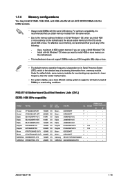
...value. • For system stability, use a more efficient cooling system to install 4GB or more memory on the motherboard. • This motherboard does not support DIMMs made up of 256 megabits (Mb) chips or less. • The default memory operation frequency...; • Micron 9HF22D9KPT 7- • • Samsung SEC 901 HCF8 K4B1G0846E - - • • SAMSUNG 846 K4B2G0846B-HCF8 -- • • ASUS P5G41T-M 1-13 For optimum compatibility, it is recommended that you obtain memory modules from a memory module. Under the default state, some memory modules for the OS...
...value. • For system stability, use a more efficient cooling system to install 4GB or more memory on the motherboard. • This motherboard does not support DIMMs made up of 256 megabits (Mb) chips or less. • The default memory operation frequency...; • Micron 9HF22D9KPT 7- • • Samsung SEC 901 HCF8 K4B1G0846E - - • • SAMSUNG 846 K4B2G0846B-HCF8 -- • • ASUS P5G41T-M 1-13 For optimum compatibility, it is recommended that you obtain memory modules from a memory module. Under the default state, some memory modules for the OS...

User Manual
Page 25
... motherboard and the components. Support the DIMM lightly with extra force. 1 2. The DIMM might get damaged when it fits in place 3 and the DIMM is properly seated. 1.7.3 Installing a DIMM Unplug the power supply before adding or removing DIMMs or other system components. Remove the DIMM from the socket. 2 1 DDR3 DIMM notch ASUS P5G41T...
... motherboard and the components. Support the DIMM lightly with extra force. 1 2. The DIMM might get damaged when it fits in place 3 and the DIMM is properly seated. 1.7.3 Installing a DIMM Unplug the power supply before adding or removing DIMMs or other system components. Remove the DIMM from the socket. 2 1 DDR3 DIMM notch ASUS P5G41T...

User Manual
Page 26
...installing the expansion card, read the documentation that the cards do so may need IRQ assignments. Remove the system unit cover (if your motherboard is completely seated on BIOS setup. 2. Align the card connector with it by adjusting the software settings. 1. The following sub‑... expansion card. Failure to do not need to use . 4. 1.8 Expansion slots In the future, you may cause you physical injury and damage motherboard components. 1.8.1 Installing an expansion card To install an expansion card: 1. Secure the card to the card. 3. Install the software drivers for the...
...installing the expansion card, read the documentation that the cards do so may need IRQ assignments. Remove the system unit cover (if your motherboard is completely seated on BIOS setup. 2. Align the card connector with it by adjusting the software settings. 1. The following sub‑... expansion card. Failure to do not need to use . 4. 1.8 Expansion slots In the future, you may cause you physical injury and damage motherboard components. 1.8.1 Installing an expansion card To install an expansion card: 1. Secure the card to the card. 3. Install the software drivers for the...

User Manual
Page 29
.... 11. 6. These two 4-pin Universal Serial Bus (USB) ports are available for details. This port is HDCP compliant allowing playback of the motherboard's high-definition audio capability. • If you want to connect an AC'97 front panel audio module to this connector, set the item to...definition front panel audio module to this connector, set to an external audio output device via an optical S/PDIF cable. 7. USB 2.0 ports 3 and 4. ASUS P5G41T-M 1-19 This port is set the Front Panel Type item in the BIOS setup to avail of HD DVD, Blu-ray, and other VGA-compatible...
.... 11. 6. These two 4-pin Universal Serial Bus (USB) ports are available for details. This port is HDCP compliant allowing playback of the motherboard's high-definition audio capability. • If you want to connect an AC'97 front panel audio module to this connector, set the item to...definition front panel audio module to this connector, set to an external audio output device via an optical S/PDIF cable. 7. USB 2.0 ports 3 and 4. ASUS P5G41T-M 1-19 This port is set the Front Panel Type item in the BIOS setup to avail of HD DVD, Blu-ray, and other VGA-compatible...

User Manual
Page 30
... forget to connect the fan cables to a slot opening at the back of the connector. Do not place jumper caps on the motherboard, ensuring that the black wire of each cable matches the ground pin of the system chassis. The S/PDIF module is for an ...additional Sony/Philips Digital Interface (S/PDIF) port. Only the 4-pin CPU fan supports the ASUS Q-FAN feature. 3. Digital audio connector (4-1 pin SPDIF_OUT) This connector is purchased separately. 1-20 Chapter 1: Product introduction These are not jumpers! 2. ...
... forget to connect the fan cables to a slot opening at the back of the connector. Do not place jumper caps on the motherboard, ensuring that the black wire of each cable matches the ground pin of the system chassis. The S/PDIF module is for an ...additional Sony/Philips Digital Interface (S/PDIF) port. Only the 4-pin CPU fan supports the ASUS Q-FAN feature. 3. Digital audio connector (4-1 pin SPDIF_OUT) This connector is purchased separately. 1-20 Chapter 1: Product introduction These are not jumpers! 2. ...

User Manual
Page 33
IDE connector (40-1 pin PRI_IDE) The onboard IDE connector is for Ultra DMA 100/66/33 IDE devices. Connect the blue connector to the motherboard's IDE connector, then select one of device(s) Master Slave Master Slave Cable connector Black Black Gray Black or gray • Pin 20 on the IDE ... Master Slave Mode of the following modes to match the covered hole on each Ultra DMA 100/66/33 signal cable: blue, black, and gray. ASUS P5G41T-M 1-23 If any device jumper is removed to configure your device. 7. There are three connectors on the Ultra DMA cable connector.
IDE connector (40-1 pin PRI_IDE) The onboard IDE connector is for Ultra DMA 100/66/33 IDE devices. Connect the blue connector to the motherboard's IDE connector, then select one of device(s) Master Slave Master Slave Cable connector Black Black Gray Black or gray • Pin 20 on the IDE ... Master Slave Mode of the following modes to match the covered hole on each Ultra DMA 100/66/33 signal cable: blue, black, and gray. ASUS P5G41T-M 1-23 If any device jumper is removed to configure your device. 7. There are three connectors on the Ultra DMA cable connector.

User Manual
Page 35
... these connectors, then install the module to a slot opening at the back of the system chassis. Never connect a 1394 cable to 480 Mbps connection speed. ASUS P5G41T-M 1-25 The serial port module is purchased separately. Doing so will damage the motherboard! 9.
... these connectors, then install the module to a slot opening at the back of the system chassis. Never connect a 1394 cable to 480 Mbps connection speed. ASUS P5G41T-M 1-25 The serial port module is purchased separately. Doing so will damage the motherboard! 9.


