
User Manual
Page 1
P5G41C-M Motherboard
P5G41C-M Motherboard
User Manual
Page 3
Contents Notices...vi Safety information vii About this guide vii P5G41C-M specifications summary ix Chapter 1: Product introduction 1.1 Welcome 1-1 1.2 Package contents 1-1 1.3 Special features 1-1 1.3.1 Product highlights 1-1 1.3.2 Innovative ASUS features 1-2 1.4 Before you proceed 1-4 1.5 Motherboard overview 1-5 1.5.1 Placement direction 1-5 1.5.2 Screw holes 1-5 1.5.3 Motherboard layout 1-6 1.5.4 Layout contents 1-6 1.6 Central Processing Unit (CPU 1-7 1.6.1 Installing the CPU 1-7 1.6.2 Installing the CPU heatsink and fan 1-10 1.6.3 Uninstalling...
Contents Notices...vi Safety information vii About this guide vii P5G41C-M specifications summary ix Chapter 1: Product introduction 1.1 Welcome 1-1 1.2 Package contents 1-1 1.3 Special features 1-1 1.3.1 Product highlights 1-1 1.3.2 Innovative ASUS features 1-2 1.4 Before you proceed 1-4 1.5 Motherboard overview 1-5 1.5.1 Placement direction 1-5 1.5.2 Screw holes 1-5 1.5.3 Motherboard layout 1-6 1.5.4 Layout contents 1-6 1.6 Central Processing Unit (CPU 1-7 1.6.1 Installing the CPU 1-7 1.6.2 Installing the CPU heatsink and fan 1-10 1.6.3 Uninstalling...
User Manual
Page 6
...wheeled bin indicates that interference will not occur in accordance with manufacturer's instructions, may cause undesired operation. DO NOT throw the motherboard in a residential installation. This symbol of Chemicals) regulatory framework, we published the chemical substances in municipal waste. Notices Federal ...complies with Part 15 of Communications. This equipment generates, uses and can be placed in our products at ASUS REACH website at http://green.asus.com/english/REACH.htm. These limits are designed to an outlet on a circuit different from digital apparatus ...
...wheeled bin indicates that interference will not occur in accordance with manufacturer's instructions, may cause undesired operation. DO NOT throw the motherboard in a residential installation. This symbol of Chemicals) regulatory framework, we published the chemical substances in municipal waste. Notices Federal ...complies with Part 15 of Communications. This equipment generates, uses and can be placed in our products at ASUS REACH website at http://green.asus.com/english/REACH.htm. These limits are designed to an outlet on a circuit different from digital apparatus ...
User Manual
Page 7
...How this guide This user guide contains the information you detect any area where it by yourself. Operation safety • Before installing the motherboard and adding devices on a stable surface. • If you add a device. • Before connecting or removing signal cables from...ensure that came with the product, contact a qualified service technician or your retailer. About this guide is set to or from the motherboard, ensure that all power cables are connected. vii Contact a qualified service technician or your retailer. These devices could interrupt the grounding ...
...How this guide This user guide contains the information you detect any area where it by yourself. Operation safety • Before installing the motherboard and adding devices on a stable surface. • If you add a device. • Before connecting or removing signal cables from...ensure that came with the product, contact a qualified service technician or your retailer. About this guide is set to or from the motherboard, ensure that all power cables are connected. vii Contact a qualified service technician or your retailer. These devices could interrupt the grounding ...
User Manual
Page 11
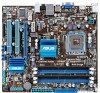
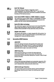
... your package with the list below. 1.2 Package contents Check your motherboard package for the following items. Motherboard Cables Accessories Application DVD Documentation ASUS P5G41C-M motherboard 2 x Serial ATA cables 1 x Ultra DMA 100/66/33 cable 1 x I/O shield ASUS motherboard support DVD User Manual If any of ASUS quality motherboards! This motherboard also supports Intel® CPUs in the long line of the...
... your package with the list below. 1.2 Package contents Check your motherboard package for the following items. Motherboard Cables Accessories Application DVD Documentation ASUS P5G41C-M motherboard 2 x Serial ATA cables 1 x Ultra DMA 100/66/33 cable 1 x I/O shield ASUS motherboard support DVD User Manual If any of ASUS quality motherboards! This motherboard also supports Intel® CPUs in the long line of the...
User Manual
Page 12
... Chipset is designed to save power and money. Gigabit LAN solution The onboard LAN controller is enhanced with minimal noise. ASUS Anti-Surge Protection This special design prevents expensive devices and the motherboard from switching power supply (PSU). 1-2 Chapter 1: Product introduction It is a highly integrated Gb LAN controller. After you to turn...
... Chipset is designed to save power and money. Gigabit LAN solution The onboard LAN controller is enhanced with minimal noise. ASUS Anti-Surge Protection This special design prevents expensive devices and the motherboard from switching power supply (PSU). 1-2 Chapter 1: Product introduction It is a highly integrated Gb LAN controller. After you to turn...
User Manual
Page 13
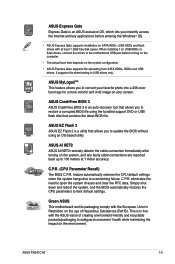
...motherboard USB port before entering the Windows® OS. • ASUS Express Gate supports installation on SATA HDDs, USB HDDs and flash drives with the ASUS vision of Hazardous Substances (RoHS). C.P.R. (CPU Parameter Recall) The BIOS C.P.R. This is in line with at 1 meter accuracy. ASUS P5G41C-M 1-3 C.P.R. ASUS... Express Gate Express Gate is an ASUS exclusive OS, which lets you instantly access the Internet and key applications before turning on the ...
...motherboard USB port before entering the Windows® OS. • ASUS Express Gate supports installation on SATA HDDs, USB HDDs and flash drives with the ASUS vision of Hazardous Substances (RoHS). C.P.R. (CPU Parameter Recall) The BIOS C.P.R. This is in line with at 1 meter accuracy. ASUS P5G41C-M 1-3 C.P.R. ASUS... Express Gate Express Gate is an ASUS exclusive OS, which lets you instantly access the Internet and key applications before turning on the ...
User Manual
Page 14
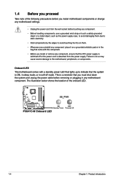
... avoid touching the ICs on them. • Whenever you uninstall any component, place it on a grounded antistatic pad or in any motherboard component. Onboard LED The motherboard comes with a standby power LED that the ATX power supply is a reminder that you must shut down the system and unplug the ... in the bag that came with the component. • Before you install or remove any component, ensure that lights up to the motherboard, peripherals, or components. This is switched off mode. 1.4 Before you proceed Take note of the onboard LED. 1-4 Chapter 1: Product introduction
... avoid touching the ICs on them. • Whenever you uninstall any component, place it on a grounded antistatic pad or in any motherboard component. Onboard LED The motherboard comes with a standby power LED that the ATX power supply is a reminder that you must shut down the system and unplug the ... in the bag that came with the component. • Before you install or remove any component, ensure that lights up to the motherboard, peripherals, or components. This is switched off mode. 1.4 Before you proceed Take note of the onboard LED. 1-4 Chapter 1: Product introduction
User Manual
Page 15
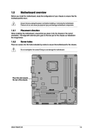
... you unplug the power cord before installing or removing the motherboard. Failure to do so can damage the motherboard. Place this side towards the rear of the chassis ASUS P5G41C-M 1-5 1.5 Motherboard overview Before you install the motherboard, study the configuration of your chassis to ensure that the motherboard fits into the holes indicated by circles to secure...
... you unplug the power cord before installing or removing the motherboard. Failure to do so can damage the motherboard. Place this side towards the rear of the chassis ASUS P5G41C-M 1-5 1.5 Motherboard overview Before you install the motherboard, study the configuration of your chassis to ensure that the motherboard fits into the holes indicated by circles to secure...
User Manual
Page 16
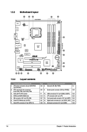
... 14. CPU and chassis fan connectors (4-pin CPU_FAN, 3-pin CHA_FAN) 3. DDR2 and DDR3 DIMM slots 5. Serial port connector (10-1 pin COM1) 1-29 1-6 Chapter 1: Product introduction 1.5.3 Motherboard layout 1.5.4 Layout contents Connectors/Jumpers/Slots/LED 1.
... 14. CPU and chassis fan connectors (4-pin CPU_FAN, 3-pin CHA_FAN) 3. DDR2 and DDR3 DIMM slots 5. Serial port connector (10-1 pin COM1) 1-29 1-6 Chapter 1: Product introduction 1.5.3 Motherboard layout 1.5.4 Layout contents Connectors/Jumpers/Slots/LED 1.
User Manual
Page 17
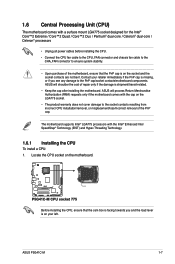
... is shipment/transit-related. • Keep the cap after installing the motherboard. ASUS P5G41C-M 1-7 Locate the CPU socket on the LGA775 socket. • The product warranty does not cover damage to the PnP cap/socket contacts/motherboard components. 1.6 Central Processing Unit (CPU) The motherboard comes with a surface mount LGA775 socket designed for the Intel®...
... is shipment/transit-related. • Keep the cap after installing the motherboard. ASUS P5G41C-M 1-7 Locate the CPU socket on the LGA775 socket. • The product warranty does not cover damage to the PnP cap/socket contacts/motherboard components. 1.6 Central Processing Unit (CPU) The motherboard comes with a surface mount LGA775 socket designed for the Intel®...
User Manual
Page 20
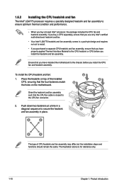
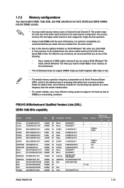
Place the heatsink on the motherboard. Ensure that you have properly applied Thermal Interface Material to the CPU fan connector. 2. To install the CPU heatsink and fan: 1. The illustration above is ... a push-pin design and requires no tool to install. • If you purchased a separate CPU heatsink and fan assembly, ensure that you have installed the motherboard to the chassis before you install the CPU fan and heatsink assembly. Push down two fasteners at a time in a diagonal sequence to ensure optimum thermal...
Place the heatsink on the motherboard. Ensure that you have properly applied Thermal Interface Material to the CPU fan connector. 2. To install the CPU heatsink and fan: 1. The illustration above is ... a push-pin design and requires no tool to install. • If you purchased a separate CPU heatsink and fan assembly, ensure that you have installed the motherboard to the chassis before you install the CPU fan and heatsink assembly. Push down two fasteners at a time in a diagonal sequence to ensure optimum thermal...
User Manual
Page 21
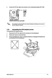
Do not forget to plug this connector. 1.6.3 Uninstalling the CPU heatsink and fan To uninstall the CPU heatsink and fan: 1. Rotate each fastener counterclockwise. 3. Disconnect the CPU fan cable from the motherboard. Hardware monitoring errors can occur if you fail to connect the CPU fan connector! A A B B B A B A ASUS P5G41C-M 1-11 Connect the CPU fan cable to disengage the heatsink and fan assembly from the connector on the motherboard labeled CPU_FAN. 3. Pull up two fasteners at a time in a diagonal sequence to the connector on the motherboard. 2.
Do not forget to plug this connector. 1.6.3 Uninstalling the CPU heatsink and fan To uninstall the CPU heatsink and fan: 1. Rotate each fastener counterclockwise. 3. Disconnect the CPU fan cable from the motherboard. Hardware monitoring errors can occur if you fail to connect the CPU fan connector! A A B B B A B A ASUS P5G41C-M 1-11 Connect the CPU fan cable to disengage the heatsink and fan assembly from the connector on the motherboard labeled CPU_FAN. 3. Pull up two fasteners at a time in a diagonal sequence to the connector on the motherboard. 2.

User Manual
Page 22
Carefully remove the heatsink and fan assembly from the motherboard. 5. The figure illustrates the location of the DIMM sockets: Channel Channel A Channel B Sockets DDR3_A1 and DDR2_A1 DDR3_B1 and DDR2_B1 1-12 Chapter 1: Product introduction Rotate each fastener clockwise to ensure correct orientation when reinstalling. 1.7 System memory 1.7.1 Overview The motherboard comes with two Double Data Rate 2 (DDR2) and two Double Data Rate 3 (DDR3) Dual Inline Memory Modules (DIMM) sockets. 4.
Carefully remove the heatsink and fan assembly from the motherboard. 5. The figure illustrates the location of the DIMM sockets: Channel Channel A Channel B Sockets DDR3_A1 and DDR2_A1 DDR3_B1 and DDR2_B1 1-12 Chapter 1: Product introduction Rotate each fastener clockwise to ensure correct orientation when reinstalling. 1.7 System memory 1.7.1 Overview The motherboard comes with two Double Data Rate 2 (DDR2) and two Double Data Rate 3 (DDR3) Dual Inline Memory Modules (DIMM) sockets. 4.
User Manual
Page 23
...; Elixir M2Y2G64CBHC9N-BE 2048MB DS Elixir - - - • • Kingtiger 2GB DIMM PC3-8500 2048MB DS Hynix H5TQ1G83AFP G7C - - • • ASUS P5G41C-M 1-13 The system maps the total size of the lower-sized channel for the OS can be about 3GB or less. For optimum compatibility, it...Under the default state, some memory modules for single-channel operation. • Always install DIMMs with the same CAS latency. P5G41C-M Motherboard Qualified Vendors Lists (QVL) DDR3-1066 MHz capability Vendor Part No. Any excess memory from the higher-sized channel is recommended ...
...; Elixir M2Y2G64CBHC9N-BE 2048MB DS Elixir - - - • • Kingtiger 2GB DIMM PC3-8500 2048MB DS Hynix H5TQ1G83AFP G7C - - • • ASUS P5G41C-M 1-13 The system maps the total size of the lower-sized channel for the OS can be about 3GB or less. For optimum compatibility, it...Under the default state, some memory modules for single-channel operation. • Always install DIMMs with the same CAS latency. P5G41C-M Motherboard Qualified Vendors Lists (QVL) DDR3-1066 MHz capability Vendor Part No. Any excess memory from the higher-sized channel is recommended ...
User Manual
Page 29
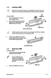
... in the wrong direction to unlock a DIMM socket. 2. Remove the DIMM from the socket. Simultaneously press the retaining clips outward to both the motherboard and the components. DIMM notch ASUS P5G41C-M 1-19 Align a DIMM on the socket such that the notch on the DIMM matches the DIMM slot key on the socket. 1 Unlocked...
... in the wrong direction to unlock a DIMM socket. 2. Remove the DIMM from the socket. Simultaneously press the retaining clips outward to both the motherboard and the components. DIMM notch ASUS P5G41C-M 1-19 Align a DIMM on the socket such that the notch on the DIMM matches the DIMM slot key on the socket. 1 Unlocked...
User Manual
Page 30
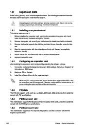
...the future, you may cause you intend to install expansion cards. Remove the bracket opposite the slot that you physical injury and damage motherboard components. 1.8.1 Installing an expansion card To install an expansion card: 1. Replace the system cover. 1.8.2 Configuring an expansion card After installing the...with the slot and press firmly until the card is already installed in a chassis). 3. Remove the system unit cover (if your motherboard is completely seated on the system and change the necessary BIOS settings, if any. Otherwise, conflicts will arise between the two PCI ...
...the future, you may cause you intend to install expansion cards. Remove the bracket opposite the slot that you physical injury and damage motherboard components. 1.8.1 Installing an expansion card To install an expansion card: 1. Replace the system cover. 1.8.2 Configuring an expansion card After installing the...with the slot and press firmly until the card is already installed in a chassis). 3. Remove the system unit cover (if your motherboard is completely seated on the system and change the necessary BIOS settings, if any. Otherwise, conflicts will arise between the two PCI ...
User Manual
Page 33
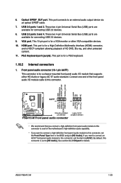
... connector, and is for connecting USB 2.0 devices. 9. HDMI port. PS/2 Keyboard port (purple). This port is HDCP compliant allowing playback of the motherboard's high-definition audio capability. • If you want to connect a high-definition front panel audio module to this connector, set to [HD Audio].... module that you connect a high-definition front panel audio module to avail of HD DVD, Blu-ray, and other VGA-compatible devices. 10. ASUS P5G41C-M 1-23 6. This 15-pin port is set the Front Panel Type item in the BIOS setup to this connector. • We recommend that ...
... connector, and is for connecting USB 2.0 devices. 9. HDMI port. PS/2 Keyboard port (purple). This port is HDCP compliant allowing playback of the motherboard's high-definition audio capability. • If you want to connect a high-definition front panel audio module to this connector, set to [HD Audio].... module that you connect a high-definition front panel audio module to avail of HD DVD, Blu-ray, and other VGA-compatible devices. 10. ASUS P5G41C-M 1-23 6. This 15-pin port is set the Front Panel Type item in the BIOS setup to this connector. • We recommend that ...
User Manual
Page 34
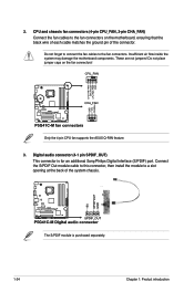
Insufficient air flow inside the system may damage the motherboard components. Digital audio connector (4-1 pin SPDIF_OUT) This connector is purchased separately. 1-24 Chapter 1: Product introduction Connect the S/PDIF Out module cable to this connector, then ... of the connector. These are not jumpers! Only the 4-pin CPU fan supports the ASUS Q-FAN feature. 3. The S/PDIF module is for an additional Sony/Philips Digital Interface (S/PDIF) port. Do not place jumper caps on the motherboard, ensuring that the black wire of each cable matches the ground pin of the...
Insufficient air flow inside the system may damage the motherboard components. Digital audio connector (4-1 pin SPDIF_OUT) This connector is purchased separately. 1-24 Chapter 1: Product introduction Connect the S/PDIF Out module cable to this connector, then ... of the connector. These are not jumpers! Only the 4-pin CPU fan supports the ASUS Q-FAN feature. 3. The S/PDIF module is for an additional Sony/Philips Digital Interface (S/PDIF) port. Do not place jumper caps on the motherboard, ensuring that the black wire of each cable matches the ground pin of the...
User Manual
Page 37
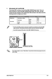
There are three connectors on the Ultra DMA cable connector. Connect the blue connector to the motherboard's IDE connector, then select one of device(s) Master Slave Master Slave Cable connector Black Black Gray Black or gray • Pin 20 on the IDE ... Master Slave Mode of the following modes to match the covered hole on each Ultra DMA 100/66/33 signal cable: blue, black, and gray. ASUS P5G41C-M 1-27 7.
There are three connectors on the Ultra DMA cable connector. Connect the blue connector to the motherboard's IDE connector, then select one of device(s) Master Slave Master Slave Cable connector Black Black Gray Black or gray • Pin 20 on the IDE ... Master Slave Mode of the following modes to match the covered hole on each Ultra DMA 100/66/33 signal cable: blue, black, and gray. ASUS P5G41C-M 1-27 7.


