
User Manual
Page 1
P5G41-M LE Motherboard
P5G41-M LE Motherboard
User Manual
Page 3
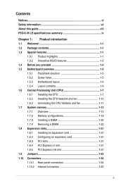
Contents Notices...vi Safety information vii About this guide viii P5G41-M LE specifications summary ix Chapter 1: Product introduction 1.1 Welcome 1-1 1.2 Package contents 1-1 1.3 Special features 1-1 1.3.1 Product highlights 1-1 1.3.2 Innovative ASUS features 1-2 1.4 Before you proceed 1-4 1.5 Motherboard overview 1-5 1.5.1 Placement direction 1-5 1.5.2 Screw holes 1-5 1.5.3 Motherboard layout 1-6 1.5.4 Layout contents 1-6 1.6 Central Processing Unit (CPU 1-7 1.6.1 Installing the CPU 1-7 1.6.2 Installing the CPU heatsink and fan 1-10 1.6.3 Uninstalling...
Contents Notices...vi Safety information vii About this guide viii P5G41-M LE specifications summary ix Chapter 1: Product introduction 1.1 Welcome 1-1 1.2 Package contents 1-1 1.3 Special features 1-1 1.3.1 Product highlights 1-1 1.3.2 Innovative ASUS features 1-2 1.4 Before you proceed 1-4 1.5 Motherboard overview 1-5 1.5.1 Placement direction 1-5 1.5.2 Screw holes 1-5 1.5.3 Motherboard layout 1-6 1.5.4 Layout contents 1-6 1.6 Central Processing Unit (CPU 1-7 1.6.1 Installing the CPU 1-7 1.6.2 Installing the CPU heatsink and fan 1-10 1.6.3 Uninstalling...
User Manual
Page 6
... reception, which the receiver is encouraged to try to which can radiate radio frequency energy and, if not installed and used in a residential installation. Notices ASUS REACH Complying with the REACH (Registration, Evaluation, Authorisation, and Restriction of the FCC Rules. This symbol of the FCC Rules. Federal Communications Commission Statement This...
... reception, which the receiver is encouraged to try to which can radiate radio frequency energy and, if not installed and used in a residential installation. Notices ASUS REACH Complying with the REACH (Registration, Evaluation, Authorisation, and Restriction of the FCC Rules. This symbol of the FCC Rules. Federal Communications Commission Statement This...
User Manual
Page 7
...release harmful substances into the environment. • Never dispose of the battery with the package. • Before using , contact your motherboard) and is broken, do not try to the correct voltage in environments with an incorrect battery type. • RISK OF EXPLOSION ...INSTRUCTIONS. It could interrupt the grounding circuit. • Make sure that came with your area. Operation safety • Before installing the motherboard and adding devices on it by yourself. vii Contact a qualified service technician or your dealer immediately. • To avoid short circuits,...
...release harmful substances into the environment. • Never dispose of the battery with the package. • Before using , contact your motherboard) and is broken, do not try to the correct voltage in environments with an incorrect battery type. • RISK OF EXPLOSION ...INSTRUCTIONS. It could interrupt the grounding circuit. • Make sure that came with your area. Operation safety • Before installing the motherboard and adding devices on it by yourself. vii Contact a qualified service technician or your dealer immediately. • To avoid short circuits,...
User Manual
Page 8
... information on ASUS hardware and software products. Conventions used throughout this manual. These documents are also provided. Keys enclosed in this guide To make sure that you perform certain tasks properly, take note of the BIOS parameters are not part of the motherboard and the ... it supports. • Chapter 2: BIOS information This chapter tells how to help you need when installing and configuring the motherboard. NOTE: Tips and additional information to change system settings through the BIOS Setup menus. Optional documentation Your product package may have...
... information on ASUS hardware and software products. Conventions used throughout this manual. These documents are also provided. Keys enclosed in this guide To make sure that you perform certain tasks properly, take note of the BIOS parameters are not part of the motherboard and the ... it supports. • Chapter 2: BIOS information This chapter tells how to help you need when installing and configuring the motherboard. NOTE: Tips and additional information to change system settings through the BIOS Setup menus. Optional documentation Your product package may have...
User Manual
Page 11
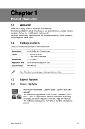
... devices on it another standout in the 45nm manufacturing process. This motherboard also supports Intel® CPUs in the long line of ASUS quality motherboards! The motherboard delivers a host of the above items is damaged or missing, contact... contents Check your motherboard package for buying an ASUS® P5G41-M LE motherboard! ASUS P5G41-M LE 1-1 Before you for the following items. Motherboard Cables Accessories Application DVD Documentation ASUS P5G41-M LE motherboard 2 x Serial ATA cables 1 x Ultra DMA 100/66 cable 1 x I/O shield ASUS motherboard support DVD User ...
... devices on it another standout in the 45nm manufacturing process. This motherboard also supports Intel® CPUs in the long line of ASUS quality motherboards! The motherboard delivers a host of the above items is damaged or missing, contact... contents Check your motherboard package for buying an ASUS® P5G41-M LE motherboard! ASUS P5G41-M LE 1-1 Before you for the following items. Motherboard Cables Accessories Application DVD Documentation ASUS P5G41-M LE motherboard 2 x Serial ATA cables 1 x Ultra DMA 100/66 cable 1 x I/O shield ASUS motherboard support DVD User ...
User Manual
Page 12
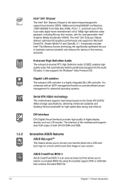
... and support for high-speed data saving and retrieval. Innovative ASUS features ASUS MyLogo2™ This feature allows you to provide efficient power management for advanced operating systems. Serial ATA 3Gb/s technology This motherboard supports hard drives based on your favorite photo into the audio...® Graphics Media Acceleratior X4500. It provides digital home entertainment of both DVI-D/HDMI and RGB. The interface of this motherboard supports dual VGA output of full 1080p high-definition video playback, including Blu-ray disc movies, with an ACPI management function...
... and support for high-speed data saving and retrieval. Innovative ASUS features ASUS MyLogo2™ This feature allows you to provide efficient power management for advanced operating systems. Serial ATA 3Gb/s technology This motherboard supports hard drives based on your favorite photo into the audio...® Graphics Media Acceleratior X4500. It provides digital home entertainment of both DVI-D/HDMI and RGB. The interface of this motherboard supports dual VGA output of full 1080p high-definition video playback, including Blu-ray disc movies, with an ACPI management function...
User Manual
Page 13
... Protection This special design protects expensive devices and the motherboard from damage caused by power surges from switching power supply (PSU). Turbo Key ASUS Turbo Key allows you to 100 meters at 1 meter accuracy. C.P.R. (CPU Parameter Recall) The BIOS C.P.R. C.P.R. This is ... BIOS automatically restores the CPU parameters to open the system chassis and clear the RTC data. ASUS P5G41-M LE 1-3 ASUS EZ Flash 2 ASUS EZ Flash 2 is in real-time. ASUS Q-Fan ASUS Q-Fan technology intelligently adjusts CPU fan speeds according to system loading to update the BIOS without ...
... Protection This special design protects expensive devices and the motherboard from damage caused by power surges from switching power supply (PSU). Turbo Key ASUS Turbo Key allows you to 100 meters at 1 meter accuracy. C.P.R. (CPU Parameter Recall) The BIOS C.P.R. C.P.R. This is ... BIOS automatically restores the CPU parameters to open the system chassis and clear the RTC data. ASUS P5G41-M LE 1-3 ASUS EZ Flash 2 ASUS EZ Flash 2 is in real-time. ASUS Q-Fan ASUS Q-Fan technology intelligently adjusts CPU fan speeds according to system loading to update the BIOS without ...

User Manual
Page 14
... system and unplug the power cable before you proceed Take note of the onboard LED. SB_PWR P5G41-M LE ON OFF Standy Power Powered Off P5G41-M LE Onboard LED 1-4 Chapter 1: Product introduction 1.4 Before you install motherboard components or change any motherboard settings. • Unplug the power cord from the power supply. The illustration below shows the location...
... system and unplug the power cable before you proceed Take note of the onboard LED. SB_PWR P5G41-M LE ON OFF Standy Power Powered Off P5G41-M LE Onboard LED 1-4 Chapter 1: Product introduction 1.4 Before you install motherboard components or change any motherboard settings. • Unplug the power cord from the power supply. The illustration below shows the location...
User Manual
Page 15
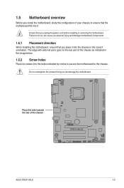
... so can cause you physical injury and damage motherboard components. 1.5.1 Placement direction When installing the motherboard, ensure that you unplug the power cord before installing or removing the motherboard. 1.5 Motherboard overview Before you install the motherboard, study the configuration of your chassis to ensure...orientation. Ensure that the motherboard fits into it into the chassis in the image below. 1.5.2 Screw holes Place six screws into the holes indicated by circles to secure the motherboard to the rear part of the chassis P5G41-M LE ASUS P5G41-M LE 1-5 The edge with ...
... so can cause you physical injury and damage motherboard components. 1.5.1 Placement direction When installing the motherboard, ensure that you unplug the power cord before installing or removing the motherboard. 1.5 Motherboard overview Before you install the motherboard, study the configuration of your chassis to ensure...orientation. Ensure that the motherboard fits into it into the chassis in the image below. 1.5.2 Screw holes Place six screws into the holes indicated by circles to secure the motherboard to the rear part of the chassis P5G41-M LE ASUS P5G41-M LE 1-5 The edge with ...
User Manual
Page 16
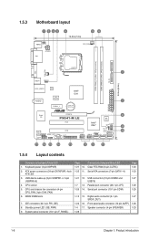
... 14. 1.5.3 Motherboard layout 1 2 53 4 19.8cm(7.8in) 56 KBMS KBPWR ATX12V DVI CPU_FAN DDR2 DIMM_A1 (64bit, 240-pin module) DDR2 DIMM_B1 (64bit, 240-pin module) PRI_IDE LGA775 7 VGA USB34 USBPW1-4 24.4cm(9.6in) LAN1_USB12 Atheros L1E Intel® G41 ICS 9LRS954 AUDIO 2 PCIEX1_1 Lithium Cell CMOS Power EATXPWR Super I/O PCIEX16 P5G41-M LE PCI1...
... 14. 1.5.3 Motherboard layout 1 2 53 4 19.8cm(7.8in) 56 KBMS KBPWR ATX12V DVI CPU_FAN DDR2 DIMM_A1 (64bit, 240-pin module) DDR2 DIMM_B1 (64bit, 240-pin module) PRI_IDE LGA775 7 VGA USB34 USBPW1-4 24.4cm(9.6in) LAN1_USB12 Atheros L1E Intel® G41 ICS 9LRS954 AUDIO 2 PCIEX1_1 Lithium Cell CMOS Power EATXPWR Super I/O PCIEX16 P5G41-M LE PCI1...
User Manual
Page 17
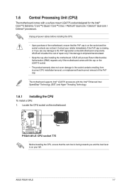
ASUS P5G41-M LE 1-7 ASUS will shoulder the cost of the PnP cap. ASUS will process Return Merchandise Authorization (RMA) requests only if the motherboard comes with the cap on the motherboard. P5G41-M LE P5G41-M LE CPU socket 775 Before installing the CPU, ensure that the PnP cap is missing, or if you and the load lever is shipment/transit-related. &#...
ASUS P5G41-M LE 1-7 ASUS will shoulder the cost of the PnP cap. ASUS will process Return Merchandise Authorization (RMA) requests only if the motherboard comes with the cap on the motherboard. P5G41-M LE P5G41-M LE CPU socket 775 Before installing the CPU, ensure that the PnP cap is missing, or if you and the load lever is shipment/transit-related. &#...
User Manual
Page 20
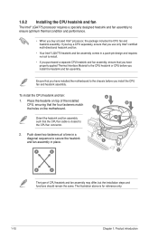
...; processor, the package includes the CPU fan and heatsink assembly. Orient the heatsink and fan assembly such that you have installed the motherboard to the chassis before you buy a CPU separately, ensure that you use only Intel®‑certified multi‑directional heatsink and ... design and requires no tool to install. • If you install the CPU fan and heatsink assembly. Place the heatsink on the motherboard. 1.6.2 Installing the CPU heatsink and fan The Intel® LGA775 processor requires a specially designed heatsink and fan assembly to ensure optimum ...
...; processor, the package includes the CPU fan and heatsink assembly. Orient the heatsink and fan assembly such that you have installed the motherboard to the chassis before you buy a CPU separately, ensure that you use only Intel®‑certified multi‑directional heatsink and ... design and requires no tool to install. • If you install the CPU fan and heatsink assembly. Place the heatsink on the motherboard. 1.6.2 Installing the CPU heatsink and fan The Intel® LGA775 processor requires a specially designed heatsink and fan assembly to ensure optimum ...

User Manual
Page 21
... fail to the connector on the motherboard. 2. Disconnect the CPU fan cable from the motherboard. CPU_FAN GND CPU FAN PWR CPU FAN IN CPU FAN PWM P5G41-M LE P5G41-M LE CPU fan connector Do not forget to disengage the heatsink and fan assembly from the connector on the motherboard labeled CPU_FAN. A B A B B A B A ASUS P5G41-M LE 1-11 Pull up two fasteners at...
... fail to the connector on the motherboard. 2. Disconnect the CPU fan cable from the motherboard. CPU_FAN GND CPU FAN PWR CPU FAN IN CPU FAN PWM P5G41-M LE P5G41-M LE CPU fan connector Do not forget to disengage the heatsink and fan assembly from the connector on the motherboard labeled CPU_FAN. A B A B B A B A ASUS P5G41-M LE 1-11 Pull up two fasteners at...

User Manual
Page 22
The figure illustrates the location of the DDR2 DIMM sockets: DIMM_A1 DIMM_B1 P5G41-M LE Channel Channel A Channel B P5G41-M LE 240-pin DDR2 DIMM sockets Sockets DIMM_A1 DIMM_B1 1-12 Chapter 1: Product introduction Carefully remove the heatsink and fan assembly from the motherboard. 5. 4. Rotate each fastener clockwise to ensure correct orientation when reinstalling. 1.7 System memory 1.7.1 Overview The motherboard comes with two Double Data Rate 2 (DDR2) Dual Inline Memory Modules (DIMM) sockets.
The figure illustrates the location of the DDR2 DIMM sockets: DIMM_A1 DIMM_B1 P5G41-M LE Channel Channel A Channel B P5G41-M LE 240-pin DDR2 DIMM sockets Sockets DIMM_A1 DIMM_B1 1-12 Chapter 1: Product introduction Carefully remove the heatsink and fan assembly from the motherboard. 5. 4. Rotate each fastener clockwise to ensure correct orientation when reinstalling. 1.7 System memory 1.7.1 Overview The motherboard comes with two Double Data Rate 2 (DDR2) Dual Inline Memory Modules (DIMM) sockets.
User Manual
Page 23
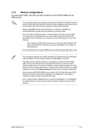
...-bit Windows® OS, when you install 4GB or more memory on the motherboard. • This motherboard does not support DIMMs made up of 256 megabits (Mb) chips or less. • This motherboard supports up to 8GB on its Serial Presence Detect (SPD), which is recommended ...ASUS P5G41-M LE 1-13 Any excess memory from a memory module. To operate at the vendor-marked or at a higher frequency, see section 2.4 Advanced menu for the dual-channel configuration. If this happens, contact your memory vendor to check the ODT value. • Due to install 4GB or more memory on the motherboard...
...-bit Windows® OS, when you install 4GB or more memory on the motherboard. • This motherboard does not support DIMMs made up of 256 megabits (Mb) chips or less. • This motherboard supports up to 8GB on its Serial Presence Detect (SPD), which is recommended ...ASUS P5G41-M LE 1-13 Any excess memory from a memory module. To operate at the vendor-marked or at a higher frequency, see section 2.4 Advanced menu for the dual-channel configuration. If this happens, contact your memory vendor to check the ODT value. • Due to install 4GB or more memory on the motherboard...
User Manual
Page 24
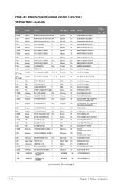
...; AET93R300B 0634 •• AET93R300B 0639 • • AENEON AET860UD0030DB08X 5 AENEON DS AET03F30DB 0730 • • (continued on the next page) 1-14 Chapter 1: Product introduction P5G41-M LE Motherboard Qualified Vendors Lists (QVL) DDR2-667 MHz capability Size 512MB 1GB 2GB 1GB 512MB 512MB 512MB 2GB 1GB 1GB 1GB 1GB 4GB (2 x 2GB) 2GB (2 x 1GB...
...; AET93R300B 0634 •• AET93R300B 0639 • • AENEON AET860UD0030DB08X 5 AENEON DS AET03F30DB 0730 • • (continued on the next page) 1-14 Chapter 1: Product introduction P5G41-M LE Motherboard Qualified Vendors Lists (QVL) DDR2-667 MHz capability Size 512MB 1GB 2GB 1GB 512MB 512MB 512MB 2GB 1GB 1GB 1GB 1GB 4GB (2 x 2GB) 2GB (2 x 1GB...

User Manual
Page 30
... severe damage to unlock a DDR2 DIMM socket. 2. Remove the DIMM from the socket. 1-20 Chapter 1: Product introduction Press the retaining clips outward to both the motherboard and the components. To install a DIMM: 1.
... severe damage to unlock a DDR2 DIMM socket. 2. Remove the DIMM from the socket. 1-20 Chapter 1: Product introduction Press the retaining clips outward to both the motherboard and the components. To install a DIMM: 1.
User Manual
Page 31
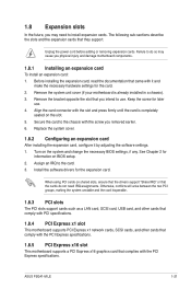
... or that the cards do so may need IRQ assignments. Assign an IRQ to install expansion cards. ASUS P5G41-M LE 1-21 Align the card connector with the screw you physical injury and damage motherboard components. 1.8.1 Installing an expansion card To install an expansion card: 1. Secure the card to the ... a LAN card, SCSI card, USB card, and other cards that comply with PCI specifications. 1.8.4 PCI Express x1 slot This motherboard supports PCI Express x1 network cards, SCSI cards, and other cards that comply with the PCI Express specifications. 1.8.5 PCI Express x16 slot This...
... or that the cards do so may need IRQ assignments. Assign an IRQ to install expansion cards. ASUS P5G41-M LE 1-21 Align the card connector with the screw you physical injury and damage motherboard components. 1.8.1 Installing an expansion card To install an expansion card: 1. Secure the card to the ... a LAN card, SCSI card, USB card, and other cards that comply with PCI specifications. 1.8.4 PCI Express x1 slot This motherboard supports PCI Express x1 network cards, SCSI cards, and other cards that comply with the PCI Express specifications. 1.8.5 PCI Express x16 slot This...
User Manual
Page 36
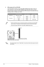
...:Orient the red markings on the IDE ribbon cable to match the covered hole on the Ultra DMA cable connector. P5G41-M LE IDE connector If any device jumper is for Ultra DMA 100/66/33 IDE devices. This prevents incorrect insertion when you connect the IDE cable. &#... removed to PIN 1. Single device Two devices Drive jumper setting Cable-Select or Master Cable-Select Master Slave Mode of the following modes to the motherboard's IDE connector, then select one of device(s) - 3. IDE connector (40-1 pin PRI_IDE) The onboard IDE connector is set as "Cable-Select," ensure that all other...
...:Orient the red markings on the IDE ribbon cable to match the covered hole on the Ultra DMA cable connector. P5G41-M LE IDE connector If any device jumper is for Ultra DMA 100/66/33 IDE devices. This prevents incorrect insertion when you connect the IDE cable. &#... removed to PIN 1. Single device Two devices Drive jumper setting Cable-Select or Master Cable-Select Master Slave Mode of the following modes to the motherboard's IDE connector, then select one of device(s) - 3. IDE connector (40-1 pin PRI_IDE) The onboard IDE connector is set as "Cable-Select," ensure that all other...


