User Manual
Page 4
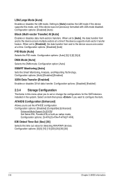
Contents 1.11 Software support 1-32 1.11.1 Installing an operating system 1-32 1.11.2 Support DVD information 1-32 Chapter 2: BIOS information 2.1 Managing and updating your BIOS 2-1 2.1.1 ASUS Update utility 2-1 2.1.2 ASUS EZ Flash 2 utility 2-2 2.1.3 ASUS CrashFree BIOS 3 utility 2-3 2.2 BIOS setup program 2-4 2.2.1 BIOS menu screen 2-5 2.2.2 Menu bar 2-5 2.2.3 Navigation keys 2-6 2.2.4 Menu items 2-6 2.2.5 Submenu items 2-6 2.2.6 Configuration fields 2-6 2.2.7 Pop-up window 2-6 2.2.8 Scroll bar 2-6 2.2.9 General help 2-6 2.3 Main menu 2-7 2.3.1 System Time [xx:xx:xx 2-7 ...
Contents 1.11 Software support 1-32 1.11.1 Installing an operating system 1-32 1.11.2 Support DVD information 1-32 Chapter 2: BIOS information 2.1 Managing and updating your BIOS 2-1 2.1.1 ASUS Update utility 2-1 2.1.2 ASUS EZ Flash 2 utility 2-2 2.1.3 ASUS CrashFree BIOS 3 utility 2-3 2.2 BIOS setup program 2-4 2.2.1 BIOS menu screen 2-5 2.2.2 Menu bar 2-5 2.2.3 Navigation keys 2-6 2.2.4 Menu items 2-6 2.2.5 Submenu items 2-6 2.2.6 Configuration fields 2-6 2.2.7 Pop-up window 2-6 2.2.8 Scroll bar 2-6 2.2.9 General help 2-6 2.3 Main menu 2-7 2.3.1 System Time [xx:xx:xx 2-7 ...
User Manual
Page 12
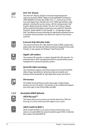
.../1066/800 Front Side Bus (FSB), PCIe 1.1, and multi-core CPUs. The Intel® G41 Express Chipset delivers optimized 3D graphics performance and support for Microsoft DirectX10. Shader Model 4.0 and OpenGL 2.1. ASUS CrashFree BIOS 3 ASUS CrashFree BIOS 3 is an auto-recovery tool that allows you to provide efficient power management for advanced operating systems. Serial ATA 3Gb/s technology This motherboard supports hard drives based on the Serial ATA (SATA) 3Gb/s storage specifications, delivering enhanced scalability...
.../1066/800 Front Side Bus (FSB), PCIe 1.1, and multi-core CPUs. The Intel® G41 Express Chipset delivers optimized 3D graphics performance and support for Microsoft DirectX10. Shader Model 4.0 and OpenGL 2.1. ASUS CrashFree BIOS 3 ASUS CrashFree BIOS 3 is an auto-recovery tool that allows you to provide efficient power management for advanced operating systems. Serial ATA 3Gb/s technology This motherboard supports hard drives based on the Serial ATA (SATA) 3Gb/s storage specifications, delivering enhanced scalability...
User Manual
Page 16
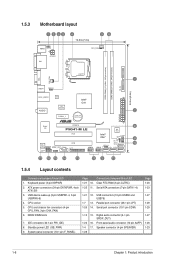
...) 8. Connectors/Jumpers/Slots/LED Clear RTC RAM (3-pin CLTRC) Serial ATA connectors (7-pin SATA 1-4) 1-21 12. Digital audio connector (4-1 pin SPDIF_OUT) 1-24 16. 1.5.3 Motherboard layout 1 2 53 4 19.8cm(7.8in) 56 KBMS KBPWR ATX12V DVI CPU_FAN DDR2 DIMM_A1 (64bit, 240-pin module) DDR2 DIMM_B1 (64bit, 240-pin module) PRI_IDE LGA775 7 VGA USB34 USBPW1-4 24.4cm(9.6in) LAN1_USB12 Atheros L1E Intel® G41 ICS 9LRS954 AUDIO 2 PCIEX1_1 Lithium Cell CMOS Power EATXPWR Super I/O PCIEX16 P5G41-M LE...
...) 8. Connectors/Jumpers/Slots/LED Clear RTC RAM (3-pin CLTRC) Serial ATA connectors (7-pin SATA 1-4) 1-21 12. Digital audio connector (4-1 pin SPDIF_OUT) 1-24 16. 1.5.3 Motherboard layout 1 2 53 4 19.8cm(7.8in) 56 KBMS KBPWR ATX12V DVI CPU_FAN DDR2 DIMM_A1 (64bit, 240-pin module) DDR2 DIMM_B1 (64bit, 240-pin module) PRI_IDE LGA775 7 VGA USB34 USBPW1-4 24.4cm(9.6in) LAN1_USB12 Atheros L1E Intel® G41 ICS 9LRS954 AUDIO 2 PCIEX1_1 Lithium Cell CMOS Power EATXPWR Super I/O PCIEX16 P5G41-M LE...
User Manual
Page 23
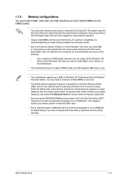
... frequency, see section 2.4 Advanced menu for manual memory frequency adjustment. • Some old-version DDR2-800 DIMMs may install a maximum of 4GB DIMMs on each slot. • The default memory operation frequency is then mapped for overclocking may install varying memory sizes in Channel A and Channel B. Install a 64-bit Windows® OS when you are using a 32-bit Windows® OS. - For effective use of memory, we recommend that you obtain memory modules from the higher-sized channel...
... frequency, see section 2.4 Advanced menu for manual memory frequency adjustment. • Some old-version DDR2-800 DIMMs may install a maximum of 4GB DIMMs on each slot. • The default memory operation frequency is then mapped for overclocking may install varying memory sizes in Channel A and Channel B. Install a 64-bit Windows® OS when you are using a 32-bit Windows® OS. - For effective use of memory, we recommend that you obtain memory modules from the higher-sized channel...
User Manual
Page 31
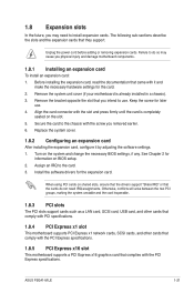
..., USB card, and other cards that comply with PCI specifications. 1.8.4 PCI Express x1 slot This motherboard supports PCI Express x1 network cards, SCSI cards, and other cards that comply with the PCI Express specifications. 1.8.5 PCI Express x16 slot This motherboard supports a PCI Express x16 graphics card that you intend to use . 4. Align the card connector with the PCI Express specifications. Turn on the slot. 5. Remove the bracket opposite the slot that complies with the slot and press firmly until the card is already installed in a chassis). 3. When using PCI cards on BIOS...
..., USB card, and other cards that comply with PCI specifications. 1.8.4 PCI Express x1 slot This motherboard supports PCI Express x1 network cards, SCSI cards, and other cards that comply with the PCI Express specifications. 1.8.5 PCI Express x16 slot This motherboard supports a PCI Express x16 graphics card that you intend to use . 4. Align the card connector with the PCI Express specifications. Turn on the slot. 5. Remove the bracket opposite the slot that complies with the slot and press firmly until the card is already installed in a chassis). 3. When using PCI cards on BIOS...
User Manual
Page 33
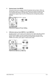
... (3-pin USBPW1-4, 3-pin USBPW5-8) Set these jumpers to +5V to wake up from S3 and S4 sleep modes (no power to wake up the computer from S1 sleep mode (CPU stopped, DRAM refreshed, system running in low power mode) using the connected USB devices. Set to +5VSB to CPU, DRAM in slow refresh, power supply in the BIOS. USBPW1-4 12 23 +5V +5VSB (Default) USBPW5-8 P5G41-M LE 12 23 +5V +5VSB (Default) P5G41-M LE USB Device Wake Up ASUS P5G41-M LE 1-23 2. KBPWR 12 23 +5V +5VSB (Default) P5G41-M LE P5G41-M LE Keyboard Power Setting...
... (3-pin USBPW1-4, 3-pin USBPW5-8) Set these jumpers to +5V to wake up from S3 and S4 sleep modes (no power to wake up the computer from S1 sleep mode (CPU stopped, DRAM refreshed, system running in low power mode) using the connected USB devices. Set to +5VSB to CPU, DRAM in slow refresh, power supply in the BIOS. USBPW1-4 12 23 +5V +5VSB (Default) USBPW5-8 P5G41-M LE 12 23 +5V +5VSB (Default) P5G41-M LE USB Device Wake Up ASUS P5G41-M LE 1-23 2. KBPWR 12 23 +5V +5VSB (Default) P5G41-M LE P5G41-M LE Keyboard Power Setting...
User Manual
Page 42
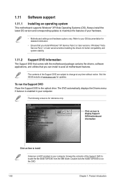
.... The contents of the Support DVD are subject to maximize the features of the Support DVD to the optical drive. The following screen is for better compatibility and system stability. 1.11.2 Support DVD information The Support DVD that comes with the motherboard package contains the drivers, software applications, and utilities that you can install to run the Support DVD Place the Support DVD to locate the file ASSETUP.EXE from the BIN...
.... The contents of the Support DVD are subject to maximize the features of the Support DVD to the optical drive. The following screen is for better compatibility and system stability. 1.11.2 Support DVD information The Support DVD that comes with the motherboard package contains the drivers, software applications, and utilities that you can install to run the Support DVD Place the Support DVD to locate the file ASSETUP.EXE from the BIN...
User Manual
Page 43
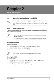
... Drivers menu appears. 2. Quit all Windows® applications before you need to manage, save, and update the motherboard BIOS in Windows® environment. • ASUS Update requires an Internet connection either through a network or an Internet Service Provider (ISP). • This utility is available in the support DVD that comes with the motherboard package. From the dropdown list, select any of the original motherboard BIOS file to a USB flash disk in case you update the BIOS using...
... Drivers menu appears. 2. Quit all Windows® applications before you need to manage, save, and update the motherboard BIOS in Windows® environment. • ASUS Update requires an Internet connection either through a network or an Internet Service Provider (ISP). • This utility is available in the support DVD that comes with the motherboard package. From the dropdown list, select any of the original motherboard BIOS file to a USB flash disk in case you update the BIOS using...
User Manual
Page 45
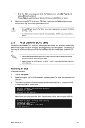
... connect the SATA cable to the optical drive or USB port. 3. When the correct BIOS file is found, EZ Flash 2 performs the BIOS update process and automatically reboots the system when done. • Only a USB flash disk with FAT 32/16 format and single partition can update a corrupted BIOS file using the motherboard support DVD or a USB flash disk that allows you to prevent system boot failure! 2.1.3 ASUS CrashFree BIOS 3 utility The ASUS CrashFree BIOS 3 is found , the utility reads the BIOS file and starts...
... connect the SATA cable to the optical drive or USB port. 3. When the correct BIOS file is found, EZ Flash 2 performs the BIOS update process and automatically reboots the system when done. • Only a USB flash disk with FAT 32/16 format and single partition can update a corrupted BIOS file using the motherboard support DVD or a USB flash disk that allows you to prevent system boot failure! 2.1.3 ASUS CrashFree BIOS 3 utility The ASUS CrashFree BIOS 3 is found , the utility reads the BIOS file and starts...

User Manual
Page 47
... 1985-2008, American Megatrends, Inc. • The default BIOS settings for this motherboard. 2.2.1 BIOS menu screen Menu items Menu bar Main Advanced Power Configuration fields BIOS SETUP UTILITY Boot Tools Exit General help System Time [00:31:48] System Date [Mon 01/14/2002] Use [ENTER], [TAB] or [SHIFT-TAB] to configure system Time. For changing the system boot configuration. ASUS P5G41-M LE 2-5 If the system becomes unstable after changing any BIOS settings, load the default settings to ensure optimum performance.
... 1985-2008, American Megatrends, Inc. • The default BIOS settings for this motherboard. 2.2.1 BIOS menu screen Menu items Menu bar Main Advanced Power Configuration fields BIOS SETUP UTILITY Boot Tools Exit General help System Time [00:31:48] System Date [Mon 01/14/2002] Use [ENTER], [TAB] or [SHIFT-TAB] to configure system Time. For changing the system boot configuration. ASUS P5G41-M LE 2-5 If the system becomes unstable after changing any BIOS settings, load the default settings to ensure optimum performance.
User Manual
Page 48
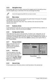
... right corner of the menu screen is user- Pop-up window with the configuration options for that do not fit on the screen. Some of a menu screen when there are the navigation keys for the menu items. If an item is a brief description of the field opposite the item. Main Advanced BIOS SETUP UTILITY Power Boot Tools Exit Suspend Mode ACPI Version Features ACPI APIC support APM Configuration Hardware Monitor [Auto] [Disabled] [EDniOsapabtbilloendesd] Enabled Use [ENTER], [TAB] or [SHIFT...
... right corner of the menu screen is user- Pop-up window with the configuration options for that do not fit on the screen. Some of a menu screen when there are the navigation keys for the menu items. If an item is a brief description of the field opposite the item. Main Advanced BIOS SETUP UTILITY Power Boot Tools Exit Suspend Mode ACPI Version Features ACPI APIC support APM Configuration Hardware Monitor [Auto] [Disabled] [EDniOsapabtbilloendesd] Enabled Use [ENTER], [TAB] or [SHIFT...
User Manual
Page 49
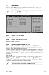
..., and SMART monitoring). Select ARMD (ATAPI Removable Media Device) if your device is installed in the system. 2.3 Main menu When you enter the BIOS Setup program, the Main menu screen appears, giving you an overview of IDE drive. These items show N/A if no IDE/SATA device is either a ZIP, LS-120, or MO drive. Type [Auto] Selects the type of the basic system information. Setting to display the IDE/SATA device information. Storage Configuration System Information Select Screen Select Item +- Change Field...
..., and SMART monitoring). Select ARMD (ATAPI Removable Media Device) if your device is installed in the system. 2.3 Main menu When you enter the BIOS Setup program, the Main menu screen appears, giving you an overview of IDE drive. These items show N/A if no IDE/SATA device is either a ZIP, LS-120, or MO drive. Type [Auto] Selects the type of the basic system information. Setting to display the IDE/SATA device information. Storage Configuration System Information Select Screen Select Item +- Change Field...
User Manual
Page 50
... options: [Disabled] [Enabled] 2.3.4 Storage Configuration The items in the system. Configuration options: [S-ATA] [S-ATA+P-ATA] [P-ATA]. Configuration options: [Disabled] [Auto] PIO Mode [Auto] Selects the PIO mode. Configuration option: [Auto] SMART Monitoring [Auto] Sets the Smart Monitoring, Analysis, and Reporting Technology. When set to [Disabled], the data transfer from and to the device occurs one sector at a time if the device supports multi-sector transfer feature. Configuration options: [Disabled] [Compatible] [Enhanced] Enhanced Mode Support On [S-ATA] Set Serial...
... options: [Disabled] [Enabled] 2.3.4 Storage Configuration The items in the system. Configuration options: [S-ATA] [S-ATA+P-ATA] [P-ATA]. Configuration options: [Disabled] [Auto] PIO Mode [Auto] Selects the PIO mode. Configuration option: [Auto] SMART Monitoring [Auto] Sets the Smart Monitoring, Analysis, and Reporting Technology. When set to [Disabled], the data transfer from and to the device occurs one sector at a time if the device supports multi-sector transfer feature. Configuration options: [Disabled] [Compatible] [Enhanced] Enhanced Mode Support On [S-ATA] Set Serial...
User Manual
Page 51
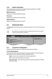
...caution when changing the settings of the general system specifications. loads overclocking profiles with optimal parameters for the CPU and other system devices. System Memory Displays the auto-detected system memory. 2.4 Advanced menu The Advanced menu items allow you to change the settings for stability when overclocking. Main Advanced Power BIOS SETUP UTILITY Boot Tools Exit JumperFree Configuration CPU Configuration Chipset Onboard Devices Configuration USB Configuration PCIPnP Adjust System frequency/voltage. 2.4.1 JumperFree Configuration The items in this menu allows you...
...caution when changing the settings of the general system specifications. loads overclocking profiles with optimal parameters for the CPU and other system devices. System Memory Displays the auto-detected system memory. 2.4 Advanced menu The Advanced menu items allow you to change the settings for stability when overclocking. Main Advanced Power BIOS SETUP UTILITY Boot Tools Exit JumperFree Configuration CPU Configuration Chipset Onboard Devices Configuration USB Configuration PCIPnP Adjust System frequency/voltage. 2.4.1 JumperFree Configuration The items in this menu allows you...
User Manual
Page 54
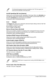
... the DIMM sockets. Protect Audio Video Path Mode [Lite] This item is not user- When set to [Enabled], you install 64-bit operating system. North Bridge Configuration Memory Remap Feature [Enabled] Allows you to use as the primary boot device. Intel(R) SpeedStep(TM) Tech [Enabled] Allows you to enabled or disable the remapping of system memory used by SPD. Select an item then press to display the submenu. Configuration options: [IGD] [PCI/IGD] [PCI/PEG...
... the DIMM sockets. Protect Audio Video Path Mode [Lite] This item is not user- When set to [Enabled], you install 64-bit operating system. North Bridge Configuration Memory Remap Feature [Enabled] Allows you to use as the primary boot device. Intel(R) SpeedStep(TM) Tech [Enabled] Allows you to enabled or disable the remapping of system memory used by SPD. Select an item then press to display the submenu. Configuration options: [IGD] [PCI/IGD] [PCI/PEG...

User Manual
Page 55
...EPP Version [1.9] Appears only when the Parallel Port Mode item is set to Enabled. If High Definition Audio Front Panel used, set the audio controller. Configuration options: [AC97] [HD Audio] 2.4.4 Onboard Devices Configuration Onboard LAN [Enabled] Allows you to display the configuration options. Configuration options: [IRQ5] [IRQ7] 2.4.5 USB Configuration The items in the onboard LAN controller. Select an item then press to enable or disable the onboard LAN controller. South Bridge Configuration Audio Controller [Enabled] Allows you to set this menu allows you to change the USB...
...EPP Version [1.9] Appears only when the Parallel Port Mode item is set to Enabled. If High Definition Audio Front Panel used, set the audio controller. Configuration options: [AC97] [HD Audio] 2.4.4 Onboard Devices Configuration Onboard LAN [Enabled] Allows you to display the configuration options. Configuration options: [IRQ5] [IRQ7] 2.4.5 USB Configuration The items in the onboard LAN controller. Select an item then press to enable or disable the onboard LAN controller. South Bridge Configuration Audio Controller [Enabled] Allows you to set this menu allows you to change the USB...
User Manual
Page 56
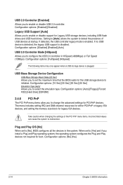
...boot. When set to [No], BIOS configures all the devices in HiSpeed (480Mbps) or Full Speed (12Mbps). Configuration options: [Auto] [Floppy] [Forced FDD] [Hard Disk] [CDROM] 2.4.6 PCI PnP The PCI PnP menu items allow you to enable or disable support for PCI/PnP devices. Configuration options: [Enabled] [Disabled] Legacy USB Support [Auto] Allows you to change the advanced settings for Legacy USB storage devices, including USB flash drives and USB hard drives. If no USB device is detected, the legacy USB support is disabled. USB Mass Storage Device Configuration USB Mass Storage Reset...
...boot. When set to [No], BIOS configures all the devices in HiSpeed (480Mbps) or Full Speed (12Mbps). Configuration options: [Auto] [Floppy] [Forced FDD] [Hard Disk] [CDROM] 2.4.6 PCI PnP The PCI PnP menu items allow you to enable or disable support for PCI/PnP devices. Configuration options: [Enabled] [Disabled] Legacy USB Support [Auto] Allows you to change the advanced settings for Legacy USB storage devices, including USB flash drives and USB hard drives. If no USB device is detected, the legacy USB support is disabled. USB Mass Storage Device Configuration USB Mass Storage Reset...

User Manual
Page 57
.... Configuration options: [Disabled] [Enabled] 2.5.3 ACPI APIC Support [Enabled] Allows you to its working state exactly where it was before the AC power loss. When signaled by OS. 2.5.2 ACPI 2.0 Support [Enabled] Allows you to enter the ACPI S1 (Power on AC Power Loss [Power Off] When set to [Power Off], the system goes into either off . [Auto] - Main Advanced Power BIOS SETUP UTILITY Boot Tools Exit Suspend Mode ACPI 2.0 Support ACPI APIC Support Anti Surgy Support [Auto] [Disabled] [Enabled] [Enabled] APM Configuration Hardware Monitor Select the ACPI state used for...
.... Configuration options: [Disabled] [Enabled] 2.5.3 ACPI APIC Support [Enabled] Allows you to its working state exactly where it was before the AC power loss. When signaled by OS. 2.5.2 ACPI 2.0 Support [Enabled] Allows you to enter the ACPI S1 (Power on AC Power Loss [Power Off] When set to [Power Off], the system goes into either off . [Auto] - Main Advanced Power BIOS SETUP UTILITY Boot Tools Exit Suspend Mode ACPI 2.0 Support ACPI APIC Support Anti Surgy Support [Auto] [Disabled] [Enabled] [Enabled] APM Configuration Hardware Monitor Select the ACPI state used for...
User Manual
Page 59
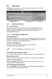
...boot options. AddOn ROM Display Mode [Force BIOS] Sets the display mode for the NumLock. 2.6 Boot menu The Boot menu items allow you set the CD-ROM drive as the first boot. The number of devices installed in the system. A virtual floppy disk drive (Floppy Drive B: ) may appear when you to enable or disable the full screen logo display feature. Configuration options: [Removable Dev.] [Hard Drive] [ATAPI CD-ROM] [Disabled] 2.6.2 Boot Settings Configuration Quick Boot [Enabled] Enabling this item to [Enabled] to display the sub-menu. Main Advanced Power BIOS SETUP UTILITY Boot...
...boot options. AddOn ROM Display Mode [Force BIOS] Sets the display mode for the NumLock. 2.6 Boot menu The Boot menu items allow you set the CD-ROM drive as the first boot. The number of devices installed in the system. A virtual floppy disk drive (Floppy Drive B: ) may appear when you to enable or disable the full screen logo display feature. Configuration options: [Removable Dev.] [Hard Drive] [ATAPI CD-ROM] [Disabled] 2.6.2 Boot Settings Configuration Quick Boot [Enabled] Enabling this item to [Enabled] to display the sub-menu. Main Advanced Power BIOS SETUP UTILITY Boot...
User Manual
Page 61
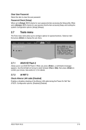
... user password both when accessing Setup and booting the system. Main Advanced Power BIOS SETUP UTILITY Boot Tools Exit ASUS EZ Flash 2 AI NET 2 Press ENTER to run ASUS EZ Flash 2. Use the left/right arrow key to select between [Yes] or [No], then press to select and update BIOS. Configuration options: [Disabled] [Enabled] ASUS P5G41-M LE 2-19 Configuration options: [Setup] [Always] 2.7 Tools menu The Tools menu items allow you press , a confirmation message appears. See section 2.1.2 for details. 2.7.2 AI NET 2 Check Atheros LAN cable [Disabled] Enables...
... user password both when accessing Setup and booting the system. Main Advanced Power BIOS SETUP UTILITY Boot Tools Exit ASUS EZ Flash 2 AI NET 2 Press ENTER to run ASUS EZ Flash 2. Use the left/right arrow key to select between [Yes] or [No], then press to select and update BIOS. Configuration options: [Disabled] [Enabled] ASUS P5G41-M LE 2-19 Configuration options: [Setup] [Always] 2.7 Tools menu The Tools menu items allow you press , a confirmation message appears. See section 2.1.2 for details. 2.7.2 AI NET 2 Check Atheros LAN cable [Disabled] Enables...


