
User Guide
Page 11
... BIOS 2 ASUS Multi-Language BIOS ASUS MyLogo2™ ASUS EZ FLash AMI BIOS, 8 MB FWH, Green, PnP, DMI2.0a, WfM2.0., ACPI 2.0A, SMBIOS 2.3 1 x PS/2 keyboard port 1 x PS/2 mouse port 2 x USB 2.0 ports 1 x Serial (COM1) port 2 x LAN (RJ-45) ports 1 x VGA port 1 x Parallel port 1 x Floppy disk drive connector 1x IDE connector 4 x Serial ATA connectors 1 x Ultra320 SCSI connector (for P5CR-LS...
... BIOS 2 ASUS Multi-Language BIOS ASUS MyLogo2™ ASUS EZ FLash AMI BIOS, 8 MB FWH, Green, PnP, DMI2.0a, WfM2.0., ACPI 2.0A, SMBIOS 2.3 1 x PS/2 keyboard port 1 x PS/2 mouse port 2 x USB 2.0 ports 1 x Serial (COM1) port 2 x LAN (RJ-45) ports 1 x VGA port 1 x Parallel port 1 x Floppy disk drive connector 1x IDE connector 4 x Serial ATA connectors 1 x Ultra320 SCSI connector (for P5CR-LS...

User Guide
Page 23
ASUS P5CR-L(S) 2-3 30.5cm (12in) 2.2.3 Motherboard layout PS/2KBMS T: Mouse B: Keyboard USB12 ...DDR2 DIMM_A2 (64 bit,240-pin module) DDR2 DIMM_A1 (64 bit,240-pin module) PARALLEL PORT ® P5CR-LS VGA1 LAN1 LAN2 LGA775 Intel® E7221 Broadcom BCM5721 LAN_EN1 Broadcom BCM5721 LAN_EN2 FM_CPU1 CPU_FAN1 PCIX1 PCIX2 PCIE3 ATI... RAGE XL VGA Controller VGA_EN1 SB_PWR1 8Mbit Flash BIOS PCI4 COM2 PCI5 Super I/O BPSMB1 CR2032 3V Lithium Cell CMOS Power BUZZ1 TRPWR1 CLRTC1 BMCSOCKET1 Intel ®...
ASUS P5CR-L(S) 2-3 30.5cm (12in) 2.2.3 Motherboard layout PS/2KBMS T: Mouse B: Keyboard USB12 ...DDR2 DIMM_A2 (64 bit,240-pin module) DDR2 DIMM_A1 (64 bit,240-pin module) PARALLEL PORT ® P5CR-LS VGA1 LAN1 LAN2 LGA775 Intel® E7221 Broadcom BCM5721 LAN_EN1 Broadcom BCM5721 LAN_EN2 FM_CPU1 CPU_FAN1 PCIX1 PCIX2 PCIE3 ATI... RAGE XL VGA Controller VGA_EN1 SB_PWR1 8Mbit Flash BIOS PCI4 COM2 PCI5 Super I/O BPSMB1 CR2032 3V Lithium Cell CMOS Power BUZZ1 TRPWR1 CLRTC1 BMCSOCKET1 Intel ®...

User Guide
Page 24
...controller setting (3-pin LAN_EN2) 7. Parallel port 3. Serial (COM1) port 6. DDR2 DIMM sockets 3. Keyboard power (3-pin KBPWR1) 5. SCSI controller setting (3-pin SCSI_EN1) [for P5CR-LS only] 8. CPU fan pin selection (3-pin FM_CPU1, FM_CPU2) 3. LAN 2 (RJ-45) port Page 2-25 2-25 2-25 2-25 2-25 2-25 2-25 2-25 ...2. VGA port 7. Gigabit LAN controller setting (3-pin LAN_EN1) 6. PS/2 keyboard port 4. USB device wake-up (3-pin USBPW12, USBPW34) 4. BIOS recovery (3-pin RECOVERY1) Page 2-19 2-20 2-20 2-21 2-21 2-22 2-22 2-23 2-24 Rear panel connectors 1. CPU sockets 2.
...controller setting (3-pin LAN_EN2) 7. Parallel port 3. Serial (COM1) port 6. DDR2 DIMM sockets 3. Keyboard power (3-pin KBPWR1) 5. SCSI controller setting (3-pin SCSI_EN1) [for P5CR-LS only] 8. CPU fan pin selection (3-pin FM_CPU1, FM_CPU2) 3. LAN 2 (RJ-45) port Page 2-25 2-25 2-25 2-25 2-25 2-25 2-25 2-25 ...2. VGA port 7. Gigabit LAN controller setting (3-pin LAN_EN1) 6. PS/2 keyboard port 4. USB device wake-up (3-pin USBPW12, USBPW34) 4. BIOS recovery (3-pin RECOVERY1) Page 2-19 2-20 2-20 2-21 2-21 2-22 2-22 2-23 2-24 Rear panel connectors 1. CPU sockets 2.

User Guide
Page 39
...RAM (CLRTC1) This jumper allows you to re-enter data. Removing the cap will cause system boot failure! ® P5CR-LS P5CR-L(S) Clear RTC RAM CLRTC1 2 1 Normal (Default) 3 2 Clear CMOS ASUS P5CR-L(S) 2-19 You can clear the CMOS memory of date, time, and system setup parameters by erasing the CMOS RTC RAM... data. Hold down the key during the boot process and enter BIOS setup to clear the Real Time Clock (RTC) RAM ...
...RAM (CLRTC1) This jumper allows you to re-enter data. Removing the cap will cause system boot failure! ® P5CR-LS P5CR-L(S) Clear RTC RAM CLRTC1 2 1 Normal (Default) 3 2 Clear CMOS ASUS P5CR-L(S) 2-19 You can clear the CMOS memory of date, time, and system setup parameters by erasing the CMOS RTC RAM... data. Hold down the key during the boot process and enter BIOS setup to clear the Real Time Clock (RTC) RAM ...

User Guide
Page 41
... allow you to activate the Gigabit LAN feature. ® P5CR-LS LAN_EN1 2 1 Enable (Default) 3 2 Disable P5CR-L(S) LAN_EN1 setting ASUS P5CR-L(S) 2-21 Keyboard power (3-pin KBPWR1) This jumper allows you press a key on the +5VSB lead, and a corresponding setting in the BIOS. ® P5CR-LS KBPWR1 12 23 +5V (Default) +5VSB P5CR-L(S) Keyboard power setting 5 . Set this jumper to pins...
... allow you to activate the Gigabit LAN feature. ® P5CR-LS LAN_EN1 2 1 Enable (Default) 3 2 Disable P5CR-L(S) LAN_EN1 setting ASUS P5CR-L(S) 2-21 Keyboard power (3-pin KBPWR1) This jumper allows you press a key on the +5VSB lead, and a corresponding setting in the BIOS. ® P5CR-LS KBPWR1 12 23 +5V (Default) +5VSB P5CR-L(S) Keyboard power setting 5 . Set this jumper to pins...

User Guide
Page 44
.... Insert a floppy disk with the original or updated BIOS file. 4. When finished, shut down the < D e l > key during the boot process and enter BIOS setup to recover your computer. 7. BIOS recovery (3-pin RECOVERY1) This jumper allows you to re-enter data. ® P5CR-LS RECOVERY1 32 21 BIOS recovery P5CR-L(S) BIOS recovery setting Normal (Default) 2-24 Chapter 2: Hardware information...
.... Insert a floppy disk with the original or updated BIOS file. 4. When finished, shut down the < D e l > key during the boot process and enter BIOS setup to recover your computer. 7. BIOS recovery (3-pin RECOVERY1) This jumper allows you to re-enter data. ® P5CR-LS RECOVERY1 32 21 BIOS recovery P5CR-L(S) BIOS recovery setting Normal (Default) 2-24 Chapter 2: Hardware information...

User Guide
Page 48
...Use only two Serial ATA RAID connectors for details. ® P5CR-LS SATA4 SATA2 GND RSATA_TXP4 RSATA_TXN4 GND RSATA_RXP4 RSATA_RXN4 GND GND RSATA_TXP2 RSATA_TXN2 GND RSATA_RXP2 RSATA_RXN2 GND SATA3 SATA1 P5CR-L(S) SATA connectors GND RSATA_TXP3 RSATA_TXN3 GND RSATA_RXP3 RSATA_RXN3 GND GND ...RSATA_TXP1 RSATA_TXN1 GND RSATA_RXP1 RSATA_RXN1 GND Important notes on Serial ATA • You must install Windows® 2000 Service Pack 4 or the Windows® 2003 before using the connectors in the BIOS...
...Use only two Serial ATA RAID connectors for details. ® P5CR-LS SATA4 SATA2 GND RSATA_TXP4 RSATA_TXN4 GND RSATA_RXP4 RSATA_RXN4 GND GND RSATA_TXP2 RSATA_TXN2 GND RSATA_RXP2 RSATA_RXN2 GND SATA3 SATA1 P5CR-L(S) SATA connectors GND RSATA_TXP3 RSATA_TXN3 GND RSATA_RXP3 RSATA_RXN3 GND GND ...RSATA_TXP1 RSATA_TXN1 GND RSATA_RXP1 RSATA_RXN1 GND Important notes on Serial ATA • You must install Windows® 2000 Service Pack 4 or the Windows® 2003 before using the connectors in the BIOS...

User Guide
Page 56
...the HDD. • System warning speaker (Orange 4-pin SPKROUT) This 4-pin connector is in sleep or soft-off mode depending on the BIOS settings. The speaker allows you turn on or puts the system in sleep mode. • Hard disk drive activity LED (Red 2-pin ...System panel connector (20-pin PANEL1) This connector supports several chassis-mounted functions. ® P5CR-LS POWERLED+ GND POWERLEDMLED+ MLEDNC +5V GND GND SPKROUT HDLED+ HDLEDNMIBTN# GND POWERBTN# GND NC RESETBTN# GND PANEL1 P5CR-L(S) System panel connector The sytem panel connector is color-coded for easy connection. •...
...the HDD. • System warning speaker (Orange 4-pin SPKROUT) This 4-pin connector is in sleep or soft-off mode depending on the BIOS settings. The speaker allows you turn on or puts the system in sleep mode. • Hard disk drive activity LED (Red 2-pin ...System panel connector (20-pin PANEL1) This connector supports several chassis-mounted functions. ® P5CR-LS POWERLED+ GND POWERLEDMLED+ MLEDNC +5V GND GND SPKROUT HDLED+ HDLEDNMIBTN# GND POWERBTN# GND NC RESETBTN# GND PANEL1 P5CR-L(S) System panel connector The sytem panel connector is color-coded for easy connection. •...
User Guide
Page 64
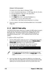
... D is your optical drive letter. R O M for P5CR-LS model, and P 5 C R L . c. e. R O M for P5CR-L model. 4. b. Use the appropriate BIOS file depending on your motherboard model (e.g. P 5 C R L S . Copy the original or the latest motherboard BIOS file to the bootable floppy disk. 4.1.2 ASUS EZ Flash utility The ASUS EZ Flash feature allows you to update the BIOS without having to P 5 C R L S . Insert a formatted, high...
... D is your optical drive letter. R O M for P5CR-LS model, and P 5 C R L . c. e. R O M for P5CR-L model. 4. b. Use the appropriate BIOS file depending on your motherboard model (e.g. P 5 C R L S . Copy the original or the latest motherboard BIOS file to the bootable floppy disk. 4.1.2 ASUS EZ Flash utility The ASUS EZ Flash feature allows you to update the BIOS without having to P 5 C R L S . Insert a formatted, high...

User Guide
Page 77
...supports multi-sector transfer feature. 4.3.4 Primary, Third, and Fourth IDE Master/Slave While entering Setup, the BIOS automatically detects the presence of IDE drive. The BIOS automatically detects the values opposite the dimmed items (Device, Vendor, Size, LBA Mode, Block Mode, ...PIO Mode, Async DMA, Ultra DMA, and SMART monitoring). Select ARMD (ATAPI Removable Media Device) if your device is either a ZIP, LS-120, or MO drive. Configuration options: [Disabled] [Auto] ASUS P5CR...
...supports multi-sector transfer feature. 4.3.4 Primary, Third, and Fourth IDE Master/Slave While entering Setup, the BIOS automatically detects the presence of IDE drive. The BIOS automatically detects the values opposite the dimmed items (Device, Vendor, Size, LBA Mode, Block Mode, ...PIO Mode, Async DMA, Ultra DMA, and SMART monitoring). Select ARMD (ATAPI Removable Media Device) if your device is either a ZIP, LS-120, or MO drive. Configuration options: [Disabled] [Auto] ASUS P5CR...

User Guide
Page 86
Configuration options: [Disabled] [Enabled] [Auto] Onboard SCSI Boot ROM [Enabled] (This item is for model P5CR-LS only) Allows you to enable or disable the ASUS Hyper Path 2 feature. Configuration options: [Auto] [Disabled] Hyper Path 2 [Auto] Allows you to enable or disable the onboard SCSI boot ROM. DRAM ECC Mode [Auto] Allows you to enable or disable the onboard LAN boot ROM. Configuration options: [Disabled] [Enabled] Onboard LAN Boot ROM [Enabled] Allows you to enable or disable DRAM timing. Configuration options: [Disabled] [Enabled] 4-24 Chapter 4: BIOS setup
Configuration options: [Disabled] [Enabled] [Auto] Onboard SCSI Boot ROM [Enabled] (This item is for model P5CR-LS only) Allows you to enable or disable the ASUS Hyper Path 2 feature. Configuration options: [Auto] [Disabled] Hyper Path 2 [Auto] Allows you to enable or disable the onboard SCSI boot ROM. DRAM ECC Mode [Auto] Allows you to enable or disable the onboard LAN boot ROM. Configuration options: [Disabled] [Enabled] Onboard LAN Boot ROM [Enabled] Allows you to enable or disable DRAM timing. Configuration options: [Disabled] [Enabled] 4-24 Chapter 4: BIOS setup
User Guide
Page 127
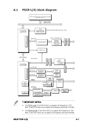
...W83792AD Fan Power Supply EEPROM System information W83627EHF-A PS2 KB/MS Floppy Serial Port Parallel Port BIOS Flash 8 Mbit Mini PCI (BMC) * IMPORTANT NOTES: • For P5CR-L only: If one PCI-X slot is occupied, the frequency is 133 MHz. If ... slots are occupied, the frequency becomes 100 MHz. • For P5CR-LS only: If one PCI-X slot is occupied, the frequency is 100 MHz. PCI Slot 1 PCI Slot 2 A.1 P5CR-L(S) block diagram Intel® Pentium® 4 Processor in the 775...Intel 6702PXH PCI-X 133 MHz bus* Adaptec AIC-7901 U320 SCSI (optional) VGA-Conn. ASUS P5CR-L(S) A-1
...W83792AD Fan Power Supply EEPROM System information W83627EHF-A PS2 KB/MS Floppy Serial Port Parallel Port BIOS Flash 8 Mbit Mini PCI (BMC) * IMPORTANT NOTES: • For P5CR-L only: If one PCI-X slot is occupied, the frequency is 133 MHz. If ... slots are occupied, the frequency becomes 100 MHz. • For P5CR-LS only: If one PCI-X slot is occupied, the frequency is 100 MHz. PCI Slot 1 PCI Slot 2 A.1 P5CR-L(S) block diagram Intel® Pentium® 4 Processor in the 775...Intel 6702PXH PCI-X 133 MHz bus* Adaptec AIC-7901 U320 SCSI (optional) VGA-Conn. ASUS P5CR-L(S) A-1

