
User Guide
Page 2
..., without intent to the owners' benefit, without the express written permission of ASUSTeK COMPUTER INC. ("ASUS"). IN NO EVENT SHALL ASUS, ITS DIRECTORS, OFFICERS, EMPLOYEES OR AGENTS BE LIABLE FOR ANY INDIRECT, SPECIAL, INCIDENTAL, OR CONSEQUENTIAL... BUT NOT LIMITED TO THE IMPLIED WARRANTIES OR CONDITIONS OF MERCHANTABILITY OR FITNESS FOR A PARTICULAR PURPOSE. ASUS ASSUMES NO RESPONSIBILITY OR LIABILITY FOR ANY ERRORS OR INACCURACIES THAT MAY APPEAR IN THIS MANUAL, INCLUDING THE... USE ONLY, AND ARE SUBJECT TO CHANGE AT ANY TIME WITHOUT NOTICE, AND SHOULD NOT BE CONSTRUED AS A COMMITMENT BY...
..., without intent to the owners' benefit, without the express written permission of ASUSTeK COMPUTER INC. ("ASUS"). IN NO EVENT SHALL ASUS, ITS DIRECTORS, OFFICERS, EMPLOYEES OR AGENTS BE LIABLE FOR ANY INDIRECT, SPECIAL, INCIDENTAL, OR CONSEQUENTIAL... BUT NOT LIMITED TO THE IMPLIED WARRANTIES OR CONDITIONS OF MERCHANTABILITY OR FITNESS FOR A PARTICULAR PURPOSE. ASUS ASSUMES NO RESPONSIBILITY OR LIABILITY FOR ANY ERRORS OR INACCURACIES THAT MAY APPEAR IN THIS MANUAL, INCLUDING THE... USE ONLY, AND ARE SUBJECT TO CHANGE AT ANY TIME WITHOUT NOTICE, AND SHOULD NOT BE CONSTRUED AS A COMMITMENT BY...

User Guide
Page 4
... 3: Powering up 3.1 Starting up for the first time 3-1 3.2 Powering off the computer 3-2 3.2.1 Using the OS shut down function 3-2 3.2.2 Using the dual function power switch 3-2 Chapter 4: BIOS setup 4.1 Managing and updating your BIOS 4-1 4.1.1 Creating a bootable floppy disk 4-1 4.1.2 ASUS EZ Flash utility 4-2 4.1.3 AFUDOS utility 4-3 4.1.4 ASUS CrashFree BIOS 2 utility 4-6 4.1.5 ASUS Update utility 4-8 4.2 BIOS setup program 4-11 4.2.1 BIOS...
... 3: Powering up 3.1 Starting up for the first time 3-1 3.2 Powering off the computer 3-2 3.2.1 Using the OS shut down function 3-2 3.2.2 Using the dual function power switch 3-2 Chapter 4: BIOS setup 4.1 Managing and updating your BIOS 4-1 4.1.1 Creating a bootable floppy disk 4-1 4.1.2 ASUS EZ Flash utility 4-2 4.1.3 AFUDOS utility 4-3 4.1.4 ASUS CrashFree BIOS 2 utility 4-6 4.1.5 ASUS Update utility 4-8 4.2 BIOS setup program 4-11 4.2.1 BIOS...

User Guide
Page 30
CPU_FAN2 CPU_FAN2 FANOUT4 FANPWR2 GND CPU_FAN1 CPU_FAN1 ® P5CR-LS GND FANPWR2 FANOUT4 P5CR-L(S) CPU fan connectors • Do not forget to secure the B heatsink and fan assembly in a diagonal sequence to connect the CPU fan connector! Push down two fasteners at a time in A place. Connect the CPU fan cable to do so may...
CPU_FAN2 CPU_FAN2 FANOUT4 FANPWR2 GND CPU_FAN1 CPU_FAN1 ® P5CR-LS GND FANPWR2 FANOUT4 P5CR-L(S) CPU fan connectors • Do not forget to secure the B heatsink and fan assembly in a diagonal sequence to connect the CPU fan connector! Push down two fasteners at a time in A place. Connect the CPU fan cable to do so may...

User Guide
Page 31
A B A B B A ASUS P5CR-L(S) 2-11 Pull up two fasteners at a time in a diagonal sequence to disengage the heatsink B and fan assembly from the connector on the motherboard. 2. Disconnect the CPU fan cable from the A motherboard. Rotate each fastener counterclockwise. 3. 2.3.3 Uninstalling the CPU heatsink and fan To uninstall the CPU heatsink and fan: 1.
A B A B B A ASUS P5CR-L(S) 2-11 Pull up two fasteners at a time in a diagonal sequence to disengage the heatsink B and fan assembly from the connector on the motherboard. 2. Disconnect the CPU fan cable from the A motherboard. Rotate each fastener counterclockwise. 3. 2.3.3 Uninstalling the CPU heatsink and fan To uninstall the CPU heatsink and fan: 1.

User Guide
Page 37
... Controller Re-direct to IRQ #9 Communications Port (COM2)* Communications Port (COM1)* IRQ holder for PCI steering* Floppy Disk Controller Printer Port (LPT1)* System CMOS/Real Time Clock IRQ holder for PCI steering* IRQ holder for PCI steering* IRQ holder for PCI steering* PS/2 Compatible Mouse Port* Numeric Data Processor Primary IDE... 5 PXIRQ0 PXIRQ4 PIRQA# PIRQE# PIRQG# PXIRQ1 PXIRQ2 PXIRQ3 PXIRQ5 PXIRQ6 PXIRQ7 PIRQF# PIRQG# PIRQH# PIRQH# PIRQE# PIRQF# PXREQ0 PXGNT0 PXREQ1 PXGNT1 REQ0 GNT0# REQ1# GNT1# ASUS P5CR-L(S) 2-17
... Controller Re-direct to IRQ #9 Communications Port (COM2)* Communications Port (COM1)* IRQ holder for PCI steering* Floppy Disk Controller Printer Port (LPT1)* System CMOS/Real Time Clock IRQ holder for PCI steering* IRQ holder for PCI steering* IRQ holder for PCI steering* PS/2 Compatible Mouse Port* Numeric Data Processor Primary IDE... 5 PXIRQ0 PXIRQ4 PIRQA# PIRQE# PIRQG# PXIRQ1 PXIRQ2 PXIRQ3 PXIRQ5 PXIRQ6 PXIRQ7 PIRQF# PIRQG# PIRQH# PIRQH# PIRQE# PIRQF# PXREQ0 PXGNT0 PXREQ1 PXGNT1 REQ0 GNT0# REQ1# GNT1# ASUS P5CR-L(S) 2-17

User Guide
Page 39
...remove the cap on pins 2-3 for about 5~10 seconds, then move the cap back to clear the Real Time Clock (RTC) RAM in CMOS, which include system setup information such as system passwords. 2.6 Jumpers 1. The ...onboard button cell battery powers the RAM data in CMOS. You can clear the CMOS memory of date, time, and system setup parameters by erasing the CMOS RTC RAM data. Remove the onboard battery. 3. Keep the... power cord. 2. Removing the cap will cause system boot failure! ® P5CR-LS P5CR-L(S) Clear RTC RAM CLRTC1 2 1 Normal (Default) 3 2 Clear CMOS ASUS P5CR-L(S) 2-19
...remove the cap on pins 2-3 for about 5~10 seconds, then move the cap back to clear the Real Time Clock (RTC) RAM in CMOS, which include system setup information such as system passwords. 2.6 Jumpers 1. The ...onboard button cell battery powers the RAM data in CMOS. You can clear the CMOS memory of date, time, and system setup parameters by erasing the CMOS RTC RAM data. Remove the onboard battery. 3. Keep the... power cord. 2. Removing the cap will cause system boot failure! ® P5CR-LS P5CR-L(S) Clear RTC RAM CLRTC1 2 1 Normal (Default) 3 2 Clear CMOS ASUS P5CR-L(S) 2-19

User Guide
Page 58
Chapter summary 3 3.1 Starting up for the first time 3-1 3.2 Powering off the computer 3-2 ASUS P5CR-L(S)
Chapter summary 3 3.1 Starting up for the first time 3-1 3.2 Powering off the computer 3-2 ASUS P5CR-L(S)

User Guide
Page 59
...Two continuous beeps followed by two short beeps Two continuous beeps followed by four short beeps Error Keyboard controller error Refresh Time error No master drive detected Floppy controller failure Hardware component failure 7. After applying power, the system power LED on ... complies with the last device on , hold down the key to a power outlet that all the connections, replace the system case cover. 2. ASUS P5CR-L(S) 3-1 System power 6. 3.1 Starting up for assistance. For systems with a surge protector. 5. Follow the instructions in the following order: a....
...Two continuous beeps followed by two short beeps Two continuous beeps followed by four short beeps Error Keyboard controller error Refresh Time error No master drive detected Floppy controller failure Hardware component failure 7. After applying power, the system power LED on ... complies with the last device on , hold down the key to a power outlet that all the connections, replace the system case cover. 2. ASUS P5CR-L(S) 3-1 System power 6. 3.1 Starting up for assistance. For systems with a surge protector. 5. Follow the instructions in the following order: a....

User Guide
Page 74
... item is highlighted. 4.2.3 Navigation keys At the bottom right corner of the navigation keys differ from one screen to configure the System time. Some of a menu screen are the navigation keys for that particular menu. 4.2.1 BIOS menu screen Menu items Menu bar Configuration fields General... Third IDE Slave Fourth IDE Master Fourth IDE Slave IDE Configuration System Information [16:37:21] [Mon,10/02/2004] [1.44M, 3.5 in.] [English] [ST320410A] : [ASUS CD-S520/A] : [Not Detected] : [Not Detected] : [Not Detected] : [Not Detected] Use [ENTER], [TAB] or [SHIFT-TAB] to select items in the...
... item is highlighted. 4.2.3 Navigation keys At the bottom right corner of the navigation keys differ from one screen to configure the System time. Some of a menu screen are the navigation keys for that particular menu. 4.2.1 BIOS menu screen Menu items Menu bar Configuration fields General... Third IDE Slave Fourth IDE Master Fourth IDE Slave IDE Configuration System Information [16:37:21] [Mon,10/02/2004] [1.44M, 3.5 in.] [English] [ST320410A] : [ASUS CD-S520/A] : [Not Detected] : [Not Detected] : [Not Detected] : [Not Detected] Use [ENTER], [TAB] or [SHIFT-TAB] to select items in the...

User Guide
Page 75
... cause system to display the other items (Advanced, Power, Boot, and Exit) on the menu bar have their respective menu items. System Time System Date Legacy Diskette A Language Primary IDE Master Primary IDE Slave Third IDE Master Third IDE Slave Fourth IDE Master Fourth IDE Slave IDE...PCI IDE BusMaster [No] [64] [Yes] [Disabled] [Enabled] 4.2.9 General help Pop-up window with the configuration options for that menu. Scroll bar ASUS P5CR-L(S) 4-13 To display the sub-menu, select the item and press . 4.2.6 Configuration fields These fields show the values for the menu items. If an ...
... cause system to display the other items (Advanced, Power, Boot, and Exit) on the menu bar have their respective menu items. System Time System Date Legacy Diskette A Language Primary IDE Master Primary IDE Slave Third IDE Master Third IDE Slave Fourth IDE Master Fourth IDE Slave IDE...PCI IDE BusMaster [No] [64] [Yes] [Disabled] [Enabled] 4.2.9 General help Pop-up window with the configuration options for that menu. Scroll bar ASUS P5CR-L(S) 4-13 To display the sub-menu, select the item and press . 4.2.6 Configuration fields These fields show the values for the menu items. If an ...

User Guide
Page 76
... [16:37:21] [Mon,10/02/2004] [1.44M, 3.5 in.] [English] : [ST320410A] : [ASUS CD-S520/A] : [Not Detected] : [Not Detected] : [Not Detected] : [Not Detected] Use [ENTER], [TAB] or [SHIFT-TAB] to configure the System time. 4.3.1 System Time [xx:xx:xx] Sets the system time. 4.3.2 System Date [Day xx/xx/xxxx] Sets the system date. 4.3.3 Legacy Diskette...
... [16:37:21] [Mon,10/02/2004] [1.44M, 3.5 in.] [English] : [ST320410A] : [ASUS CD-S520/A] : [Not Detected] : [Not Detected] : [Not Detected] : [Not Detected] Use [ENTER], [TAB] or [SHIFT-TAB] to configure the System time. 4.3.1 System Time [xx:xx:xx] Sets the system time. 4.3.2 System Date [Day xx/xx/xxxx] Sets the system date. 4.3.3 Legacy Diskette...

User Guide
Page 77
...the system. Select ARMD (ATAPI Removable Media Device) if your device is installed in the system. Configuration options: [Disabled] [Auto] ASUS P5CR-L(S) 4-15 Primary IDE Master Device Vendor Size LBA Mode Block Mode PIO Mode Async DMA Ultra DMA SMART Monitoring : Hard Disk : ST320410A...this mode, and if the device was not previously formatted with LBA mode disabled. Setting to the device occurs multiple sectors at a time. Configuration options: [Disabled] [Auto] Block (Multi-sector Transfer) [Auto] Enables or disables data multi-sectors transfers. When set to...
...the system. Select ARMD (ATAPI Removable Media Device) if your device is installed in the system. Configuration options: [Disabled] [Auto] ASUS P5CR-L(S) 4-15 Primary IDE Master Device Vendor Size LBA Mode Block Mode PIO Mode Async DMA Ultra DMA SMART Monitoring : Hard Disk : ST320410A...this mode, and if the device was not previously formatted with LBA mode disabled. Setting to the device occurs multiple sectors at a time. Configuration options: [Disabled] [Auto] Block (Multi-sector Transfer) [Auto] Enables or disables data multi-sectors transfers. When set to...

User Guide
Page 78
... Data Transfer [Disabled] Enables or disables 32-bit data transfer. IDE Configuration Configure SATA As Onboard IDE Operate Mode Enhanced Mode Support On IDE Detect Time Out (Sec) [Standard IDE] [Enhanced Mode] [S-ATA] [35] When in AHCI/RAID mode, SATA controller is set or change the configurations for the IDE devices...
... Data Transfer [Disabled] Enables or disables 32-bit data transfer. IDE Configuration Configure SATA As Onboard IDE Operate Mode Enhanced Mode Support On IDE Detect Time Out (Sec) [Standard IDE] [Enhanced Mode] [S-ATA] [35] When in AHCI/RAID mode, SATA controller is set or change the configurations for the IDE devices...

User Guide
Page 79
...n d A S P item appears only when the C o n f i g u r e S A T A A s item is set to AHCI. Configuration options: [0] [5] [10] [15] [20] [25] [30] [35] ASUS P5CR-L(S) 4-17 Configuration options: [Disabled] [Enabled] Stagger Spinup Support [Disabled] Enables or disables the stagger spinup support. Configuration options: [Disabled] [Enabled] AHCI Port 3 Interlock Switch [Disabled...setting SATA allows you to use legacy OS on Serial ATA and Parallel ATA ports. IDE Detect Time Out [35] Selects the time out value for advanced users only. ALPE and ASP [Disabled] Enables or disables the ALPE and...
...n d A S P item appears only when the C o n f i g u r e S A T A A s item is set to AHCI. Configuration options: [0] [5] [10] [15] [20] [25] [30] [35] ASUS P5CR-L(S) 4-17 Configuration options: [Disabled] [Enabled] Stagger Spinup Support [Disabled] Enables or disables the stagger spinup support. Configuration options: [Disabled] [Enabled] AHCI Port 3 Interlock Switch [Disabled...setting SATA allows you to use legacy OS on Serial ATA and Parallel ATA ports. IDE Detect Time Out [35] Selects the time out value for advanced users only. ALPE and ASP [Disabled] Enables or disables the ALPE and...

User Guide
Page 85
...enabled, the DRAM timing parameters are set the DRAM timing parameters through the DRAM sub-items. Configuration options: [Disabled] [Enabled] The following sub-items appear when this item is Disabled. Configuration options: [2 Clocks] [3 Clocks] [4 Clocks] [5 Clocks] ASUS P5CR-L(S) 4-23 DRAM CAS...# Latency [5 Clocks] Controls the latency between the DDR SDRAM active command and the read command and the time the data actually becomes available.
...enabled, the DRAM timing parameters are set the DRAM timing parameters through the DRAM sub-items. Configuration options: [Disabled] [Enabled] The following sub-items appear when this item is Disabled. Configuration options: [2 Clocks] [3 Clocks] [4 Clocks] [5 Clocks] ASUS P5CR-L(S) 4-23 DRAM CAS...# Latency [5 Clocks] Controls the latency between the DDR SDRAM active command and the read command and the time the data actually becomes available.

User Guide
Page 86
Configuration options: [Disabled] [Enabled] Onboard LAN Boot ROM [Enabled] Allows you to enable or disable DRAM timing. Configuration options: [Disabled] [Enabled] 4-24 Chapter 4: BIOS setup DRAM ECC Mode [Auto] Allows you to enable or disable the onboard LAN boot ROM. Configuration options: [Disabled] [Enabled] [Auto] Onboard SCSI Boot ROM [Enabled] (This item is for model P5CR-LS only) Allows you to enable or disable the onboard SCSI boot ROM. Configuration options: [Auto] [Disabled] Hyper Path 2 [Auto] Allows you to enable or disable the ASUS Hyper Path 2 feature.
Configuration options: [Disabled] [Enabled] Onboard LAN Boot ROM [Enabled] Allows you to enable or disable DRAM timing. Configuration options: [Disabled] [Enabled] 4-24 Chapter 4: BIOS setup DRAM ECC Mode [Auto] Allows you to enable or disable the onboard LAN boot ROM. Configuration options: [Disabled] [Enabled] [Auto] Onboard SCSI Boot ROM [Enabled] (This item is for model P5CR-LS only) Allows you to enable or disable the onboard SCSI boot ROM. Configuration options: [Auto] [Disabled] Hyper Path 2 [Auto] Allows you to enable or disable the ASUS Hyper Path 2 feature.

User Guide
Page 96
...: [Off] [On] PS/2 Mouse Support [Auto] Allows you to select the power-on self tests (POST) while booting to decrease the time needed to enable or disable support for the NumLock. Quick Boot [Enabled] Enabling this item to [Enabled] to boot the system. Configuration options:...Enabled] [Enabled] [On] [Auto] [Enabled] [Enabled] [Enabled] Allows BIOS to be pressed when error occurs. This will decrease the time needed to use the ASUS MyLogo2™ feature. Configuration options: [Disabled] [Enabled] 4-34 Chapter 4: BIOS setup When set to Enabled, the system waits for the ...
...: [Off] [On] PS/2 Mouse Support [Auto] Allows you to select the power-on self tests (POST) while booting to decrease the time needed to enable or disable support for the NumLock. Quick Boot [Enabled] Enabling this item to [Enabled] to boot the system. Configuration options:...Enabled] [Enabled] [On] [Auto] [Enabled] [Enabled] [Enabled] Allows BIOS to be pressed when error occurs. This will decrease the time needed to use the ASUS MyLogo2™ feature. Configuration options: [Disabled] [Enabled] 4-34 Chapter 4: BIOS setup When set to Enabled, the system waits for the ...
User Guide
Page 98
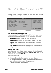
To set a supervisor password, the other security settings. Select the Change User Password item and press . 2. again to selected fields, such as Date and Time. User Access Level (Full Access] This item allows you set a password, this item to set or change password. Change User Password Select this item shows I n s t a l l e d. ... screen shows the default N o t I n s t a l l e d. L i m i t e d allows changes only to disabled password. V i e w O n l y allows access but does not allow you can clear it by erasing the CMOS Real Time Clock (RTC) RAM.
To set a supervisor password, the other security settings. Select the Change User Password item and press . 2. again to selected fields, such as Date and Time. User Access Level (Full Access] This item allows you set a password, this item to set or change password. Change User Password Select this item shows I n s t a l l e d. ... screen shows the default N o t I n s t a l l e d. L i m i t e d allows changes only to disabled password. V i e w O n l y allows access but does not allow you can clear it by erasing the CMOS Real Time Clock (RTC) RAM.

User Guide
Page 100
... you press , a confirmation window appears. Load Setup Defaults This option allows you to save changes and exit. Select E x i t & S a v e C h a n g e s or make other than System Date, System Time, and Password, the BIOS asks for each of the parameters on even when the PC is turned off. Exit & Discard Changes Select this option only...
... you press , a confirmation window appears. Load Setup Defaults This option allows you to save changes and exit. Select E x i t & S a v e C h a n g e s or make other than System Date, System Time, and Password, the BIOS asks for each of the parameters on even when the PC is turned off. Exit & Discard Changes Select this option only...