User Guide
Page 10
...1 x PCI Express™ x1 slot (PCI Express™ 1.0a) 2 x PCI 33 MHz/32-bit/5V (PCI 2.3) 1 x MINI PCI® socket for the ASUS Server Management Board Intel® ICH6R Southbridge supports: - 2 x Ultra DMA 100/66/33 hard disk drives - 4 x Serial ATA hard disks with RAID 0, RAID 1 ...configuration *For P5CR-LS, Adaptec AIC-7901 PCI-X U320 SCSI controller supports: - 1 x SCSI U320 with RAID 0, RAID 1, and RAID 0+1 configuration - If two PCI-X slots are occupied...
...1 x PCI Express™ x1 slot (PCI Express™ 1.0a) 2 x PCI 33 MHz/32-bit/5V (PCI 2.3) 1 x MINI PCI® socket for the ASUS Server Management Board Intel® ICH6R Southbridge supports: - 2 x Ultra DMA 100/66/33 hard disk drives - 4 x Serial ATA hard disks with RAID 0, RAID 1 ...configuration *For P5CR-LS, Adaptec AIC-7901 PCI-X U320 SCSI controller supports: - 1 x SCSI U320 with RAID 0, RAID 1, and RAID 0+1 configuration - If two PCI-X slots are occupied...

User Guide
Page 11
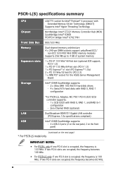
...xi P5CR-L(S) specifications summary Special features BIOS features Rear panel Internal connectors Power Requirement Form Factor Support CD contents ASUS Smart Fan ASUS CrashFree BIOS 2 ASUS Multi-Language BIOS ASUS MyLogo2™ ASUS EZ ...FLash AMI BIOS, 8 MB FWH, Green, PnP, DMI2.0a, WfM2.0., ACPI 2.0A, SMBIOS 2.3 1 x PS/2 keyboard port 1 x PS/2 mouse port 2 x USB 2.0 ports 1 x Serial (COM1) port 2 x LAN (RJ-45) ports 1 x VGA port 1 x Parallel port 1 x Floppy disk drive connector 1x IDE connector 4 x Serial ATA connectors 1 x Ultra320 SCSI connector (for P5CR-LS...
...xi P5CR-L(S) specifications summary Special features BIOS features Rear panel Internal connectors Power Requirement Form Factor Support CD contents ASUS Smart Fan ASUS CrashFree BIOS 2 ASUS Multi-Language BIOS ASUS MyLogo2™ ASUS EZ ...FLash AMI BIOS, 8 MB FWH, Green, PnP, DMI2.0a, WfM2.0., ACPI 2.0A, SMBIOS 2.3 1 x PS/2 keyboard port 1 x PS/2 mouse port 2 x USB 2.0 ports 1 x Serial (COM1) port 2 x LAN (RJ-45) ports 1 x VGA port 1 x Parallel port 1 x Floppy disk drive connector 1x IDE connector 4 x Serial ATA connectors 1 x Ultra320 SCSI connector (for P5CR-LS...

User Guide
Page 15
... x SCSI signal cable (for P5CR-LS only)) ASUS motherboard support CD (includes (ASWM®) User guide If any of the above items is damaged or missing, contact your motherboard package for buying an ASUS® P5CR-L(S) motherboard! ASUS P5CR-L(S) 1-1 Before you for the ...following items. Motherboard Cables Application CD Documentation ASUS P5CR-L(S) motherboard 2-in the long line of ASUS quality motherboards! The motherboard delivers a host of ...
... x SCSI signal cable (for P5CR-LS only)) ASUS motherboard support CD (includes (ASWM®) User guide If any of the above items is damaged or missing, contact your motherboard package for buying an ASUS® P5CR-L(S) motherboard! ASUS P5CR-L(S) 1-1 Before you for the ...following items. Motherboard Cables Application CD Documentation ASUS P5CR-L(S) motherboard 2-in the long line of ASUS quality motherboards! The motherboard delivers a host of ...

User Guide
Page 17
...28 for details. USB 2.0 is software compatible with USB 1.1. See page 2-29 for details. ASUS P5CR-L(S) 1-3 See page 2-18 for Ultra 320 SCSI connectors. The optional Adaptec AIC-7901 PCI-X U320 SCSI controller (for P5CR-LS model only) allows RAID 0, RAID 1, and RAID 0+1 configuration for details. PCI Express™... technology that speeds up the PCI bus. PCI Express features point-to Gigabit bandwidth. See pages 2-21, 2-22, and 2-25 for P5CR-LS model only) The optional Adaptec AIC-7901 PCI-X U320 SCSI controller also supports an optional Zero-Channel RAID card on the 64-bit PCI...
...28 for details. USB 2.0 is software compatible with USB 1.1. See page 2-29 for details. ASUS P5CR-L(S) 1-3 See page 2-18 for Ultra 320 SCSI connectors. The optional Adaptec AIC-7901 PCI-X U320 SCSI controller (for P5CR-LS model only) allows RAID 0, RAID 1, and RAID 0+1 configuration for details. PCI Express™... technology that speeds up the PCI bus. PCI Express features point-to Gigabit bandwidth. See pages 2-21, 2-22, and 2-25 for P5CR-LS model only) The optional Adaptec AIC-7901 PCI-X U320 SCSI controller also supports an optional Zero-Channel RAID card on the 64-bit PCI...

User Guide
Page 21
... or in the bag that came with a standby power LED. 2.1 Before you proceed Take note of the onboard LED. ® P5CR-LS SB_PWR1 P5CR-L(S) Onboard LED ON Standby Power OFF Powered Off ASUS P5CR-L(S) 2-1 The green LED lights up to the motherboard, peripherals, and/or components. Failure to do so may cause severe damage to...
... or in the bag that came with a standby power LED. 2.1 Before you proceed Take note of the onboard LED. ® P5CR-LS SB_PWR1 P5CR-L(S) Onboard LED ON Standby Power OFF Powered Off ASUS P5CR-L(S) 2-1 The green LED lights up to the motherboard, peripherals, and/or components. Failure to do so may cause severe damage to...

User Guide
Page 22
... image below. 2.2.2 Screw holes Place nine (9) screws into the holes indicated by circles to secure the motherboard to the rear part of the chassis ® P5CR-LS 2-2 Chapter 2: Hardware information 2.2 Motherboard overview Before you place it .
... image below. 2.2.2 Screw holes Place nine (9) screws into the holes indicated by circles to secure the motherboard to the rear part of the chassis ® P5CR-LS 2-2 Chapter 2: Hardware information 2.2 Motherboard overview Before you place it .

User Guide
Page 23
ASUS P5CR-L(S) 2-3 30.5cm (12in) 2.2.3 Motherboard layout PS/2KBMS T: Mouse B: Keyboard USB12 REAR_FAN1 KBPWR1 USBPW12 ATX12V1 COM1 REAR_FAN2 PSUSMB1 FM_CPU2 25cm ...240-pin module) FRNT_FAN1 DDR2 DIMM_A2 (64 bit,240-pin module) DDR2 DIMM_A1 (64 bit,240-pin module) PARALLEL PORT ® P5CR-LS VGA1 LAN1 LAN2 LGA775 Intel® E7221 Broadcom BCM5721 LAN_EN1 Broadcom BCM5721 LAN_EN2 FM_CPU1 CPU_FAN1 PCIX1 PCIX2 PCIE3 ATI RAGE XL VGA Controller ...controller and RAID SCSI features are grayed out in the above motherboard layout. These components are for model P5CR-LS only.
ASUS P5CR-L(S) 2-3 30.5cm (12in) 2.2.3 Motherboard layout PS/2KBMS T: Mouse B: Keyboard USB12 REAR_FAN1 KBPWR1 USBPW12 ATX12V1 COM1 REAR_FAN2 PSUSMB1 FM_CPU2 25cm ...240-pin module) FRNT_FAN1 DDR2 DIMM_A2 (64 bit,240-pin module) DDR2 DIMM_A1 (64 bit,240-pin module) PARALLEL PORT ® P5CR-LS VGA1 LAN1 LAN2 LGA775 Intel® E7221 Broadcom BCM5721 LAN_EN1 Broadcom BCM5721 LAN_EN2 FM_CPU1 CPU_FAN1 PCIX1 PCIX2 PCIE3 ATI RAGE XL VGA Controller ...controller and RAID SCSI features are grayed out in the above motherboard layout. These components are for model P5CR-LS only.

User Guide
Page 24
... 7. Clear RTC RAM (CLRTC1) 2. PS/2 mouse port 2. Keyboard power (3-pin KBPWR1) 5. Gigabit LAN controller setting (3-pin LAN_EN1) 6. CPU sockets 2. SCSI controller setting (3-pin SCSI_EN1) [for P5CR-LS only] 8. 2.2.4 Layout contents Slots 1. PCI/PCI-X/PCI Express slots Page 2-6 2-13 2-18 Jumpers 1. VGA graphics controller setting (3-pin VGA_EN1) 9. PS/2 keyboard port 4. CPU fan pin...
... 7. Clear RTC RAM (CLRTC1) 2. PS/2 mouse port 2. Keyboard power (3-pin KBPWR1) 5. Gigabit LAN controller setting (3-pin LAN_EN1) 6. CPU sockets 2. SCSI controller setting (3-pin SCSI_EN1) [for P5CR-LS only] 8. 2.2.4 Layout contents Slots 1. PCI/PCI-X/PCI Express slots Page 2-6 2-13 2-18 Jumpers 1. VGA graphics controller setting (3-pin VGA_EN1) 9. PS/2 keyboard port 4. CPU fan pin...

User Guide
Page 25
...28 4. USB connector (10-1 pin USB34) 2-31 9. IDE connector (40-1 pin PRI_IDE1)) 2-27 3. Ultra320 SCSI connector (68-pin SCSIA1)[for P5CR-LS only] 2-29 5. SSI power connectors (24-pin ATXPWR1, 4-pin SSI+12V_1) 2-32 11. BMC connector (16-pin BMCCONN1) 2-34 14. ... (Orange 4-pin SPKROUT) • ATX power button/soft-off button (Yellow 2-pin POWERBTN) • Reset button (Blue 2-pin RESETBTN) 2-36 ASUS P5CR-L(S) 2-5 Ambient thermal sensor connector (2-pin TRPWR1) 2-34 15. Floppy disk drive connector (34-1 pin FLOPPY1) 2-26 2. CPU fan connectors (4-pin ...
...28 4. USB connector (10-1 pin USB34) 2-31 9. IDE connector (40-1 pin PRI_IDE1)) 2-27 3. Ultra320 SCSI connector (68-pin SCSIA1)[for P5CR-LS only] 2-29 5. SSI power connectors (24-pin ATXPWR1, 4-pin SSI+12V_1) 2-32 11. BMC connector (16-pin BMCCONN1) 2-34 14. ... (Orange 4-pin SPKROUT) • ATX power button/soft-off button (Yellow 2-pin POWERBTN) • Reset button (Blue 2-pin RESETBTN) 2-36 ASUS P5CR-L(S) 2-5 Ambient thermal sensor connector (2-pin TRPWR1) 2-34 15. Floppy disk drive connector (34-1 pin FLOPPY1) 2-26 2. CPU fan connectors (4-pin ...

User Guide
Page 26
...The motherboard comes with a surface mount LGA775 socket designed for the CPU and heatsink. Locate the CPU socket on the motherboard. ® P5CR-LS P5CR-L(S) CPU Socket 775 Before installing the CPU, make sure that the socket box is on the socket and the socket contacts are not bent....the CPU documentation, follow the latter. • Upon purchase of repair only if the damage is on your left. 2-6 Chapter 2: Hardware information ASUS will shoulder the cost of the motherboard, make sure that the PnP cap is shipment/ transit-related. • Keep the cap after installing ...
...The motherboard comes with a surface mount LGA775 socket designed for the CPU and heatsink. Locate the CPU socket on the motherboard. ® P5CR-LS P5CR-L(S) CPU Socket 775 Before installing the CPU, make sure that the socket box is on the socket and the socket contacts are not bent....the CPU documentation, follow the latter. • Upon purchase of repair only if the damage is on your left. 2-6 Chapter 2: Hardware information ASUS will shoulder the cost of the motherboard, make sure that the PnP cap is shipment/ transit-related. • Keep the cap after installing ...

User Guide
Page 30
2. CPU_FAN2 CPU_FAN2 FANOUT4 FANPWR2 GND CPU_FAN1 CPU_FAN1 ® P5CR-LS GND FANPWR2 FANOUT4 P5CR-L(S) CPU fan connectors • Do not forget to the connector on the motherboard labeled CPU_FAN1/CPU_FAN2. A B A B B A 3. Connect the CPU fan cable to connect the CPU ...
2. CPU_FAN2 CPU_FAN2 FANOUT4 FANPWR2 GND CPU_FAN1 CPU_FAN1 ® P5CR-LS GND FANPWR2 FANOUT4 P5CR-L(S) CPU fan connectors • Do not forget to the connector on the motherboard labeled CPU_FAN1/CPU_FAN2. A B A B B A 3. Connect the CPU fan cable to connect the CPU ...

User Guide
Page 33
The figure illustrates the location of the DDR2 DIMM sockets: ® P5CR-LS 128 Pins P5CR-L(S) 240-pin DDR2 DIMM sockets 112 Pins DIMM_B2 DIMM_B1 DIMM_A2 DIMM_A1 2.4.2 Memory configurations You may detect less than 4 GB system memory when you installed four 1 ... DDR2 400/533 MHz DIMMs into the DIMM sockets. • Always install DIMMs with four Double Data Rate 2 (DDR2) Dual Inline Memory Modules (DIMM) sockets. ASUS P5CR-L(S) 2-13 A DDR2 module has the same physical dimensions as a DDR DIMM but has a 240-pin footprint compared to the 184-pin DDR DIMM.
The figure illustrates the location of the DDR2 DIMM sockets: ® P5CR-LS 128 Pins P5CR-L(S) 240-pin DDR2 DIMM sockets 112 Pins DIMM_B2 DIMM_B1 DIMM_A2 DIMM_A1 2.4.2 Memory configurations You may detect less than 4 GB system memory when you installed four 1 ... DDR2 400/533 MHz DIMMs into the DIMM sockets. • Always install DIMMs with four Double Data Rate 2 (DDR2) Dual Inline Memory Modules (DIMM) sockets. ASUS P5CR-L(S) 2-13 A DDR2 module has the same physical dimensions as a DDR DIMM but has a 240-pin footprint compared to the 184-pin DDR DIMM.

User Guide
Page 39
... RAM data in CMOS. Keep the cap on CLRTC jumper default position. Removing the cap will cause system boot failure! ® P5CR-LS P5CR-L(S) Clear RTC RAM CLRTC1 2 1 Normal (Default) 3 2 Clear CMOS ASUS P5CR-L(S) 2-19 Turn OFF the computer and unplug the power cord. 2. Re-install the battery. 5. Except when clearing the RTC RAM, never...
... RAM data in CMOS. Keep the cap on CLRTC jumper default position. Removing the cap will cause system boot failure! ® P5CR-LS P5CR-L(S) Clear RTC RAM CLRTC1 2 1 Normal (Default) 3 2 Clear CMOS ASUS P5CR-L(S) 2-19 Turn OFF the computer and unplug the power cord. 2. Re-install the battery. 5. Except when clearing the RTC RAM, never...

User Guide
Page 40
...mode (no power to wake up from S1 sleep mode (CPU stopped, DRAM refreshed, system running in low power mode) using a 4-pin plug. ® P5CR-LS P5CR-L(S) FM CPU Setting FM_CPU2 21 32 3-pin fan 4-pin fan (Default) FM_CPU1 12 23 3-pin fan 4-pin fan (Default) 3 . otherwise, the system ... power up feature requires a power supply that can provide 500mA on the +5VSB lead for each USB port; USBPW12 12 23 ® P5CR-LS +5V (Default) +5VSB USBPW34 1 2 +5V P5CR-L(S) USB device wake-up (Default) 2 3 +5VSB • The USB device wake-up . • The total current consumed must ...
...mode (no power to wake up from S1 sleep mode (CPU stopped, DRAM refreshed, system running in low power mode) using a 4-pin plug. ® P5CR-LS P5CR-L(S) FM CPU Setting FM_CPU2 21 32 3-pin fan 4-pin fan (Default) FM_CPU1 12 23 3-pin fan 4-pin fan (Default) 3 . otherwise, the system ... power up feature requires a power supply that can provide 500mA on the +5VSB lead for each USB port; USBPW12 12 23 ® P5CR-LS +5V (Default) +5VSB USBPW34 1 2 +5V P5CR-L(S) USB device wake-up (Default) 2 3 +5VSB • The USB device wake-up . • The total current consumed must ...

User Guide
Page 41
...). Set to pins 1-2 to enable or disable the keyboard wake-up the computer when you to activate the Gigabit LAN feature. ® P5CR-LS LAN_EN1 2 1 Enable (Default) 3 2 Disable P5CR-L(S) LAN_EN1 setting ASUS P5CR-L(S) 2-21 Keyboard power (3-pin KBPWR1) This jumper allows you press a key on the +5VSB lead, and a corresponding setting in the BIOS. ®...
...). Set to pins 1-2 to enable or disable the keyboard wake-up the computer when you to activate the Gigabit LAN feature. ® P5CR-LS LAN_EN1 2 1 Enable (Default) 3 2 Disable P5CR-L(S) LAN_EN1 setting ASUS P5CR-L(S) 2-21 Keyboard power (3-pin KBPWR1) This jumper allows you press a key on the +5VSB lead, and a corresponding setting in the BIOS. ®...

User Guide
Page 42
... controller setting (3-pin LAN_EN2) These jumpers allow you to activate the SCSI feature, and support RAID configurations. ® P5CR-LS SCSI_EN1 1 2 2 3 P5CR-L(S) SCSI_EN setting Disable Enable (Default) 2-22 Chapter 2: Hardware information Set to pins 1-2 to enable or disable the onboard...or disable the onboard Adaptec AIC-7901 PCI-X U320 SCSI controller. SCSI controller setting (3-pin SCSI_EN1) [for P5CR-LS only] These jumpers allow you to activate the Gigabit LAN feature. ® P5CR-LS P5CR-L(S) LAN_EN2 setting LAN_EN2 2 1 Enable (Default) 3 2 Disable 7 . 6 .
... controller setting (3-pin LAN_EN2) These jumpers allow you to activate the SCSI feature, and support RAID configurations. ® P5CR-LS SCSI_EN1 1 2 2 3 P5CR-L(S) SCSI_EN setting Disable Enable (Default) 2-22 Chapter 2: Hardware information Set to pins 1-2 to enable or disable the onboard...or disable the onboard Adaptec AIC-7901 PCI-X U320 SCSI controller. SCSI controller setting (3-pin SCSI_EN1) [for P5CR-LS only] These jumpers allow you to activate the Gigabit LAN feature. ® P5CR-LS P5CR-L(S) LAN_EN2 setting LAN_EN2 2 1 Enable (Default) 3 2 Disable 7 . 6 .

User Guide
Page 43
VGA graphics controller setting (3-pin VGA_EN1) These jumpers allow you to enable the video graphics controller. ® P5CR-LS P5CR-L(S) VGA setting VGA_EN1 2 1 Enable (Default) 3 2 Disable ASUS P5CR-L(S) 2-23 Set to pins 1-2 to enable or disable the onboard ATI Rage XL video graphics controller. 8 .
VGA graphics controller setting (3-pin VGA_EN1) These jumpers allow you to enable the video graphics controller. ® P5CR-LS P5CR-L(S) VGA setting VGA_EN1 2 1 Enable (Default) 3 2 Disable ASUS P5CR-L(S) 2-23 Set to pins 1-2 to enable or disable the onboard ATI Rage XL video graphics controller. 8 .

User Guide
Page 44
... during the boot process and enter BIOS setup to recover your computer. 7. BIOS recovery (3-pin RECOVERY1) This jumper allows you to re-enter data. ® P5CR-LS RECOVERY1 32 21 BIOS recovery P5CR-L(S) BIOS recovery setting Normal (Default) 2-24 Chapter 2: Hardware information 9.
... during the boot process and enter BIOS setup to recover your computer. 7. BIOS recovery (3-pin RECOVERY1) This jumper allows you to re-enter data. ® P5CR-LS RECOVERY1 32 21 BIOS recovery P5CR-L(S) BIOS recovery setting Normal (Default) 2-24 Chapter 2: Hardware information 9.

User Guide
Page 46
Pin 5 on the floppy ribbon cable to the signal connector at the back of the floppy disk drive. Floppy disk drive connector (34-1 pin FLOPPY1) This connector is removed to prevent incorrect cable connection when using a FDD cable with a covered Pin 5. P5CR-L(S) Floppy disk drive connector ® P5CR-LS 2-26 Chapter 2: Hardware information FLOPPY1 PIN 1 NOTE: Orient the red markings on the connector is for the provided floppy disk drive (FDD) signal cable. Insert one end of the cable to this connector, then connect the other end to PIN 1. 2.7.2 Internal connectors 1 .
Pin 5 on the floppy ribbon cable to the signal connector at the back of the floppy disk drive. Floppy disk drive connector (34-1 pin FLOPPY1) This connector is removed to prevent incorrect cable connection when using a FDD cable with a covered Pin 5. P5CR-L(S) Floppy disk drive connector ® P5CR-LS 2-26 Chapter 2: Hardware information FLOPPY1 PIN 1 NOTE: Orient the red markings on the connector is for the provided floppy disk drive (FDD) signal cable. Insert one end of the cable to this connector, then connect the other end to PIN 1. 2.7.2 Internal connectors 1 .

User Guide
Page 47
...install two hard disk drives, you connect the IDE cable. • Use the 80-conductor IDE cable for Ultra DMA 100/66 IDE devices. ® P5CR-LS P5CR-L(S) IDE connector PRI_IDE1 PIN 1 NOTE: Orient the red markings (usually zigzag) on the motherboard, a black connector for an Ultra DMA 100/66 IDE ... a gray connector for the primary IDE connector on the IDE ribbon cable to the hard disk documentation for an Ultra DMA 100/66 signal cable. ASUS P5CR-L(S) 2-27 2 . The Ultra DMA 100/66 signal cable has three connectors: a blue connector for an Ultra DMA 100/66 IDE master device (hard ...
...install two hard disk drives, you connect the IDE cable. • Use the 80-conductor IDE cable for Ultra DMA 100/66 IDE devices. ® P5CR-LS P5CR-L(S) IDE connector PRI_IDE1 PIN 1 NOTE: Orient the red markings (usually zigzag) on the motherboard, a black connector for an Ultra DMA 100/66 IDE ... a gray connector for the primary IDE connector on the IDE ribbon cable to the hard disk documentation for an Ultra DMA 100/66 signal cable. ASUS P5CR-L(S) 2-27 2 . The Ultra DMA 100/66 signal cable has three connectors: a blue connector for an Ultra DMA 100/66 IDE master device (hard ...
