
P5A User Manual
Page 4
...Features Setup 45 Details of Chipset Features Setup 46 Power Management Setup 49 Details of the ASUS P5A Motherboard 11 III. INSTALLATION 12 ASUS P5A Motherboard Layout 12 Installation Steps 14 1. Expansion Cards 23 Expansion Card Installation Procedure 23 ...35 Support Software 36 Flash Memory Writer Utility 36 IV. INTRODUCTION 7 How this Manual is Organized 7 Item Checklist 7 II. Central Processing Unit (CPU 21 4. System Memory (DIMM 19 DIMM Memory Installation Procedures 20 3. FEATURES 8 ASUS P5A Motherboard 8 Introduction to ASUS Smart Series Motherboards 9 ...
...Features Setup 45 Details of Chipset Features Setup 46 Power Management Setup 49 Details of the ASUS P5A Motherboard 11 III. INSTALLATION 12 ASUS P5A Motherboard Layout 12 Installation Steps 14 1. Expansion Cards 23 Expansion Card Installation Procedure 23 ...35 Support Software 36 Flash Memory Writer Utility 36 IV. INTRODUCTION 7 How this Manual is Organized 7 Item Checklist 7 II. Central Processing Unit (CPU 21 4. System Memory (DIMM 19 DIMM Memory Installation Procedures 20 3. FEATURES 8 ASUS P5A Motherboard 8 Introduction to ASUS Smart Series Motherboards 9 ...

P5A User Manual
Page 8
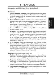
.... • Enhanced ACPI and Anti-Boot Virus BIOS: Features a programmable BIOS, offering enhanced ACPI for virtually automatic setup. • PC100 Memory Support: Equipped with three DIMM sockets to support Intel PC100compliant SDRAMs (8, 16, 32, 64, 128, or 256MB) up . • Wake...meet the enhanced 95MHz/100MHz bus speed requirement. • AGP Slot: Supports AGP cards for a standard individual infrared cable set. 8 ASUS P5A User's Manual A second IrDA connector is available for high performance, component level interconnection targeted at 3D graphical display applications. • PCI...
.... • Enhanced ACPI and Anti-Boot Virus BIOS: Features a programmable BIOS, offering enhanced ACPI for virtually automatic setup. • PC100 Memory Support: Equipped with three DIMM sockets to support Intel PC100compliant SDRAMs (8, 16, 32, 64, 128, or 256MB) up . • Wake...meet the enhanced 95MHz/100MHz bus speed requirement. • AGP Slot: Supports AGP cards for a standard individual infrared cable set. 8 ASUS P5A User's Manual A second IrDA connector is available for high performance, component level interconnection targeted at 3D graphical display applications. • PCI...
P5A User Manual
Page 9
... Support for Plug and Play compatibility and power management for the future operating systems (OS) supporting OS Direct Power Management (OSPM) functionality. ASUS P5A User's Manual 9 The new PC'98 requirements for systems and components are monitored for Windows 95/Windows 98 and Windows NT. With these... no need to upgrade current hard drives or cables. • Concurrent PCI: Concurrent PCI allows multiple PCI transfers from PCI master buses to memory to CPU. • ACPI Ready: ACPI (Advanced Configuration and Power Interface) is operating at a safe heat level to avoid any failures...
... Support for Plug and Play compatibility and power management for the future operating systems (OS) supporting OS Direct Power Management (OSPM) functionality. ASUS P5A User's Manual 9 The new PC'98 requirements for systems and components are monitored for Windows 95/Windows 98 and Windows NT. With these... no need to upgrade current hard drives or cables. • Concurrent PCI: Concurrent PCI allows multiple PCI transfers from PCI master buses to memory to CPU. • ACPI Ready: ACPI (Advanced Configuration and Power Interface) is operating at a safe heat level to avoid any failures...

P5A User Manual
Page 10
... current to present enormous user interfaces and run large applications. II. FEATURES • Voltage Monitoring and Alert: System voltage levels are more critical for more memory and hard drive space to critical motherboard components. Through the way a particular LED illuminates, the user can access vital information from their limited resources more... Down: When CPU fans or system fans malfunction, the system will warn the user before the system resources are used up to the user. 10 ASUS P5A User's Manual
... current to present enormous user interfaces and run large applications. II. FEATURES • Voltage Monitoring and Alert: System voltage levels are more critical for more memory and hard drive space to critical motherboard components. Through the way a particular LED illuminates, the user can access vital information from their limited resources more... Down: When CPU fans or system fans malfunction, the system will warn the user before the system resources are used up to the user. 10 ASUS P5A User's Manual
P5A User Manual
Page 13
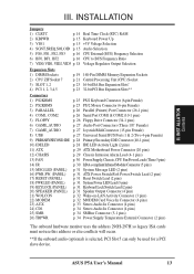
ASUS P5A User's Manual 13 III. INST ALLATION Contents III. INSTALLATION Jumpers 1) CLRTC p. 14 Real Time Clock (RTC) RAM 2) KBPWR p. 15 Keyboard Power Up 3) VIO1 p. 15 +3V ... BUS Frequency Ratio 7) VID0, VID1, VID2, VID3 p. 18 Voltage Regulator Output Selection Expansion Slots 1) DIMM Sockets 2) CPU ZIF Socket 7 3) SLOT 1, 2 4) PCI 1, 2, 3,4,5 p. 19 168-Pin DIMM Memory Expansion Sockets p. 21 Central Processing Unit (CPU) Socket p. 23 16-bit ISA Bus Expansion Slots* p. 23 32-bit PCI Bus Expansion Slots** Connectors 1) PS2KBMS p. 25...
ASUS P5A User's Manual 13 III. INST ALLATION Contents III. INSTALLATION Jumpers 1) CLRTC p. 14 Real Time Clock (RTC) RAM 2) KBPWR p. 15 Keyboard Power Up 3) VIO1 p. 15 +3V ... BUS Frequency Ratio 7) VID0, VID1, VID2, VID3 p. 18 Voltage Regulator Output Selection Expansion Slots 1) DIMM Sockets 2) CPU ZIF Socket 7 3) SLOT 1, 2 4) PCI 1, 2, 3,4,5 p. 19 168-Pin DIMM Memory Expansion Sockets p. 21 Central Processing Unit (CPU) Socket p. 23 16-bit ISA Bus Expansion Slots* p. 23 32-bit PCI Bus Expansion Slots** Connectors 1) PS2KBMS p. 25...

P5A User Manual
Page 14
Install System Memory Modules 3. Computer motherboards, baseboards and components, such as the power supply case. 3. Use a grounded wrist strap before handling computer..., you work on the inside. 2. Connect Ribbon Cables, Cabinet Wires, and Power Supply 6. Setup the BIOS Software 1. INST ALLATION Jumpers P5A Clear RTC RAM CLRTC Short solder points to touch the IC chips, leads or connectors, or other components. 4. INSTALLATION Installation Steps Before using...(RTC) RAM (CLRTC) The CMOS RAM is powered by the edges and try not to Clear CMOS 14 ASUS P5A User's Manual
Install System Memory Modules 3. Computer motherboards, baseboards and components, such as the power supply case. 3. Use a grounded wrist strap before handling computer..., you work on the inside. 2. Connect Ribbon Cables, Cabinet Wires, and Power Supply 6. Setup the BIOS Software 1. INST ALLATION Jumpers P5A Clear RTC RAM CLRTC Short solder points to touch the IC chips, leads or connectors, or other components. 4. INSTALLATION Installation Steps Before using...(RTC) RAM (CLRTC) The CMOS RAM is powered by the edges and try not to Clear CMOS 14 ASUS P5A User's Manual

P5A User Manual
Page 19
... DIMMs come in BIOS setup. IMPORTANT (see General DIMM Notes below) • To make the proper settings through SDRAM Configuration under these speeds. ASUS P5A User's Manual 19 INST ALLATION System Memory III. One side (with higher pin density than 18 chips are available for 3.3Volt (power level) unbuffered Synchronous Dynamic Random Access...
... DIMMs come in BIOS setup. IMPORTANT (see General DIMM Notes below) • To make the proper settings through SDRAM Configuration under these speeds. ASUS P5A User's Manual 19 INST ALLATION System Memory III. One side (with higher pin density than 18 chips are available for 3.3Volt (power level) unbuffered Synchronous Dynamic Random Access...

P5A User Manual
Page 20
INSTALLATION DIMM Memory Installation Procedures: Insert the module(s) as shown. SDRAM DIMMs have different pin contacts on each side and therefore have the same pin contacts on both ... motherboard. R III. III. INST ALLATION System Memory 88 Pins 60 Pins 20 Pins Lock P5A 168 Pin DIMM Memory Sockets The DIMMs must tell your retailer the correct DIMM type before purchasing. DRAM SIMM modules have a higher pin density. This motherboard supports four clock signals. 20 ASUS P5A User's Manual Because the number of pins...
INSTALLATION DIMM Memory Installation Procedures: Insert the module(s) as shown. SDRAM DIMMs have different pin contacts on each side and therefore have the same pin contacts on both ... motherboard. R III. III. INST ALLATION System Memory 88 Pins 60 Pins 20 Pins Lock P5A 168 Pin DIMM Memory Sockets The DIMMs must tell your retailer the correct DIMM type before purchasing. DRAM SIMM modules have a higher pin density. This motherboard supports four clock signals. 20 ASUS P5A User's Manual Because the number of pins...

P5A User Manual
Page 24
...card, you can select a DMA channel in it that the jumpers on this address or else conflicts will occur. P5A Accelerated Graphics Port (AGP) 24 ASUS P5A User's Manual INSTALLATION To simplify this process, this motherboard are assigned automatically from those available. Assigning DMA Channels for...requires an IRQ. DMA assignments for an ISA Configuration Utility. The PCI and PNP configuration of graphics cards with ultra-high memory bandwidth, such as the IRQ assignment process described earlier. Since all the PCI slots on your vendor for this motherboard complies ...
...card, you can select a DMA channel in it that the jumpers on this address or else conflicts will occur. P5A Accelerated Graphics Port (AGP) 24 ASUS P5A User's Manual INSTALLATION To simplify this process, this motherboard are assigned automatically from those available. Assigning DMA Channels for...requires an IRQ. DMA assignments for an ISA Configuration Utility. The PCI and PNP configuration of graphics cards with ultra-high memory bandwidth, such as the IRQ assignment process described earlier. Since all the PCI slots on your vendor for this motherboard complies ...
P5A User Manual
Page 36
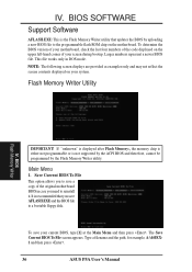
...Save Current BIOS To File This option allows you to reinstall it. IV. To determine the BIOS version of your screen during bootup. Flash Memory Writer Utility IV. The Save Current BIOS To File screen appears. NOTE: The following screen displays are provided as examples only and may not ... BIOS by the Flash Memory Writer utility. To save AFLASH.EXE and the BIOS file to the programmable flash ROM chip on your current BIOS, type [1] at the Main Menu and then press . Type a filename and the path, for example, A:\440XX1 and then press . 36 ASUS P5A User's Manual Larger numbers...
...Save Current BIOS To File This option allows you to reinstall it. IV. To determine the BIOS version of your screen during bootup. Flash Memory Writer Utility IV. The Save Current BIOS To File screen appears. NOTE: The following screen displays are provided as examples only and may not ... BIOS by the Flash Memory Writer utility. To save AFLASH.EXE and the BIOS file to the programmable flash ROM chip on your current BIOS, type [1] at the Main Menu and then press . Type a filename and the path, for example, A:\440XX1 and then press . 36 ASUS P5A User's Manual Larger numbers...

P5A User Manual
Page 37
... file. Type the filename of your current BIOS, type [2] at the Main Menu and then press . The utility starts to start the update. BIOS Flash Memory Writer ASUS P5A User's Manual 37 BIOS SOFTWARE 2. When prompted to confirm the BIOS update, press Y to program the new BIOS information into the flash ROM. Update...
... file. Type the filename of your current BIOS, type [2] at the Main Menu and then press . The utility starts to start the update. BIOS Flash Memory Writer ASUS P5A User's Manual 37 BIOS SOFTWARE 2. When prompted to confirm the BIOS update, press Y to program the new BIOS information into the flash ROM. Update...

P5A User Manual
Page 38
...floppy disk by typing [FORMAT A:/S] from the Internet (WWW or FTP) or a BBS (Bulletin Board Service) (see ASUS CONTACT INFORMATION on the previous page for details) and save to File. Save Current BIOS To File on page 3 for ... prompt, type AFLASH and then press . 4. At the Main Menu, type 2 and then press . If the Flash Memory Writer utility was not able to successfully update a complete BIOS file, your system from the disk you saved to disk above... Updating Your Motherboard's BIOS Upon First Use of the Computer System 1. BIOS Flash Memory Writer 38 ASUS P5A User's Manual
...floppy disk by typing [FORMAT A:/S] from the Internet (WWW or FTP) or a BBS (Bulletin Board Service) (see ASUS CONTACT INFORMATION on the previous page for details) and save to File. Save Current BIOS To File on page 3 for ... prompt, type AFLASH and then press . 4. At the Main Menu, type 2 and then press . If the Flash Memory Writer utility was not able to successfully update a complete BIOS file, your system from the disk you saved to disk above... Updating Your Motherboard's BIOS Upon First Use of the Computer System 1. BIOS Flash Memory Writer 38 ASUS P5A User's Manual

P5A User Manual
Page 39
... are a little bit late pressing the mentioned key(s), POST will continue with the opportunity to enter new setup information. BIOS SOFTWARE 6. Use the Flash Memory Writer utility to call Setup, reset the system by pressing + + , or by turning the system off and then back on the system case. ...This section describes how to call up Setup. This appears during the Power-On Self Test (POST). BIOS BIOS Setup ASUS P5A User's Manual 39 The BIOS ROM of these memory chips can also restart by pressing the Reset button on again. If you are released. But do so only if the...
... are a little bit late pressing the mentioned key(s), POST will continue with the opportunity to enter new setup information. BIOS SOFTWARE 6. Use the Flash Memory Writer utility to call Setup, reset the system by pressing + + , or by turning the system off and then back on the system case. ...This section describes how to call up Setup. This appears during the Power-On Self Test (POST). BIOS BIOS Setup ASUS P5A User's Manual 39 The BIOS ROM of these memory chips can also restart by pressing the Reset button on again. If you are released. But do so only if the...

P5A User Manual
Page 40
... values usually get lost or damaged, or if you change your system hardware configuration, you will then appear to provide you to 2079) 40 ASUS P5A User's Manual Take note of these keys and their respective uses. Valid values for this screen are : Month: (1 to 12), Day: ...hardware configuration and set the current date. If the motherboard is readonly and automatically adjusts accordingly. User-configurable fields appear in the CMOS memory on the selected field, press . IV. Standard CMOS Setup Standard CMOS Setup allows you with a list of this screen. At the...
... values usually get lost or damaged, or if you change your system hardware configuration, you will then appear to provide you to 2079) 40 ASUS P5A User's Manual Take note of these keys and their respective uses. Valid values for this screen are : Month: (1 to 12), Day: ...hardware configuration and set the current date. If the motherboard is readonly and automatically adjusts accordingly. User-configurable fields appear in the CMOS memory on the selected field, press . IV. Standard CMOS Setup Standard CMOS Setup allows you with a list of this screen. At the...
P5A User Manual
Page 44
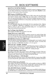
... such as information access is to SCSI. If not detected, IRQ12 will reserve IRQ12 for the PS/2 Mouse. BIOS BIOS Features 44 ASUS P5A User's Manual BIOS SOFTWARE Quick Power On Self Test (Enabled) This field speeds up the Power-On Self Test (POST) routine by... Mouse Function Control (Auto) The setting of Disabled...PCI/VGA Palette Snoop (Disabled) Some display cards that can utilize this on each test. OS/2 Onboard Memory > 64M (Disabled) When using a SCSI hard disk drive. CDROM,C,A; C only; LS/ZIP, C; HDD S.M.A.R.T. and C,A. Floppy Disk Access Control (R/W) ...
... such as information access is to SCSI. If not detected, IRQ12 will reserve IRQ12 for the PS/2 Mouse. BIOS BIOS Features 44 ASUS P5A User's Manual BIOS SOFTWARE Quick Power On Self Test (Enabled) This field speeds up the Power-On Self Test (POST) routine by... Mouse Function Control (Auto) The setting of Disabled...PCI/VGA Palette Snoop (Disabled) Some display cards that can utilize this on each test. OS/2 Onboard Memory > 64M (Disabled) When using a SCSI hard disk drive. CDROM,C,A; C only; LS/ZIP, C; HDD S.M.A.R.T. and C,A. Floppy Disk Access Control (R/W) ...

P5A User Manual
Page 45
... time you start your system. Four delay rate options are noted in parenthesis next to know which the system registers repeated keystrokes. ASUS P5A User's Manual 45 Security Option (System) When you install other settings are the same as in this purpose. The default setting ...20, 24, and 30. Setup default setting is System, where the system prompts for the Supervisor Password. IV. Shadowing a ROM reduces the memory available between 640KB and 1024KB by the amount used for displaying the first and second characters. Typematic Delay (Msec) (250) This field sets ...
... time you start your system. Four delay rate options are noted in parenthesis next to know which the system registers repeated keystrokes. ASUS P5A User's Manual 45 Security Option (System) When you install other settings are the same as in this purpose. The default setting ...20, 24, and 30. Setup default setting is System, where the system prompts for the Supervisor Password. IV. Shadowing a ROM reduces the memory available between 640KB and 1024KB by the amount used for displaying the first and second characters. Typematic Delay (Msec) (250) This field sets ...
P5A User Manual
Page 46
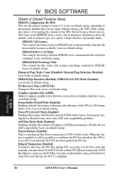
... Leave both on default setting. Graphics Aperture Size (64MB) Memory-mapped, graphics data structures can reside in the SPD (Serial Presence Detect) device. When this feature is a mechanism that are using. BIOS Chipset Features 46 ASUS P5A User's Manual Chipset Features IV. SDRAM RAS Precharge Time This... This controls the latency between SDRAM active command and the read command and the time that normally consume about the module, such as memory type, size, speed, voltage interface, and module banks. Leave on default setting. Leave on default setting. IV. This 8-pin ...
... Leave both on default setting. Graphics Aperture Size (64MB) Memory-mapped, graphics data structures can reside in the SPD (Serial Presence Detect) device. When this feature is a mechanism that are using. BIOS Chipset Features 46 ASUS P5A User's Manual Chipset Features IV. SDRAM RAS Precharge Time This... This controls the latency between SDRAM active command and the read command and the time that normally consume about the module, such as memory type, size, speed, voltage interface, and module banks. Leave on default setting. Leave on default setting. IV. This 8-pin ...
P5A User Manual
Page 47
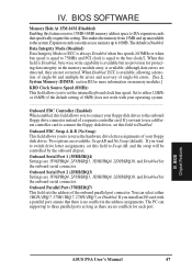
...IRQ10, and Disabled for the onboard serial connector. You can support up to the bus clock/2. BIOS Chipset Features IV. Expansion cards can only access memory up to the onboard floppy drive connector instead of single-bit errors. [See 2. Onboard FDC Swap A & B (No Swap) This field ...to three parallel ports as long as there are no conflict in the memory module array is Disabled. System Memory (DIMM), section III for each port. BIOS Chipset Features ASUS P5A User's Manual 47 This makes the memory from 15MB and up unavailable to set this field to Swap AB, and...
...IRQ10, and Disabled for the onboard serial connector. You can support up to the bus clock/2. BIOS Chipset Features IV. Expansion cards can only access memory up to the onboard floppy drive connector instead of single-bit errors. [See 2. Onboard FDC Swap A & B (No Swap) This field ...to three parallel ports as long as there are no conflict in the memory module array is Disabled. System Memory (DIMM), section III for each port. BIOS Chipset Features ASUS P5A User's Manual 47 This makes the memory from 15MB and up unavailable to set this field to Swap AB, and...
P5A User Manual
Page 53
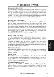
... you install a legacy ISA card that requires a unique DMA channel, and you must support USB function. BIOS ASUS P5A User's Manual 53 If you are not using an ICU, you are using that uses any memory segment within the C800H and DFFFH address range. The default setting is using an ICU to accomplish...
... you install a legacy ISA card that requires a unique DMA channel, and you must support USB function. BIOS ASUS P5A User's Manual 53 If you are not using an ICU, you are using that uses any memory segment within the C800H and DFFFH address range. The default setting is using an ICU to accomplish...
P5A User Manual
Page 57
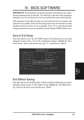
... the CMOS memory all modifications you do not need the data stored on an older previous system, incorrect parameters may be used when the disk was already formatted on the hard disk. You will not be readable. IV. If the parameters listed differ from the Standard CMOS Setup screen. ASUS P5A User's Manual...
... the CMOS memory all modifications you do not need the data stored on an older previous system, incorrect parameters may be used when the disk was already formatted on the hard disk. You will not be readable. IV. If the parameters listed differ from the Standard CMOS Setup screen. ASUS P5A User's Manual...


