P5A User Manual
Page 1
R P5A Pentium® Super7 Motherboard USER'S MANUAL
R P5A Pentium® Super7 Motherboard USER'S MANUAL

P5A User Manual
Page 4
... Unit (CPU 21 4. BIOS SOFTWARE 36 Main Menu 36 Managing and Updating Your Motherboard's BIOS 38 6. FEATURES 8 ASUS P5A Motherboard 8 Introduction to ASUS Smart Series Motherboards 9 Parts of Power Management Setup 49 4 ASUS P5A User's Manual System Memory (DIMM 19 DIMM Memory Installation Procedures 20 3. Expansion Cards...Features Setup 45 Details of Chipset Features Setup 46 Power Management Setup 49 Details of the ASUS P5A Motherboard 11 III. External Connectors 25 Power Connection Procedures 35 Support Software 36 Flash Memory Writer Utility 36 IV. CONTENTS...
... Unit (CPU 21 4. BIOS SOFTWARE 36 Main Menu 36 Managing and Updating Your Motherboard's BIOS 38 6. FEATURES 8 ASUS P5A Motherboard 8 Introduction to ASUS Smart Series Motherboards 9 Parts of Power Management Setup 49 4 ASUS P5A User's Manual System Memory (DIMM 19 DIMM Memory Installation Procedures 20 3. Expansion Cards...Features Setup 45 Details of Chipset Features Setup 46 Power Management Setup 49 Details of the ASUS P5A Motherboard 11 III. External Connectors 25 Power Connection Procedures 35 Support Software 36 Flash Memory Writer Utility 36 IV. CONTENTS...

P5A User Manual
Page 5
... Chassis Sensor 63 Using the ASUS CIDB 63 Setting up the ASUS CIDB 64 ASUS CIDB Additional Considerations 64 VII. ASUS LAN Card 65 ASUS PCI-L101 Fast Ethernet Card 65 Features 66 Software Driver Support 66 Question and Answer 66 APPENDIX 67 Glossary 67 ASUS P5A User's Manual 5 SUPPORT SOFTWARE 59 ASUS Smart Motherboard Support CD 59 Desktop...
... Chassis Sensor 63 Using the ASUS CIDB 63 Setting up the ASUS CIDB 64 ASUS CIDB Additional Considerations 64 VII. ASUS LAN Card 65 ASUS PCI-L101 Fast Ethernet Card 65 Features 66 Software Driver Support 66 Question and Answer 66 APPENDIX 67 Glossary 67 ASUS P5A User's Manual 5 SUPPORT SOFTWARE 59 ASUS Smart Motherboard Support CD 59 Desktop...

P5A User Manual
Page 7
... Support CD with drivers and utilities (1) User's Manual ASUS CIDB chassis sensor module (optional) ASUS IrDA-compliant infrared module (optional) ASUS PCI-L101 Wake-On-LAN 10/100 Ethernet Card (optional) ASUS P5A User's Manual 7 If you discover damaged or missing items...Checklist I . I . Installation Instructions on the included support software VI. ASUS L101 Card Installation of the ASUS LAN card (optional) APPENDIX Glossary of Terms Item Checklist Please check that your retailer. (1) ASUS Motherboard (1) IDE ribbon cable for master and slave drives (1) Ribbon cable for (1)...
... Support CD with drivers and utilities (1) User's Manual ASUS CIDB chassis sensor module (optional) ASUS IrDA-compliant infrared module (optional) ASUS PCI-L101 Wake-On-LAN 10/100 Ethernet Card (optional) ASUS P5A User's Manual 7 If you discover damaged or missing items...Checklist I . I . Installation Instructions on the included support software VI. ASUS L101 Card Installation of the ASUS LAN card (optional) APPENDIX Glossary of Terms Item Checklist Please check that your retailer. (1) ASUS Motherboard (1) IDE ribbon cable for master and slave drives (1) Ribbon cable for (1)...

P5A User Manual
Page 8
.... (Requires DMI-enabled components.) (See section V) • USB, PS/2 Mouse, IrDA Connector: Supports an optional cable and bracket set . 8 ASUS P5A User's Manual Supports Japanese "Floppy 3 mode" (3.5-inch disk drive: 1.2MB) and LS-120 floppy disk drives (3.5-inch disk drive: 120 MB, ...IDE devices in hardware-based virus protection through BIOS, which allows hardware to an unused expansion slot on the system chassis. II. FEATURES ASUS P5A Motherboard • ALi AGPset: ALi® (Acer Laboratories Inc.) Aladdin V AGPset with support for a 100MHz Front Side Bus (FSB), ...
.... (Requires DMI-enabled components.) (See section V) • USB, PS/2 Mouse, IrDA Connector: Supports an optional cable and bracket set . 8 ASUS P5A User's Manual Supports Japanese "Floppy 3 mode" (3.5-inch disk drive: 1.2MB) and LS-120 floppy disk drives (3.5-inch disk drive: 120 MB, ...IDE devices in hardware-based virus protection through BIOS, which allows hardware to an unused expansion slot on the system chassis. II. FEATURES ASUS P5A Motherboard • ALi AGPset: ALi® (Acer Laboratories Inc.) Aladdin V AGPset with support for a 100MHz Front Side Bus (FSB), ...
P5A User Manual
Page 9
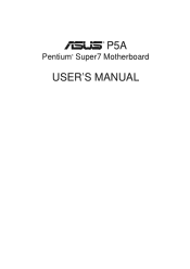
...ready around the clock, yet satisfy all the energy saving standards. FEATURES Introduction to ASUS Smart Series Motherboards Performance • SDRAM Optimized Performance: ASUS Smart Series motherboards support the new generation memory-Synchronous Dynamic Random Access Memory (SDRAM)-which increases the ...Chassis intrusion Detection: Supports chassis-intrusion monitoring through LDCM and the optional ASUS CIDB chassis sensor module. The best of the ASUS Smart Series motherboards meet PC'98 compliancy. II. ASUS P5A User's Manual 9 The new PC'98 requirements for systems and components ...
...ready around the clock, yet satisfy all the energy saving standards. FEATURES Introduction to ASUS Smart Series Motherboards Performance • SDRAM Optimized Performance: ASUS Smart Series motherboards support the new generation memory-Synchronous Dynamic Random Access Memory (SDRAM)-which increases the ...Chassis intrusion Detection: Supports chassis-intrusion monitoring through LDCM and the optional ASUS CIDB chassis sensor module. The best of the ASUS Smart Series motherboards meet PC'98 compliancy. II. ASUS P5A User's Manual 9 The new PC'98 requirements for systems and components ...

P5A User Manual
Page 10
...Series II. FEATURES • Voltage Monitoring and Alert: System voltage levels are monitored to ensure stable current to the user. 10 ASUS P5A User's Manual Through the way a particular LED illuminates, the user can access vital information from their limited resources more efficiently. ...noise, and is necessary to present enormous user interfaces and run large applications. A simple glimpse provides useful information to critical motherboard components. The CPU utilization will restore normal operations when temperature falls below a safe level. • Auto Fan Off: The...
...Series II. FEATURES • Voltage Monitoring and Alert: System voltage levels are monitored to ensure stable current to the user. 10 ASUS P5A User's Manual Through the way a particular LED illuminates, the user can access vital information from their limited resources more efficiently. ...noise, and is necessary to present enormous user interfaces and run large applications. A simple glimpse provides useful information to critical motherboard components. The CPU utilization will restore normal operations when temperature falls below a safe level. • Auto Fan Off: The...

P5A User Manual
Page 11
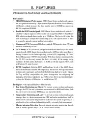
II. FEA TURES Motherboard Parts II. FEATURES Parts of the ASUS P5A Motherboard PS/2 Mouse (top) and Keyboard USB Port ATX Power CPU ZIF ALi Aladdin V Socket 7 AGPset 3 DIMM Sockets Serial and Parallel Connectors 512KB/1MB Pipelined Burst L2 Cache Game/MIDI Port (optional) Accelerated Graphics Port ESS Audio (optional) 5 PCI Slots Health Monitoring Chip (optional) 2 ISA Slots ASUS P5A User's Manual 11
II. FEA TURES Motherboard Parts II. FEATURES Parts of the ASUS P5A Motherboard PS/2 Mouse (top) and Keyboard USB Port ATX Power CPU ZIF ALi Aladdin V Socket 7 AGPset 3 DIMM Sockets Serial and Parallel Connectors 512KB/1MB Pipelined Burst L2 Cache Game/MIDI Port (optional) Accelerated Graphics Port ESS Audio (optional) 5 PCI Slots Health Monitoring Chip (optional) 2 ISA Slots ASUS P5A User's Manual 11
P5A User Manual
Page 12
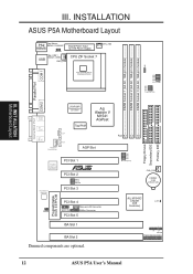
... IDE FS0 FS1 FS2 FS3 BUS Frequency CHA_FAN CR2032 3 Volt Lithium Cell ALi M1543C Chipset (IDE Controller) CLRTC IR + IDELED Panel Connections 12 ASUS P5A User's Manual III. INSTALLATION ASUS P5A Motherboard Layout PS2 Top: Mouse Bottom: Keyboard KBMS KBPWR Board Power Input for ATX Power Supply USB Top: USB 1 Bottom: USB 2 PWR_FAN CPU ZIF...
... IDE FS0 FS1 FS2 FS3 BUS Frequency CHA_FAN CR2032 3 Volt Lithium Cell ALi M1543C Chipset (IDE Controller) CLRTC IR + IDELED Panel Connections 12 ASUS P5A User's Manual III. INSTALLATION ASUS P5A Motherboard Layout PS2 Top: Mouse Bottom: Keyboard KBMS KBPWR Board Power Input for ATX Power Supply USB Top: USB 1 Bottom: USB 2 PWR_FAN CPU ZIF...
P5A User Manual
Page 13
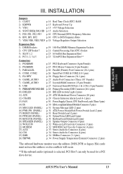
... 1 & 2 (Two 4-pin Female) 9) PRIMARY/SECOND.IDE p. 28 Primary/Secondary IDE Connector (40-1 pins) 10) IDELED p. 28 IDE LED Activity Light (2 pins) 11) ATX p. 29 ATX Motherboard Power Connector (20 pins) 12) CHASIS p. 29 Chassis Intrusion Alarm Lead (4-1 pins) 13) FAN p. 30 Power Supply, Chassis, CPU Fan Power Leads (Three 3 pins) 14... use this address or else conflicts will occur. **If the onboard audio (optional) is selected, PCI Slot 5 can only be used for a PCI slave device. ASUS P5A User's Manual 13 III.
... 1 & 2 (Two 4-pin Female) 9) PRIMARY/SECOND.IDE p. 28 Primary/Secondary IDE Connector (40-1 pins) 10) IDELED p. 28 IDE LED Activity Light (2 pins) 11) ATX p. 29 ATX Motherboard Power Connector (20 pins) 12) CHASIS p. 29 Chassis Intrusion Alarm Lead (4-1 pins) 13) FAN p. 30 Power Supply, Chassis, CPU Fan Power Leads (Three 3 pins) 14... use this address or else conflicts will occur. **If the onboard audio (optional) is selected, PCI Slot 5 can only be used for a PCI slave device. ASUS P5A User's Manual 13 III.

P5A User Manual
Page 14
...the Central Processing Unit (CPU) 4. To protect them against damage from the system. If you must complete the following steps: 1. R III. Computer motherboards, baseboards and components, such as the power supply case. 3. Hold components by the onboard button cell battery. Real Time Clock (RTC) RAM (CLRTC... work on your computer when working on your hands to a safely grounded object or to Clear CMOS 14 ASUS P5A User's Manual Jumpers WARNING! INST ALLATION Jumpers P5A Clear RTC RAM CLRTC Short solder points to a metal object, such as SCSI cards, contain very delicate ...
...the Central Processing Unit (CPU) 4. To protect them against damage from the system. If you must complete the following steps: 1. R III. Computer motherboards, baseboards and components, such as the power supply case. 3. Hold components by the onboard button cell battery. Real Time Clock (RTC) RAM (CLRTC... work on your computer when working on your hands to a safely grounded object or to Clear CMOS 14 ASUS P5A User's Manual Jumpers WARNING! INST ALLATION Jumpers P5A Clear RTC RAM CLRTC Short solder points to a metal object, such as SCSI cards, contain very delicate ...

P5A User Manual
Page 17
ASUS P5A User's Manual 17 Mult.) Mult. INST ALLATION Jumpers III. FS3 FS2 FS1 FS0 BF0 BF1 BF2 AMD-K6-III/450 AMD-K6-III/400 450MHz A-4....-PR166+133MHz E-2.0x 66MHz [2-3] [2-3] [2-3] [1-2] [2-3] [1-2] [----] IDT WinChip 2™ 240MHz F-4.0x 60MHz [2-3] [2-3] [2-3] [2-3] [2-3] [1-2] [2-3] *The only IBM or Cyrix 6x86(L) (or M I) that is supported on this motherboard is revision 2.7 or later (see ASUS CONTACT INFORMATION for URLs). BUS F. INSTALLATION Set the jumpers by the Internal speed of your CPU as follows: CPU Model Freq. (BUS Freq...
ASUS P5A User's Manual 17 Mult.) Mult. INST ALLATION Jumpers III. FS3 FS2 FS1 FS0 BF0 BF1 BF2 AMD-K6-III/450 AMD-K6-III/400 450MHz A-4....-PR166+133MHz E-2.0x 66MHz [2-3] [2-3] [2-3] [1-2] [2-3] [1-2] [----] IDT WinChip 2™ 240MHz F-4.0x 60MHz [2-3] [2-3] [2-3] [2-3] [2-3] [1-2] [2-3] *The only IBM or Cyrix 6x86(L) (or M I) that is supported on this motherboard is revision 2.7 or later (see ASUS CONTACT INFORMATION for URLs). BUS F. INSTALLATION Set the jumpers by the Internal speed of your CPU as follows: CPU Model Freq. (BUS Freq...

P5A User Manual
Page 18
... on this motherboard must be Revision 2.7 or later. The number should read G8DC6620A or later. 7. AMD (.35micron) K6-166,200 ---- INST ALLATION Jumpers VID3 VID2 VID1 VID0 VID3 VID2 VID1 VID0 VID3 VID2 VID1 VID0 VID3 VID2 VID1 VID0 VID3 VID2 VID1 VID0 P5A CPU Core ...5Volts 2.6Volts 1 2 3 3.0Volts 3.1Volts 1 2 3 3.5Volts 2.2Volts 2.7Volts 3.2Volts 2.3Volts 2.8Volts 3.3Volts 2.4Volts 2.9Volts 3.4Volts 18 ASUS P5A User's Manual INSTALLATION Compatible Cyrix CPU Identification The only Cyrix 6x86-PR166+ CPU that is only intended as a simple guideline and thus may not be...
... on this motherboard must be Revision 2.7 or later. The number should read G8DC6620A or later. 7. AMD (.35micron) K6-166,200 ---- INST ALLATION Jumpers VID3 VID2 VID1 VID0 VID3 VID2 VID1 VID0 VID3 VID2 VID1 VID0 VID3 VID2 VID1 VID0 VID3 VID2 VID1 VID0 P5A CPU Core ...5Volts 2.6Volts 1 2 3 3.0Volts 3.1Volts 1 2 3 3.5Volts 2.2Volts 2.7Volts 3.2Volts 2.3Volts 2.8Volts 3.3Volts 2.4Volts 2.9Volts 3.4Volts 18 ASUS P5A User's Manual INSTALLATION Compatible Cyrix CPU Identification The only Cyrix 6x86-PR166+ CPU that is only intended as a simple guideline and thus may not be...

P5A User Manual
Page 19
ASUS P5A User's Manual 19 System Memory (DIMM) This motherboard uses only Dual Inline Memory Modules (DIMMs). To utilize the chipset's Error Checking and Correction (ECC) feature, you must be com- Install memory in...specification.. stability. • SDRAM chips are available for 3.3Volt (power level) unbuffered Synchronous Dynamic Random Access Memory (SDRAM) of choice for system stability. • ASUS motherboards support SPD (Serial Presence Detect) DIMMs. This is recommended through "Chipset Features Setup" in 16, 32, 64,128MB; Memory speed setup is the memory of...
ASUS P5A User's Manual 19 System Memory (DIMM) This motherboard uses only Dual Inline Memory Modules (DIMMs). To utilize the chipset's Error Checking and Correction (ECC) feature, you must be com- Install memory in...specification.. stability. • SDRAM chips are available for 3.3Volt (power level) unbuffered Synchronous Dynamic Random Access Memory (SDRAM) of choice for system stability. • ASUS motherboards support SPD (Serial Presence Detect) DIMMs. This is recommended through "Chipset Features Setup" in 16, 32, 64,128MB; Memory speed setup is the memory of...

P5A User Manual
Page 20
SDRAM DIMMs have a higher pin density. R III. INST ALLATION System Memory 88 Pins 60 Pins 20 Pins Lock P5A 168 Pin DIMM Memory Sockets The DIMMs must tell your retailer the correct DIMM type before purchasing. You must be 3.3Volt unbuffered ...Notch Key Definitions (3.3V) DRAM Key Position RFU Unbuffered Buffered Voltage Key Position 5.0V Reserved 3.3V The notches on the motherboard. This motherboard supports four clock signals. 20 ASUS P5A User's Manual DRAM SIMM modules have the same pin contacts on each side and therefore have different pin contacts on both ...
SDRAM DIMMs have a higher pin density. R III. INST ALLATION System Memory 88 Pins 60 Pins 20 Pins Lock P5A 168 Pin DIMM Memory Sockets The DIMMs must tell your retailer the correct DIMM type before purchasing. You must be 3.3Volt unbuffered ...Notch Key Definitions (3.3V) DRAM Key Position RFU Unbuffered Buffered Voltage Key Position 5.0V Reserved 3.3V The notches on the motherboard. This motherboard supports four clock signals. 20 ASUS P5A User's Manual DRAM SIMM modules have the same pin contacts on each side and therefore have different pin contacts on both ...

P5A User Manual
Page 21
... corner of the CPU with the motherboard should have a CPU fan that is missing from the socket then upwards to a 90-degree right angle. Once completely inserted, hold down on the CPU that corner. Blank 1 Lever Lock R P5A ZIF Socket 7 ASUS P5A User's Manual 21 Insert the CPU... with ZIF Socket 5 processors. Central Processing Unit (CPU) The motherboard provides a 321-pin ZIF Socket 7 that will only fit in the one hole is ...
... corner of the CPU with the motherboard should have a CPU fan that is missing from the socket then upwards to a 90-degree right angle. Once completely inserted, hold down on the CPU that corner. Blank 1 Lever Lock R P5A ZIF Socket 7 ASUS P5A User's Manual 21 Insert the CPU... with ZIF Socket 5 processors. Central Processing Unit (CPU) The motherboard provides a 321-pin ZIF Socket 7 that will only fit in the one hole is ...

P5A User Manual
Page 23
...ISA cards, requires that you intend to operate. Both ISA and PCI expansion cards may be exclusively assigned to setup your motherboard and expansion cards. The original ISA expansion card design, now referred to use IRQs. Read your expansion card documentation on ... computer system's cover. 4. Secure the card on your computer will experience problems when those two devices are then used and free IRQs. ASUS P5A User's Manual 23 Expansion Card Installation Procedure: 1. Set any hardware and software settings that no two devices use . 5. INSTALLATION 4. For...
...ISA cards, requires that you intend to operate. Both ISA and PCI expansion cards may be exclusively assigned to setup your motherboard and expansion cards. The original ISA expansion card design, now referred to use IRQs. Read your expansion card documentation on ... computer system's cover. 4. Secure the card on your computer will experience problems when those two devices are then used and free IRQs. ASUS P5A User's Manual 23 Expansion Card Installation Procedure: 1. Set any hardware and software settings that no two devices use . 5. INSTALLATION 4. For...

P5A User Manual
Page 24
...Since all the PCI slots on this address or else conflicts will occur. P5A Accelerated Graphics Port (AGP) 24 ASUS P5A User's Manual INSTALLATION To simplify this process, this motherboard are handled the same way as the ASUS AGP-V3000 series of the BIOS SOFTWARE, choose Yes in IRQ xx Used...cards with the Plug and Play (PNP) specification which IRQs are set something called the INT (interrupt) assignment. Accelerated Graphics Port This motherboard provides an accelerated graphics port (AGP) slot to the system. The PCI and PNP configuration of the BIOS setup utility can contact ...
...Since all the PCI slots on this address or else conflicts will occur. P5A Accelerated Graphics Port (AGP) 24 ASUS P5A User's Manual INSTALLATION To simplify this process, this motherboard are handled the same way as the ASUS AGP-V3000 series of the BIOS SOFTWARE, choose Yes in IRQ xx Used...cards with the Plug and Play (PNP) specification which IRQs are set something called the INT (interrupt) assignment. Accelerated Graphics Port This motherboard provides an accelerated graphics port (AGP) slot to the system. The PCI and PNP configuration of the BIOS setup utility can contact ...

P5A User Manual
Page 25
... the power connector on hard drives and CD-ROM drives, but may be less than 46 cm (18 in.), with the red stripe to your motherboard. PS/2 Mouse Connector (6-pin Female) The system will cause damage to Pin 1 on standard AT keyboards. III. Some pins are clearly separated from the ...) 2. If not detected, expansion cards can use a DIN to the PS/2 mouse if one is detected. See "PS/2 Mouse Control" in .) from jumpers in the Motherboard Layout. INST ALLATION Connectors ASUS P5A User's Manual 25 This connector will not allow standard AT size (large DIN) keyboard plugs.
... the power connector on hard drives and CD-ROM drives, but may be less than 46 cm (18 in.), with the red stripe to your motherboard. PS/2 Mouse Connector (6-pin Female) The system will cause damage to Pin 1 on standard AT keyboards. III. Some pins are clearly separated from the ...) 2. If not detected, expansion cards can use a DIN to the PS/2 mouse if one is detected. See "PS/2 Mouse Control" in .) from jumpers in the Motherboard Layout. INST ALLATION Connectors ASUS P5A User's Manual 25 This connector will not allow standard AT size (large DIN) keyboard plugs.

P5A User Manual
Page 30
... the pin definitions. 30 ASUS P5A User's Manual NOTE: The "Rotation" signal is to the board taking into consideration the polarity of 3,500RPM. Use the five pins as shown below (Back View) and connect a ribbon cable from the module to the motherboard according to the motherboard and/or the CPU fan... if these pins are not jumpers, do not place jumper caps over these pins. The red wire should be positive, while the black should be monitored using ASUS PC Probe Utility or Intel LDCM Utility...
... the pin definitions. 30 ASUS P5A User's Manual NOTE: The "Rotation" signal is to the board taking into consideration the polarity of 3,500RPM. Use the five pins as shown below (Back View) and connect a ribbon cable from the module to the motherboard according to the motherboard and/or the CPU fan... if these pins are not jumpers, do not place jumper caps over these pins. The red wire should be positive, while the black should be monitored using ASUS PC Probe Utility or Intel LDCM Utility...


