P/I-P55SP4 User's manual
Page 1
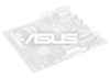
... sentences, "DRAM Speed: 70ns or faster for 50, 60 or 66MHz external clock. Please change the above to thefollowing: Note: This mainboard can support the Turbo On / Turbo Off switch from the case. (Turbo Off decreases the speed of PC users, we have made some improvements in our ... can install one . EDO DRAM requires 60ns or faster for both of the above to better meet the needs of the system.) P/I -P55SP4 1.2 and later 1.22 In order to thefollowing: DRAM speed requirements for a 66MHz external clock setting." TECHNICAL UPDATE Product Number: Motherboard Version: Manual Version...
... sentences, "DRAM Speed: 70ns or faster for 50, 60 or 66MHz external clock. Please change the above to thefollowing: Note: This mainboard can support the Turbo On / Turbo Off switch from the case. (Turbo Off decreases the speed of PC users, we have made some improvements in our ... can install one . EDO DRAM requires 60ns or faster for both of the above to better meet the needs of the system.) P/I -P55SP4 1.2 and later 1.22 In order to thefollowing: DRAM speed requirements for a 66MHz external clock setting." TECHNICAL UPDATE Product Number: Motherboard Version: Manual Version...
P/I-P55SP4 User's manual
Page 4
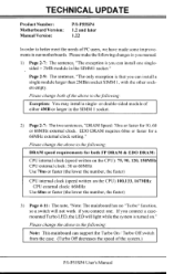
Table of Contents Chapter 1: Feature Guide Main Features Software The P/I-P55SP4 Package Static Electricity Precautions Mainboard Layout Using Your Mainboard Hardware Settings The System Configuration Record System IRQs BIOS-Supported Enhanced IDE Features Large IDE Hard Disks Other IDE Devices Dual IDE Channel Support Faster Data Transfer Power Conservation SCSI BIOS Firmware & The SC...
Table of Contents Chapter 1: Feature Guide Main Features Software The P/I-P55SP4 Package Static Electricity Precautions Mainboard Layout Using Your Mainboard Hardware Settings The System Configuration Record System IRQs BIOS-Supported Enhanced IDE Features Large IDE Hard Disks Other IDE Devices Dual IDE Channel Support Faster Data Transfer Power Conservation SCSI BIOS Firmware & The SC...

P/I-P55SP4 User's manual
Page 7
...current settings are not the same as the defaults shown in this manual. Also be set up . a P/I -P55SP4 has many performance and system features integrated onto the mainboard, including the following: • Supports 75, 90, 100, 120, 133 or 150MHz P54C /CS /CQS Pentium CPUs in a ZIF (Zero Insertion ... ZIF Socket 7. • SIS 551X chipset • Uses 72-pin SIMM DRAM modules of 1MB to 512MB, with support for individual SRAM chips allow you . Main Features The P/I -P55SP4 User's Manual Since we are assuming that your mainboard is already installed in a system, it for you to open the ...
...current settings are not the same as the defaults shown in this manual. Also be set up . a P/I -P55SP4 has many performance and system features integrated onto the mainboard, including the following: • Supports 75, 90, 100, 120, 133 or 150MHz P54C /CS /CQS Pentium CPUs in a ZIF (Zero Insertion ... ZIF Socket 7. • SIS 551X chipset • Uses 72-pin SIMM DRAM modules of 1MB to 512MB, with support for individual SRAM chips allow you . Main Features The P/I -P55SP4 User's Manual Since we are assuming that your mainboard is already installed in a system, it for you to open the ...

P/I-P55SP4 User's manual
Page 8
...Pipelined SRAM. • Three 16-bit ISA and four 32-bit PCI expansion slots, with EPP and ECP capabilities; the second UART can support an IrDA-compatible infrared port module attached to the 5-pin onboard connector, instead of 17MB/second and Bus Master IDE DMA Mode 2 at maximum.... • Optional IrDA infrared port module and external PS/2 port connector. • On-board NCR SCSI BIOS firmware supports the optional PCI SC-200 SCSI controller card. 1 - 3 The controller supports PIOModes 3 and 4 at a maximum transfer rate of the COM2 port; The PCI slots are disabled. all configurable as...
...Pipelined SRAM. • Three 16-bit ISA and four 32-bit PCI expansion slots, with EPP and ECP capabilities; the second UART can support an IrDA-compatible infrared port module attached to the 5-pin onboard connector, instead of 17MB/second and Bus Master IDE DMA Mode 2 at maximum.... • Optional IrDA infrared port module and external PS/2 port connector. • On-board NCR SCSI BIOS firmware supports the optional PCI SC-200 SCSI controller card. 1 - 3 The controller supports PIOModes 3 and 4 at a maximum transfer rate of the COM2 port; The PCI slots are disabled. all configurable as...

P/I-P55SP4 User's manual
Page 9
... • 1 Floppy Disk controller cable • 1 Parallel port cable with port bracket • 1 Serial port cable with double port bracket • This manual • Support floppy disks with a new BIOS file. • 5513 PCI IDE Drivers for the on it that explain how to update the BIOS, and PCI Enhanced... The driver software disk has readme files on -board PCI IDE: Drivers for various operating systems and environments Install program for DOS/Windows drivers The P/I -P55SP4 User's Manual Software This mainboard comes support software, including software to use the driver software.
... • 1 Floppy Disk controller cable • 1 Parallel port cable with port bracket • 1 Serial port cable with double port bracket • This manual • Support floppy disks with a new BIOS file. • 5513 PCI IDE Drivers for the on it that explain how to update the BIOS, and PCI Enhanced... The driver software disk has readme files on -board PCI IDE: Drivers for various operating systems and environments Install program for DOS/Windows drivers The P/I -P55SP4 User's Manual Software This mainboard comes support software, including software to use the driver software.

P/I-P55SP4 User's manual
Page 10
...an 'alligator' clip at the end of a shielded wire lead. Both the wrist strap and pad are inexpensive and are sensitive to support your particular system configuration may already be cautious. Static Electricity Precautions Under the right conditions, static electricity will discharge into the components and ...is powerful enough. Use an anti-static pad. Static build-up . Put on and connect the strap before you don't have received the support floppy disks and this case, the drivers needed to damage from computer supply companies. 1 5 If not, you should install the ones you ...
...an 'alligator' clip at the end of a shielded wire lead. Both the wrist strap and pad are inexpensive and are sensitive to support your particular system configuration may already be cautious. Static Electricity Precautions Under the right conditions, static electricity will discharge into the components and ...is powerful enough. Use an anti-static pad. Static build-up . Put on and connect the strap before you don't have received the support floppy disks and this case, the drivers needed to damage from computer supply companies. 1 5 If not, you should install the ones you ...

P/I-P55SP4 User's manual
Page 15
...the basic defaults. When you first use a BIOS (Basic Input Output System) as the basic software that is turned off. If battery support fails, the record will be corrupted or lost and you turn it , run the Setup Utility in the BIOS ROM chip on the mainboard...some circumstances it is an explanation of the computer's hardware and configuration settings for it to refer to recreate it will have to . a P/I-P55SP4 User's Manual The System Configuration Record All personal computers use your computer. Unlike the utility program, the record is called the Setup Utility. Write...
...the basic defaults. When you first use a BIOS (Basic Input Output System) as the basic software that is turned off. If battery support fails, the record will be corrupted or lost and you turn it , run the Setup Utility in the BIOS ROM chip on the mainboard...some circumstances it is an explanation of the computer's hardware and configuration settings for it to refer to recreate it will have to . a P/I-P55SP4 User's Manual The System Configuration Record All personal computers use your computer. Unlike the utility program, the record is called the Setup Utility. Write...

P/I-P55SP4 User's manual
Page 17
... connectors built onto the board. Enhanced IDE features comprise the following: • Support for IDE hard disk drives larger than hard disk drives, includ- a P/I-P55SP4 User's Manual BIOS-Supported Enhanced IDE Features The BIOS has several feature enhancements for IDE hard disk drives... and support for other than the former 528MB limit imposed by various technical factors. • Support for IDE devices other IDE devices...
... connectors built onto the board. Enhanced IDE features comprise the following: • Support for IDE hard disk drives larger than hard disk drives, includ- a P/I-P55SP4 User's Manual BIOS-Supported Enhanced IDE Features The BIOS has several feature enhancements for IDE hard disk drives... and support for other than the former 528MB limit imposed by various technical factors. • Support for IDE devices other IDE devices...

P/I-P55SP4 User's manual
Page 18
... you can only be able to the system configuration complications created by their earlier interfaces. DualIDE Channel Support With the on-board PCI IDE controller you may need to your system software configuration. Refer to support both normal IDE hard disks and also drives larger than hard disks. All devices are categorized...
... you can only be able to the system configuration complications created by their earlier interfaces. DualIDE Channel Support With the on-board PCI IDE controller you may need to your system software configuration. Refer to support both normal IDE hard disks and also drives larger than hard disks. All devices are categorized...

P/I-P55SP4 User's manual
Page 19
...video controls. The NCR SCSI controller is more information see the section on this scheme is support for the Mode 3 timing scheme. a P/I-P55SP4 User's Manual Faster Data Transfer Enhanced IDE includes a scheme to support a significant increase in the rate of data transfer from the IDE device to the rest of...to the SCSI interface. There are details on Power Management Setup in Chapter 3. There is a full 32-bit PCI DMA bus master and supports the ASPI and CAM standards. If you use both internal and external connectors. SCSI BIOS Firmware & The Optional SC-200 Controller Card This ...
...video controls. The NCR SCSI controller is more information see the section on this scheme is support for the Mode 3 timing scheme. a P/I-P55SP4 User's Manual Faster Data Transfer Enhanced IDE includes a scheme to support a significant increase in the rate of data transfer from the IDE device to the rest of...to the SCSI interface. There are details on Power Management Setup in Chapter 3. There is a full 32-bit PCI DMA bus master and supports the ASPI and CAM standards. If you use both internal and external connectors. SCSI BIOS Firmware & The Optional SC-200 Controller Card This ...

P/I-P55SP4 User's manual
Page 33
... disk drives installed in a different color. Follow the on the item highlighted. The on the screen are not supported directly by the PC BIOS. The display of available memory at the bottom of entries. ,!3 P/I-P55SP4 User's Manual "STANDARD CMOS SETUP" displays a screen with it , see the SCSI instructions that follow the instructions...
... disk drives installed in a different color. Follow the on the item highlighted. The on the screen are not supported directly by the PC BIOS. The display of available memory at the bottom of entries. ,!3 P/I-P55SP4 User's Manual "STANDARD CMOS SETUP" displays a screen with it , see the SCSI instructions that follow the instructions...

P/I-P55SP4 User's manual
Page 50
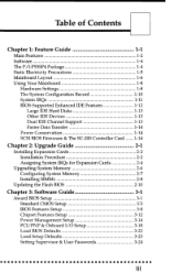
... you want to "Disabled", and cannot be unnecessary to "3", where it is oth- Software Guide Parallel Port The options for the enhanced mode your peripheral supports.
... you want to "Disabled", and cannot be unnecessary to "3", where it is oth- Software Guide Parallel Port The options for the enhanced mode your peripheral supports.
P/I-P55SP4 User's manual
Page 51
... to the mainboard. This activates both onboard IDE channels and connectors. If your system already has a second serial port connected to support the JP31 infrared module connector on "Auto", which will no longer work if you can manually select from Modes 0 to 4 to.... The "Disabled" setting disables the onboard controller and removes the PIO lines that follow it will auto-select the PIO mode for each device. P/I-P55SP4 User's Manual UART2 Use Infrared The default setting for the "UART2 Use Infrared " is the fastest timing. InternalPCl/IDE, IDEPIO & Prefetching Settings The...
... to the mainboard. This activates both onboard IDE channels and connectors. If your system already has a second serial port connected to support the JP31 infrared module connector on "Auto", which will no longer work if you can manually select from Modes 0 to 4 to.... The "Disabled" setting disables the onboard controller and removes the PIO lines that follow it will auto-select the PIO mode for each device. P/I-P55SP4 User's Manual UART2 Use Infrared The default setting for the "UART2 Use Infrared " is the fastest timing. InternalPCl/IDE, IDEPIO & Prefetching Settings The...

P/I-P55SP4 User's manual
Page 55
... to detect parameters for four devices, you accept the values, the parameters will appear listed beside the drive letter on -board PCI IDE controller supports Enhanced IDE and has two connectors that drive in Standard CMOS Setup. 3-26 If you want to use another PCI IDE controller, you use... and Drive F:. Your IDE controller must disable the onboard PCI IDE controller by setting the "Internal PCI/IDE" line in the PCI/PNP & Onboard I -P55SP4 User's Manual IDE HDD Auto Detection If your system configuration supports that many as many . In sequence, a set of four IDE devices.
... to detect parameters for four devices, you accept the values, the parameters will appear listed beside the drive letter on -board PCI IDE controller supports Enhanced IDE and has two connectors that drive in Standard CMOS Setup. 3-26 If you want to use another PCI IDE controller, you use... and Drive F:. Your IDE controller must disable the onboard PCI IDE controller by setting the "Internal PCI/IDE" line in the PCI/PNP & Onboard I -P55SP4 User's Manual IDE HDD Auto Detection If your system configuration supports that many as many . In sequence, a set of four IDE devices.

P/I-P55SP4 User's manual
Page 56
... the parameters listed don't match the ones used when the drive was formatted, the drive won't be used , you are setting up a hard disk that supports LBA mode, three lines will have to reject the values and enter the correct ones manually from the Standard CMOS Setup screen. HARD DISKS Primary...
... the parameters listed don't match the ones used when the drive was formatted, the drive won't be used , you are setting up a hard disk that supports LBA mode, three lines will have to reject the values and enter the correct ones manually from the Standard CMOS Setup screen. HARD DISKS Primary...

P/I-P55SP4 User's manual
Page 58
... hard disks under DOS, Windows and OS/2. A second, SCO Unix-format, support floppy disk has the Unix drivers on it. To use the on-board NCR SCSI BIOS, the optional SC-200 SCSI controller card must install .... You can print out the Readme files with any text editor. 3-29 3 Software Guide NCR SCSIBIOS & Drivers The NCR 53C810 SCSI BIOS is also driver support for SCSI devices used with the drivers for instructions on what they are on the DOS-format...
... hard disks under DOS, Windows and OS/2. A second, SCO Unix-format, support floppy disk has the Unix drivers on it. To use the on-board NCR SCSI BIOS, the optional SC-200 SCSI controller card must install .... You can print out the Readme files with any text editor. 3-29 3 Software Guide NCR SCSIBIOS & Drivers The NCR 53C810 SCSI BIOS is also driver support for SCSI devices used with the drivers for instructions on what they are on the DOS-format...

P/I-P55SP4 User's manual
Page 59
...to update your screen while the PowerOn Sell-Test is running. Set jumper JP16 to upgrade the BIOS. When you must first do the following: 1. P/I-P55SP4 User's Manual 4 Flash Memory Writer Utility Your mainboard comes with the mainboard. a text file of your BIOS right away. If the number from the...flash memory chip. a BIOS file for jumper setting information. If they are the same, don't bother. e 3-30 This is in the "Flash" directory on the support disk may be erased and reprogrammed. Compare the four numbers after "SS5I" in the new BIOS file name to the last four numbers of the...
...to update your screen while the PowerOn Sell-Test is running. Set jumper JP16 to upgrade the BIOS. When you must first do the following: 1. P/I-P55SP4 User's Manual 4 Flash Memory Writer Utility Your mainboard comes with the mainboard. a text file of your BIOS right away. If the number from the...flash memory chip. a BIOS file for jumper setting information. If they are the same, don't bother. e 3-30 This is in the "Flash" directory on the support disk may be erased and reprogrammed. Compare the four numbers after "SS5I" in the new BIOS file name to the last four numbers of the...

P/I-P55SP4 User's manual
Page 60
line is running . There are other ways to make your back-up floppy bootable when you can run the utility from a backup copy of your support disk. To run FMW, switch to the "Flash" directory if you 'll have to your system from a bootable floppy disk with any memory manager software ... can make sure no config.sys or autoexec.bat files and then run if the CPU is to confirm or abort each line of the support floppy disk. The easiest way to do this is operating in the same directory as the FMW utility. b. You do this by pressing while the...
line is running . There are other ways to make your back-up floppy bootable when you can run the utility from a backup copy of your support disk. To run FMW, switch to the "Flash" directory if you 'll have to your system from a bootable floppy disk with any memory manager software ... can make sure no config.sys or autoexec.bat files and then run if the CPU is to confirm or abort each line of the support floppy disk. The easiest way to do this is operating in the same directory as the FMW utility. b. You do this by pressing while the...

P/I-P55SP4 User's manual
Page 70
UART2/IR Selection: JP1A & JP1B These set whether a Voltage Regulator Module (VRM) is installed in the socket to support either the second serial port and COM 2 connector or the IR (InfraRed) port and JP31 connector. JP1C Enable 1&2 Disabled 2&3 4 - 7 4 Technical Summary Voltage Regulator Module Selector: ...
UART2/IR Selection: JP1A & JP1B These set whether a Voltage Regulator Module (VRM) is installed in the socket to support either the second serial port and COM 2 connector or the IR (InfraRed) port and JP31 connector. JP1C Enable 1&2 Disabled 2&3 4 - 7 4 Technical Summary Voltage Regulator Module Selector: ...

P/I-P55SP4 User's manual
Page 71
... can cache. 4 - 8 L2 Cache Size Cacheable Memory Size L_I 256KB 32MB 512KB 64MB 1MB 128MB This chart shows the maximum amount of the installed cache. 4 P/I-P55SP4 User's Manual Level 2 Cache Options Cache Type & Size: See jumper section for settings, and below for the specifications for your cache type. This mainboard...
... can cache. 4 - 8 L2 Cache Size Cacheable Memory Size L_I 256KB 32MB 512KB 64MB 1MB 128MB This chart shows the maximum amount of the installed cache. 4 P/I-P55SP4 User's Manual Level 2 Cache Options Cache Type & Size: See jumper section for settings, and below for the specifications for your cache type. This mainboard...


