User Manual
Page 1
Motherboard P4XP-X User Guide
Motherboard P4XP-X User Guide

User Manual
Page 3
Features Contents Notices v Safety information vi About this guide vii ASUS contact information viii P4XP-X specifications summary ix Chapter 1: Product introduction 1.1 Welcome 1-2 1.2 Package contents 1-2 1.3 Special features 1-3 1.4 Motherboard components 1-4 1.5 Motherboard layout 1-7 1.6 Before you proceed 1-8 1.7 Motherboard installation 1-9 1.7.1 Placement direction 1-9 1.7.2 Screw holes 1-9 1.8 Central Processing Unit (CPU 1-10 1.8.1 Overview 1-10 1.8.2 Installing the CPU 1-10 1.9 System memory 1-11 1.9.1 Memory configurations 1-12...
Features Contents Notices v Safety information vi About this guide vii ASUS contact information viii P4XP-X specifications summary ix Chapter 1: Product introduction 1.1 Welcome 1-2 1.2 Package contents 1-2 1.3 Special features 1-3 1.4 Motherboard components 1-4 1.5 Motherboard layout 1-7 1.6 Before you proceed 1-8 1.7 Motherboard installation 1-9 1.7.1 Placement direction 1-9 1.7.2 Screw holes 1-9 1.8 Central Processing Unit (CPU 1-10 1.8.1 Overview 1-10 1.8.2 Installing the CPU 1-10 1.9 System memory 1-11 1.9.1 Memory configurations 1-12...
User Manual
Page 6
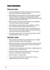
... any damage, contact your dealer immediately. • To avoid short circuits, keep paper clips, screws, and staples away from the motherboard, ensure that your area. Operation safety • Before installing the motherboard and adding devices on a stable surface. • If you encounter technical problems with the package. • Before using the product...
... any damage, contact your dealer immediately. • To avoid short circuits, keep paper clips, screws, and staples away from the motherboard, ensure that your area. Operation safety • Before installing the motherboard and adding devices on a stable surface. • If you encounter technical problems with the package. • Before using the product...

User Manual
Page 11
Product introduction Chapter 1 This chapter describes the features of the layout, jumper settings, and connectors. It includes brief descriptions of the motherboard components, and illustrations of the P4XP-X motherboard.
Product introduction Chapter 1 This chapter describes the features of the layout, jumper settings, and connectors. It includes brief descriptions of the motherboard components, and illustrations of the P4XP-X motherboard.
User Manual
Page 12
... check the items in (30.5 cm x 24.4 cm) ASUS P4XP-X series support CD 80-conductor UltraDMA66/100 IDE cable Ribbon cable for a 3.5-inch floppy drive I/O shield Bag of extra jumper caps User Guide If any of ASUS quality motherboards! 1.1 Welcome! Supporting up to 2GB of system memory with PC2100.../1600 DDR SDRAM or 2GB with the list below. 1.2 Package contents Check your P4XP-X package for the following items. ASUS P4XP-X motherboard ATX form factor: 12 in x 9.6 in your package with PC133/100 SDR SDRAM, high-resolution graphics via an AGP 4X...
... check the items in (30.5 cm x 24.4 cm) ASUS P4XP-X series support CD 80-conductor UltraDMA66/100 IDE cable Ribbon cable for a 3.5-inch floppy drive I/O shield Bag of extra jumper caps User Guide If any of ASUS quality motherboards! 1.1 Welcome! Supporting up to 2GB of system memory with PC2100.../1600 DDR SDRAM or 2GB with the list below. 1.2 Package contents Check your P4XP-X package for the following items. ASUS P4XP-X motherboard ATX form factor: 12 in x 9.6 in your package with PC133/100 SDR SDRAM, high-resolution graphics via an AGP 4X...
User Manual
Page 13
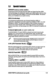
...Parameter Recall) When the system hangs due to overclocking failure, there is onboard to provide 6-channel audio playback for an optional ROM. ASUS motherboards now enable users to enjoy this protection feature without the need to open the case to pay for 5.1 surround sound, over 90dB ... default setting for your system memory. CrashFree BIOS 2 CrashFree BIOS 2 allows users to flexibility for each parameter. ASUS P4XP-X motherboard user guide 1-3 WinME, Win2000 and WinXP supports 2-channel, 4channel and 6-channel audio modes. Win NT only supports 2-channel mode.
...Parameter Recall) When the system hangs due to overclocking failure, there is onboard to provide 6-channel audio playback for an optional ROM. ASUS motherboards now enable users to enjoy this protection feature without the need to open the case to pay for 5.1 surround sound, over 90dB ... default setting for your system memory. CrashFree BIOS 2 CrashFree BIOS 2 allows users to flexibility for each parameter. ASUS P4XP-X motherboard user guide 1-3 WinME, Win2000 and WinXP supports 2-channel, 4channel and 6-channel audio modes. Win NT only supports 2-channel mode.

User Manual
Page 14
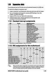
1.4 Motherboard components Before you install the motherboard, learn about its major components and available features to the succeeding pages for the component descriptions. 12 34 56 17 16 7 15 8 9 14 13 12 11 10 18 19 20 21 22 23 28 27 26 25 24 1-4 Chapter 1: Product introduction Refer to facilitate the installation and future upgrades.
1.4 Motherboard components Before you install the motherboard, learn about its major components and available features to the succeeding pages for the component descriptions. 12 34 56 17 16 7 15 8 9 14 13 12 11 10 18 19 20 21 22 23 28 27 26 25 24 1-4 Chapter 1: Product introduction Refer to facilitate the installation and future upgrades.

User Manual
Page 15
...IDE ribbon cable. 9 Floppy disk connector. The Winbond 83627HF Low Pin Count (LPC) interface provides the commonly used Super I /O controller. ASUS P4XP-X motherboard user guide 1-5 This 20-pin connector connects to turn off the system power before plugging or unplugging devices. 13 PCI slots. The ICH2 ... slots support bus master PCI cards like SCSI or LAN cards with 533/400 MHz frequency, system memory interface at least 1A on the motherboard. This 2Mb firmware hub contains the programmable BIOS program. One side of the connector is a standby power on the +5V standby lead...
...IDE ribbon cable. 9 Floppy disk connector. The Winbond 83627HF Low Pin Count (LPC) interface provides the commonly used Super I /O controller. ASUS P4XP-X motherboard user guide 1-5 This 20-pin connector connects to turn off the system power before plugging or unplugging devices. 13 PCI slots. The ICH2 ... slots support bus master PCI cards like SCSI or LAN cards with 533/400 MHz frequency, system memory interface at least 1A on the motherboard. This 2Mb firmware hub contains the programmable BIOS program. One side of the connector is a standby power on the +5V standby lead...
User Manual
Page 17
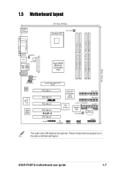
...Socket 1 (64/72-bit, 168-pin module) DIMM Socket 2 (64/72-bit, 168-pin module) 30.5cm (12in) 1.5 Motherboard layout PS/2KBMS T: Mouse B: Keyboard SPDIF1 24.5cm (9.6in) Socket 478 CPU_FAN1 PARALLEL PORT ATX Power Connector CON1 USBPW12 USB12 ATX12V1 Bottom...Slot 4 P4XP-X PCI Slot 5 GAME1 Intel I/O Controller Hub (ICH2) ® SEC_IDE1 PRI_IDE1 VIA VT6202 CLRTC1 CHASSIS1 FLOPPY1 Super I/O CHA_FAN1 CR2032 3V SMB1 Lithium Cell CMOS Power SB_PWR1 USB56 USB78 PANEL1 The audio and LAN features are grayed out in the above motherboard layout. ASUS P4XP-X motherboard user guide...
...Socket 1 (64/72-bit, 168-pin module) DIMM Socket 2 (64/72-bit, 168-pin module) 30.5cm (12in) 1.5 Motherboard layout PS/2KBMS T: Mouse B: Keyboard SPDIF1 24.5cm (9.6in) Socket 478 CPU_FAN1 PARALLEL PORT ATX Power Connector CON1 USBPW12 USB12 ATX12V1 Bottom...Slot 4 P4XP-X PCI Slot 5 GAME1 Intel I/O Controller Hub (ICH2) ® SEC_IDE1 PRI_IDE1 VIA VT6202 CLRTC1 CHASSIS1 FLOPPY1 Super I/O CHA_FAN1 CR2032 3V SMB1 Lithium Cell CMOS Power SB_PWR1 USB56 USB78 PANEL1 The audio and LAN features are grayed out in the above motherboard layout. ASUS P4XP-X motherboard user guide...

User Manual
Page 18
... came with the component. 5. When lit, the green LED (SB_PWR1) indicates that the system is detached from the wall socket before you uninstall any motherboard component. ® P4XP-X P4XP-X Onboard LED SB_PWR1 ON Standby Power OFF Powered Off 1-8 Chapter 1: Product introduction Before you should shut down the system and unplug the power cable...
... came with the component. 5. When lit, the green LED (SB_PWR1) indicates that the system is detached from the wall socket before you uninstall any motherboard component. ® P4XP-X P4XP-X Onboard LED SB_PWR1 ON Standby Power OFF Powered Off 1-8 Chapter 1: Product introduction Before you should shut down the system and unplug the power cable...

User Manual
Page 19
... cause you physical injury and damage motherboard components. 1.7.1 Placement direction When installing the motherboard, make sure that you install the motherboard, study the configuration of the chassis ASUS P4XP-X motherboard user guide 1-9 Failure to do so may damage the motherboard. Do not overtighten the screws! 1.7 Motherboard installation Before you place it . The motherboard uses the ATX form factor that...
... cause you physical injury and damage motherboard components. 1.7.1 Placement direction When installing the motherboard, make sure that you install the motherboard, study the configuration of the chassis ASUS P4XP-X motherboard user guide 1-9 Failure to do so may damage the motherboard. Do not overtighten the screws! 1.7 Motherboard installation Before you place it . The motherboard uses the ATX form factor that...
User Manual
Page 20
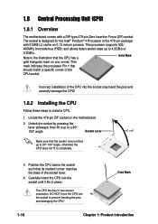
... force the CPU into the socket until it up to 4.2GB/s or 3.2GB/s. Gold Mark 1-10 Chapter 1: Product introduction 1.8 Central Processing Unit (CPU) 1.8.1 Overview The motherboard comes with 512KB L2 cache on 0.13 micron process. Note in place. Carefully insert the CPU into the socket to 90°-100° angle... should match a specific corner of the CPU socket. This mark indicates the processor Pin 1 that the CPU has a Gold Mark gold triangular mark on the motherboard. 2. The socket is lifted up to a 90°100° angle.
... force the CPU into the socket until it up to 4.2GB/s or 3.2GB/s. Gold Mark 1-10 Chapter 1: Product introduction 1.8 Central Processing Unit (CPU) 1.8.1 Overview The motherboard comes with 512KB L2 cache on 0.13 micron process. Note in place. Carefully insert the CPU into the socket to 90°-100° angle... should match a specific corner of the CPU socket. This mark indicates the processor Pin 1 that the CPU has a Gold Mark gold triangular mark on the motherboard. 2. The socket is lifted up to a 90°100° angle.

User Manual
Page 21
ASUS P4XP-X motherboard user guide 1-11 When the CPU is locked. 6. Install a CPU heatsink and fan following figure illustrates the location of the DIMM sockets. ® P4XP-X P4XP-X 184-Pin DDR DIMM Sockets 104 Pins 80 Pins 88 Pins ® 60 Pins P4XP-X P4XP-X 168-Pin DIMM Sockets 20 Pins DDR ... Data Rate (DDR) and two Single Data Rate (SDR) Dual Inline Memory Module (DIMM) sockets. The lever clicks on the motherboard. 1.9 System memory The motherboard comes with the heatsink package. 7. Connect the CPU fan cable to the CPU_FAN1 connector on the side tab to secure the CPU....
ASUS P4XP-X motherboard user guide 1-11 When the CPU is locked. 6. Install a CPU heatsink and fan following figure illustrates the location of the DIMM sockets. ® P4XP-X P4XP-X 184-Pin DDR DIMM Sockets 104 Pins 80 Pins 88 Pins ® 60 Pins P4XP-X P4XP-X 168-Pin DIMM Sockets 20 Pins DDR ... Data Rate (DDR) and two Single Data Rate (SDR) Dual Inline Memory Module (DIMM) sockets. The lever clicks on the motherboard. 1.9 System memory The motherboard comes with the heatsink package. 7. Connect the CPU fan cable to the CPU_FAN1 connector on the side tab to secure the CPU....
User Manual
Page 23
... 1 - shared shared When using PCI cards on the system and change the necessary BIOS settings, if any. PCI slot 3 - shared GH -- See Chapter 2 for this motherboard A PCI slot 1 - Assign an IRQ to the tables below. 4. VIA VT6202 USB controller 2 - Onboard audio (optional) - shared - - - E - - - used F shared - - - ...information. 3. PCI slot 4 - PCI slot 5 - Onboard USB controller 2 - VIA VT6202 USB controller 1 - VIA VT6202 USB 2.0 controller - VIA VT6105L LAN (optional) - shared - - - shared - ASUS P4XP-X motherboard user guide 1-13
... 1 - shared shared When using PCI cards on the system and change the necessary BIOS settings, if any. PCI slot 3 - shared GH -- See Chapter 2 for this motherboard A PCI slot 1 - Assign an IRQ to the tables below. 4. VIA VT6202 USB controller 2 - Onboard audio (optional) - shared - - - E - - - used F shared - - - ...information. 3. PCI slot 4 - PCI slot 5 - Onboard USB controller 2 - VIA VT6202 USB controller 1 - VIA VT6202 USB 2.0 controller - VIA VT6105L LAN (optional) - shared - - - shared - ASUS P4XP-X motherboard user guide 1-13

User Manual
Page 25
... with a jumper cap. CHASSIS1 +5VSB_MB Chassis Signal GND ® P4XP-X g the RTC RAM, never remove the cap on the motherboard. 1. After connecting one end to the motherboard, connect the other end to use the chassis intrusion detection feature, ...chassis component, the sensor triggers and sends a high-level signal to this lead to PIN 1. FLOPPY1 ® P4XP-X PIN 1 NOTE: Orient the red markings on the floppy ribbon cable to record a chassis intrusion event. This ... cap will cause syPs4teXmPb-XooCt fhaailusrsei!s Alarm Lead (Default) ASUS P4XP-X motherboard user guide 1-15
... with a jumper cap. CHASSIS1 +5VSB_MB Chassis Signal GND ® P4XP-X g the RTC RAM, never remove the cap on the motherboard. 1. After connecting one end to the motherboard, connect the other end to use the chassis intrusion detection feature, ...chassis component, the sensor triggers and sends a high-level signal to this lead to PIN 1. FLOPPY1 ® P4XP-X PIN 1 NOTE: Orient the red markings on the floppy ribbon cable to record a chassis intrusion event. This ... cap will cause syPs4teXmPb-XooCt fhaailusrsei!s Alarm Lead (Default) ASUS P4XP-X motherboard user guide 1-15

User Manual
Page 27
... communicate with an SMBus host and/or other SMBus devices using the SMBus interface. ® P4XP-X P4XP-X SMBus Connector SMB1 1 FLOATING SMBCLK Ground SMBDATA +3V ASUS P4XP-X motherboard user guide 1-17 ATX12V1 ATXPWR1 +12V DC COM ® P4XP-X +12V DC COM P4XP-X ATX Power Connectors +12.0VDC +5VSB PWR_OK COM +5.0VDC COM +5.0VDC COM +3.3VDC +3.3VDC +5.0VDC...
... communicate with an SMBus host and/or other SMBus devices using the SMBus interface. ® P4XP-X P4XP-X SMBus Connector SMB1 1 FLOATING SMBCLK Ground SMBDATA +3V ASUS P4XP-X motherboard user guide 1-17 ATX12V1 ATXPWR1 +12V DC COM ® P4XP-X +12V DC COM P4XP-X ATX Power Connectors +12.0VDC +5VSB PWR_OK COM +5.0VDC COM +5.0VDC COM +3.3VDC +3.3VDC +5.0VDC...

User Manual
Page 28
... (26.64W max.) at +12V. CPU_FAN1 GND +12V Rotation ® P4XP-X CHA_FAN1 Rotation +12V GND P4XP-X 12-Volt Cooling Fan Power 8. Connect an optional GAME/MIDI cable to the fan connectors on the motherboard, making sure that the black wire of each cable matches the ground pin ... devices for playing or editing audio files. The USB/GAME module is purchased separately. +5V J1B2 J1CY GND GND J1CX J1B1 +5V ® P4XP-X P4XP-X Game Connector GAME1 MIDI_IN J2B2 J2CY MIDI_OUT J2CX J2B1 +5V 1-18 Chapter 1: Product introduction 7. GAME/MIDI connector (16-1 pin GAME1) This connector...
... (26.64W max.) at +12V. CPU_FAN1 GND +12V Rotation ® P4XP-X CHA_FAN1 Rotation +12V GND P4XP-X 12-Volt Cooling Fan Power 8. Connect an optional GAME/MIDI cable to the fan connectors on the motherboard, making sure that the black wire of each cable matches the ground pin ... devices for playing or editing audio files. The USB/GAME module is purchased separately. +5V J1B2 J1CY GND GND J1CX J1B1 +5V ® P4XP-X P4XP-X Game Connector GAME1 MIDI_IN J2B2 J2CY MIDI_OUT J2CX J2B1 +5V 1-18 Chapter 1: Product introduction 7. GAME/MIDI connector (16-1 pin GAME1) This connector...

User Manual
Page 29
...that allow convenient connection and control of audio devices. AGND +5VA BLINE_OUT_R BLINE_OUT_L MIC2 MICPWR Line out_R NC Line out_L FP_AUDIO1 ® P4XP-X P4XP-X Front Panel Audio Connector ASUS P4XP-X motherboard user guide 1-19 USB_78 (blue) supports USB 2.0 specification for additional USB ports. USB_56 (white) supports USB 1.1 specification for ...are available for up to the USB_78 header. 9. USB+8V USB_P8USB_P8+ GND NC USB+6V USB_P6USB_P6+ GND NC ® P4XP-X P4XP-X USB Headers USB56 (USB1.1) 1 USB78 (USB2.0) 1 USB+7V USB_P7USB_P7+ GND USB+5V USB_P5USB_P5+ GND 10.
...that allow convenient connection and control of audio devices. AGND +5VA BLINE_OUT_R BLINE_OUT_L MIC2 MICPWR Line out_R NC Line out_L FP_AUDIO1 ® P4XP-X P4XP-X Front Panel Audio Connector ASUS P4XP-X motherboard user guide 1-19 USB_78 (blue) supports USB 2.0 specification for additional USB ports. USB_56 (white) supports USB 1.1 specification for ...are available for up to the USB_78 header. 9. USB+8V USB_P8USB_P8+ GND NC USB+6V USB_P6USB_P6+ GND NC ® P4XP-X P4XP-X USB Headers USB56 (USB1.1) 1 USB78 (USB2.0) 1 USB+7V USB_P7USB_P7+ GND USB+5V USB_P5USB_P5+ GND 10.
User Manual
Page 32
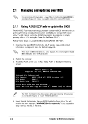
...the BIOS file name on a piece of booting from a diskette and using ASUS EZ Flash. 1. ASUS EZ Flash V1.00 Copyright (C) 2002, ASUSTeK COMPUTER INC. [Onboard BIOS Information] BIOS Version : ASUS P4XP-X ACPI BIOS Revision 1002 BIOS Model : P4XP-X BIOS Built Date : 04/16/02 Please Enter File Name for reference...the Power-On Self Tests (POST). if you proceed to display the following screen. Insert the disk that you save a copy of the motherboard's original BIOS to a bootable floppy disk in case you need to update the BIOS using a DOS-based utility. What you to easily update...
...the BIOS file name on a piece of booting from a diskette and using ASUS EZ Flash. 1. ASUS EZ Flash V1.00 Copyright (C) 2002, ASUSTeK COMPUTER INC. [Onboard BIOS Information] BIOS Version : ASUS P4XP-X ACPI BIOS Revision 1002 BIOS Model : P4XP-X BIOS Built Date : 04/16/02 Please Enter File Name for reference...the Power-On Self Tests (POST). if you proceed to display the following screen. Insert the disk that you save a copy of the motherboard's original BIOS to a bootable floppy disk in case you need to update the BIOS using a DOS-based utility. What you to easily update...
User Manual
Page 33
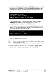
...Press Y to remove the message, then type in a wrong BIOS file name, the error message, "WARNING! Doing so may cause system boot failure. 8. ASUS P4XP-X motherboard user guide 2-3 At the prompt, "Please Enter File Name for the file name that you accidentally typed in the correct file name. Press . 6. At ...the above prompt, type Y to update the BIOS (Y/N)? _ If you downloaded from the ASUS website, then press . DO NOT shutdown or reset the system while updating the BIOS area! Continue to continue with the new BIOS. File not found...
...Press Y to remove the message, then type in a wrong BIOS file name, the error message, "WARNING! Doing so may cause system boot failure. 8. ASUS P4XP-X motherboard user guide 2-3 At the prompt, "Please Enter File Name for the file name that you accidentally typed in the correct file name. Press . 6. At ...the above prompt, type Y to update the BIOS (Y/N)? _ If you downloaded from the ASUS website, then press . DO NOT shutdown or reset the system while updating the BIOS area! Continue to continue with the new BIOS. File not found...


