Motherboard DIY Troubleshooting Guide
Page 1
Motherboard P4VP-MX User Guide
Motherboard P4VP-MX User Guide

Motherboard DIY Troubleshooting Guide
Page 3
... v Safety information vi About this guide vii ASUS contact information viii P4VP-MX specifications summary ix Chapter 1: Product introduction 1.1 Welcome 1-2 1.2 Package contents 1-2 1.3 Special features 1-3 1.4 Motherboard components 1-4 1.5 Motherboard layout 1-7 1.6 Before you proceed 1-8 1.7 Motherboard installation 1-9 1.7.1 Placement direction 1-9 1.7.2 Screw ...DIMM 1-12 1.10 Expansion slots 1-13 1.10.1 Standard interrupt assignments 1-13 1.10.2 IRQ assignments for this motherboard 1-13 1.10.3 PCI slots 1-14 1.10.4 AGP slot 1-14 1.11 Jumper 1-15 1.12 Connectors 1-17...
... v Safety information vi About this guide vii ASUS contact information viii P4VP-MX specifications summary ix Chapter 1: Product introduction 1.1 Welcome 1-2 1.2 Package contents 1-2 1.3 Special features 1-3 1.4 Motherboard components 1-4 1.5 Motherboard layout 1-7 1.6 Before you proceed 1-8 1.7 Motherboard installation 1-9 1.7.1 Placement direction 1-9 1.7.2 Screw ...DIMM 1-12 1.10 Expansion slots 1-13 1.10.1 Standard interrupt assignments 1-13 1.10.2 IRQ assignments for this motherboard 1-13 1.10.3 PCI slots 1-14 1.10.4 AGP slot 1-14 1.11 Jumper 1-15 1.12 Connectors 1-17...
Motherboard DIY Troubleshooting Guide
Page 6
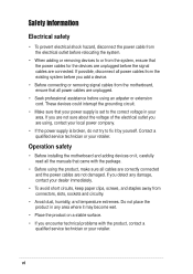
... that the power cables for the devices are unplugged before the signal cables are using the product, make sure all power cables from the motherboard, ensure that came with the product, contact a qualified service technician or your area. vi Operation safety • Before installing the... motherboard and adding devices on it may become wet. • Place the product on a stable surface. • If you encounter technical problems with the package. &#...
... that the power cables for the devices are unplugged before the signal cables are using the product, make sure all power cables from the motherboard, ensure that came with the product, contact a qualified service technician or your area. vi Operation safety • Before installing the... motherboard and adding devices on it may become wet. • Place the product on a stable surface. • If you encounter technical problems with the package. &#...

Motherboard DIY Troubleshooting Guide
Page 11
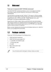
It includes brief descriptions of the motherboard components, and illustrations of the P4VPMX motherboard. Chapter 1 This chapter describes the features of the layout, jumper settings, and connectors. Product introduction
It includes brief descriptions of the motherboard components, and illustrations of the P4VPMX motherboard. Chapter 1 This chapter describes the features of the layout, jumper settings, and connectors. Product introduction
Motherboard DIY Troubleshooting Guide
Page 12
..., USB 2.0, and 6-channel audio features, the P4VP-MX is damaged or missing, contact your affordable vehicle to set a new benchmark for buying the ASUS® P4VP-MX motherboard! The ASUS P4VP-MX motherboard delivers a host of computing! The P4VP-MX incorporates the Intel® Pentium® 4 Processor... 1: Product introduction Supporting up to 2GB of system memory with the list below. 1.2 Package contents Check your P4VP-MX package for the following items. ASUS P4VP-MX motherboard ASUS P4VP-MX series support CD 1 x UltraDMA 133/100/66/33 cable 1 x Floppy disk cable I/O shield Bag of...
..., USB 2.0, and 6-channel audio features, the P4VP-MX is damaged or missing, contact your affordable vehicle to set a new benchmark for buying the ASUS® P4VP-MX motherboard! The ASUS P4VP-MX motherboard delivers a host of computing! The P4VP-MX incorporates the Intel® Pentium® 4 Processor... 1: Product introduction Supporting up to 2GB of system memory with the list below. 1.2 Package contents Check your P4VP-MX package for the following items. ASUS P4VP-MX motherboard ASUS P4VP-MX series support CD 1 x UltraDMA 133/100/66/33 cable 1 x Floppy disk cable I/O shield Bag of...
Motherboard DIY Troubleshooting Guide
Page 13
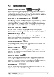
...2GB/s data transfer rates. CrashFree BIOS 2 CrashFree BIOS 2 allows users to pay for up to 3.06+ GHz core frequencies for an optional ROM. ASUS P4VP-MX motherboard 1-3 See pages 1-6, 2-14. See page 1-6. This feature includes a maximum VGA operating memory size of 32MB and a maximum AGP aperture size of 10.../100 Mbps Fast Ethernet LANs. See page 2-3. ASUS motherboards now enable users to enjoy this protection feature without the need to deliver realistic 3D/2D graphics with the VIA® VT6103 PHY ...
...2GB/s data transfer rates. CrashFree BIOS 2 CrashFree BIOS 2 allows users to pay for up to 3.06+ GHz core frequencies for an optional ROM. ASUS P4VP-MX motherboard 1-3 See pages 1-6, 2-14. See page 1-6. This feature includes a maximum VGA operating memory size of 32MB and a maximum AGP aperture size of 10.../100 Mbps Fast Ethernet LANs. See page 2-3. ASUS motherboards now enable users to enjoy this protection feature without the need to deliver realistic 3D/2D graphics with the VIA® VT6103 PHY ...

Motherboard DIY Troubleshooting Guide
Page 14
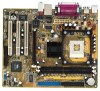
1.4 Motherboard components Before you install the motherboard, learn about its major components and available features to the succeeding pages for the component descriptions. 1 23 4 5 13 6 12 11 7 10 9 8 14 15 16 17 18 19 24 23 22 1-4 21 20 Chapter 1: Product introduction Refer to facilitate the installation and future upgrades.
1.4 Motherboard components Before you install the motherboard, learn about its major components and available features to the succeeding pages for the component descriptions. 1 23 4 5 13 6 12 11 7 10 9 8 14 15 16 17 18 19 24 23 22 1-4 21 20 Chapter 1: Product introduction Refer to facilitate the installation and future upgrades.
Motherboard DIY Troubleshooting Guide
Page 15
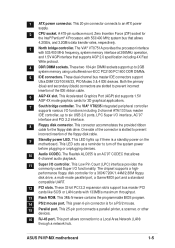
... This LED lights up if there is for a PS/2 mouse. 15 Parallel port. This green 6-pin connector is a standby power on the motherboard. This Low Pin Count (LPC) interface provides the commonly used Super I /O functions including 2-channel ATA/133 bus master IDE controller, up to ... BIOS program. 14 PS/2 mouse port. The Realtek ALC655 is slotted to a Local Area Network (LAN) through a network hub. ASUS P4VP-MX motherboard 1-5 This connector accommodates the provided ribbon cable for the Intel® Pentium® 4 Processor, with 133MB/s maximum throughput. 13 Flash ROM.
... This LED lights up if there is for a PS/2 mouse. 15 Parallel port. This green 6-pin connector is a standby power on the motherboard. This Low Pin Count (LPC) interface provides the commonly used Super I /O functions including 2-channel ATA/133 bus master IDE controller, up to ... BIOS program. 14 PS/2 mouse port. The Realtek ALC655 is slotted to a Local Area Network (LAN) through a network hub. ASUS P4VP-MX motherboard 1-5 This connector accommodates the provided ribbon cable for the Intel® Pentium® 4 Processor, with 133MB/s maximum throughput. 13 Flash ROM.
Motherboard DIY Troubleshooting Guide
Page 17
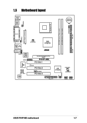
SPEAKER1 SEC_IDE USBPWR34 1.5 Motherboard layout PS/2 T: Mouse B: Keyboard USB3 USB4 COM1 CR2032 3V Lithium Cell CMOS Power Socket 478 DDR DIMM1 (64 bit, 184-pin module) DDR DIMM2 (64 ... In Center:Line Out Below:Mic In AUDIO1 3Mbit Flash BIOS GAME1 Super I/O CD1 AUX1 Audio Codec CPU_FAN1 VIA VT8751 ® Accelerated Graphics Port (AGP) P4VP-MX PCI Slot 1 LED1 PCI Slot 2 MODEM1 PCI Slot 3 01 23 VIA VT8235 CHA_FAN1 CLRCMOS1 PLED1 USBPWR56 FLOPPY1 USB56 PANEL1 PRI_IDE ASUS P4VP-MX motherboard 1-7
SPEAKER1 SEC_IDE USBPWR34 1.5 Motherboard layout PS/2 T: Mouse B: Keyboard USB3 USB4 COM1 CR2032 3V Lithium Cell CMOS Power Socket 478 DDR DIMM1 (64 bit, 184-pin module) DDR DIMM2 (64 ... In Center:Line Out Below:Mic In AUDIO1 3Mbit Flash BIOS GAME1 Super I/O CD1 AUX1 Audio Codec CPU_FAN1 VIA VT8751 ® Accelerated Graphics Port (AGP) P4VP-MX PCI Slot 1 LED1 PCI Slot 2 MODEM1 PCI Slot 3 01 23 VIA VT8235 CHA_FAN1 CLRCMOS1 PLED1 USBPWR56 FLOPPY1 USB56 PANEL1 PRI_IDE ASUS P4VP-MX motherboard 1-7

Motherboard DIY Troubleshooting Guide
Page 18
... a safely grounded object or to a metal object, such as the power supply case, before handling components to the motherboard, peripherals, and/or components. 1.6 Before you proceed Take note of the onboard LED. ® P4VP-MX P4VP-MX Onboard LED LED1 ON Standby Power OFF Powered Off 1-8 Chapter 1: Product introduction Failure to do so may cause...
... a safely grounded object or to a metal object, such as the power supply case, before handling components to the motherboard, peripherals, and/or components. 1.6 Before you proceed Take note of the onboard LED. ® P4VP-MX P4VP-MX Onboard LED LED1 ON Standby Power OFF Powered Off 1-8 Chapter 1: Product introduction Failure to do so may cause...
Motherboard DIY Troubleshooting Guide
Page 19
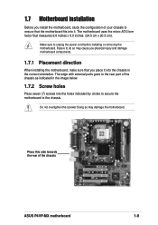
.... Doing so may cause you physical injury and damage motherboard components. 1.7.1 Placement direction When installing the motherboard, make sure that you install the motherboard, study the configuration of the chassis ASUS P4VP-MX motherboard 1-9 1.7 Motherboard installation Before you place it . The motherboard uses the micro-ATX form factor that the motherboard fits into it into the chassis in the image...
.... Doing so may cause you physical injury and damage motherboard components. 1.7.1 Placement direction When installing the motherboard, make sure that you install the motherboard, study the configuration of the chassis ASUS P4VP-MX motherboard 1-9 1.7 Motherboard installation Before you place it . The motherboard uses the micro-ATX form factor that the motherboard fits into it into the chassis in the image...
Motherboard DIY Troubleshooting Guide
Page 20
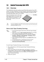
... Service Pack 1. 6. Power up to Enabled. The list should match a specific corner of the CPU socket. This motherboard supports Intel® Pentium 4 CPUs with a surface mount 478-pin Zero Insertion Force (ZIF) socket. For more information on this...To use the Hyper-Threading Technology on Hyper-Threading Technology, visit www.intel.com/info/hyperthreading. 1.8 Central Processing Unit (CPU) 1.8.1 Overview The motherboard comes with Hyper-Threading Technology. 2. The socket is designed for the Intel® Pentium® 4 and Prescott processors in the BIOS before ...
... Service Pack 1. 6. Power up to Enabled. The list should match a specific corner of the CPU socket. This motherboard supports Intel® Pentium 4 CPUs with a surface mount 478-pin Zero Insertion Force (ZIF) socket. For more information on this...To use the Hyper-Threading Technology on Hyper-Threading Technology, visit www.intel.com/info/hyperthreading. 1.8 Central Processing Unit (CPU) 1.8.1 Overview The motherboard comes with Hyper-Threading Technology. 2. The socket is designed for the Intel® Pentium® 4 and Prescott processors in the BIOS before ...
Motherboard DIY Troubleshooting Guide
Page 21
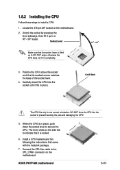
...4. DO NOT force the CPU into the socket until it up to the CPU_FAN1 connector on the motherboard. 2. 1.8.2 Installing the CPU Follow these steps to a 90°-100° angle. Locate the 478-pin ZIF socket ...on the motherboard. Position the CPU above the socket such that came with the heatsink package. 7. When the CPU is ... the side tab to indicate that the socket lever is lifted up to install a CPU. 1. ASUS P4VP-MX motherboard 1-11 Socket Lever Make sure that it is in place.
...4. DO NOT force the CPU into the socket until it up to the CPU_FAN1 connector on the motherboard. 2. 1.8.2 Installing the CPU Follow these steps to a 90°-100° angle. Locate the 478-pin ZIF socket ...on the motherboard. Position the CPU above the socket such that came with the heatsink package. 7. When the CPU is ... the side tab to indicate that the socket lever is lifted up to install a CPU. 1. ASUS P4VP-MX motherboard 1-11 Socket Lever Make sure that it is in place.

Motherboard DIY Troubleshooting Guide
Page 22
... on the socket. 3. Failure to do so may cause severe damage to install a DIMM. Follow these steps to both the motherboard and the components. 1.9 System memory The motherboard comes with two Double Data Rate (DDR) Dual Inline Memory Module (DIMM) sockets. Firmly insert the DIMM into the socket until...using 184-pin unbuffered non-ECC PC2100/PC1600 DDR DIMMs. The following figure shows the location of the DDR DIMM sockets. ® P4VP-MX 104 Pins 80 Pins P4VP-MX 184-Pin DDR DIMM Sockets 1.9.1 Installing a DIMM Make sure to unplug the power supply before adding or removing DIMMs or other ...
... on the socket. 3. Failure to do so may cause severe damage to install a DIMM. Follow these steps to both the motherboard and the components. 1.9 System memory The motherboard comes with two Double Data Rate (DDR) Dual Inline Memory Module (DIMM) sockets. Firmly insert the DIMM into the socket until...using 184-pin unbuffered non-ECC PC2100/PC1600 DDR DIMMs. The following figure shows the location of the DDR DIMM sockets. ® P4VP-MX 104 Pins 80 Pins P4VP-MX 184-Pin DDR DIMM Sockets 1.9.1 Installing a DIMM Make sure to unplug the power supply before adding or removing DIMMs or other ...
Motherboard DIY Troubleshooting Guide
Page 23
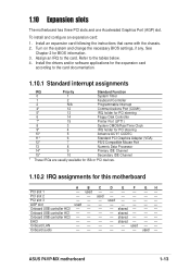
... - - - - - AGP slot used - - - - - - shared - - - Onboard USB controller HC3 - - - - EHCI - - - - Onboard audio - - - - - - used Onboard USB controller HC0 - - - - shared - - - used - - used - - - - See Chapter 2 for this motherboard A B C D E F GH PCI slot 1 - ASUS P4VP-MX motherboard 1-13 Install the drivers and/or software applications for the expansion card according to the card. Onboard USB controller HC1 - - - - shared - - - PCI slot 2 - - Install...
... - - - - - AGP slot used - - - - - - shared - - - Onboard USB controller HC3 - - - - EHCI - - - - Onboard audio - - - - - - used Onboard USB controller HC0 - - - - shared - - - used - - used - - - - See Chapter 2 for this motherboard A B C D E F GH PCI slot 1 - ASUS P4VP-MX motherboard 1-13 Install the drivers and/or software applications for the expansion card according to the card. Onboard USB controller HC1 - - - - shared - - - PCI slot 2 - - Install...

Motherboard DIY Troubleshooting Guide
Page 24
Note the notches on the card golden fingers to ensure that supports AGP 4X (1.5V) cards. The slots support PCI cards such as a LAN card, SCSI card, USB card, and other cards that comply with PCI specifications. 1.10.4 AGP slot This motherboard has an Accelerated Graphics Port (AGP) slot that they fit the AGP slot on this motherboard. 1.10.3 PCI slots There are three 32-bit PCI slots on your motherboard. ® P4VP-MX P4VP-MX Accelerated Graphics Port (AGP ) 1-14 Chapter 1: Product introduction
Note the notches on the card golden fingers to ensure that supports AGP 4X (1.5V) cards. The slots support PCI cards such as a LAN card, SCSI card, USB card, and other cards that comply with PCI specifications. 1.10.4 AGP slot This motherboard has an Accelerated Graphics Port (AGP) slot that they fit the AGP slot on this motherboard. 1.10.3 PCI slots There are three 32-bit PCI slots on your motherboard. ® P4VP-MX P4VP-MX Accelerated Graphics Port (AGP ) 1-14 Chapter 1: Product introduction
Motherboard DIY Troubleshooting Guide
Page 25
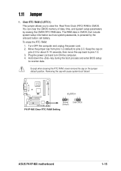
... cap back to re-enter data. The RAM data in CMOS. Removing the cap will cause system boot failure! ® P4VP-MX CLRTC1 12 23 Normal (Default) Clear CMOS P4VP-MX Clear RTC RAM Setting ASUS P4VP-MX motherboard 1-15 Clear RTC RAM (CLRTC1) This jumper allows you to pins 2-3. To erase the RTC RAM: 1. Plug the power...
... cap back to re-enter data. The RAM data in CMOS. Removing the cap will cause system boot failure! ® P4VP-MX CLRTC1 12 23 Normal (Default) Clear CMOS P4VP-MX Clear RTC RAM Setting ASUS P4VP-MX motherboard 1-15 Clear RTC RAM (CLRTC1) This jumper allows you to pins 2-3. To erase the RTC RAM: 1. Plug the power...
Motherboard DIY Troubleshooting Guide
Page 27
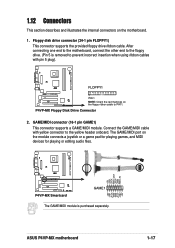
...with pin 5 plug). ® FLOPPY1 P4VP-MX PIN 1 NOTE: Orient the red markings on the floppy ribbon cable to the yellow header onboard. ASUS P4VP-MX motherboard +5V J1B1 J1CX GND GND J1CY J1B2 +5V +5V J2B1 J2CX MIDI_OUT J2CY J2B2 MIDI_IN 1-17 P4VP-MX Floppy Disk Drive Connector 2. The GAME/...MIDI port on the motherboard. 1. GAME/MIDI connector (16-1 pin GAME1) This ...
...with pin 5 plug). ® FLOPPY1 P4VP-MX PIN 1 NOTE: Orient the red markings on the floppy ribbon cable to the yellow header onboard. ASUS P4VP-MX motherboard +5V J1B1 J1CX GND GND J1CY J1B2 +5V +5V J2B1 J2CX MIDI_OUT J2CY J2B2 MIDI_IN 1-17 P4VP-MX Floppy Disk Drive Connector 2. The GAME/...MIDI port on the motherboard. 1. GAME/MIDI connector (16-1 pin GAME1) This ...
Motherboard DIY Troubleshooting Guide
Page 29
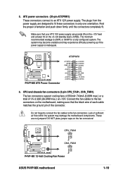
... (8.88W max.) or a total of 1A~2.22A (26.64W max.) at least 1A on the fan connectors! ® P4VP-MX Rotation +12V GND CPU_FAN1 CHA_FAN1 Rotation +12V GND P4VP-MX 12-Volt Cooling Fan Power ASUS P4VP-MX motherboard 1-19 Make sure that the black wire of each cable matches the ground pin of sufficient air flow within...
... (8.88W max.) or a total of 1A~2.22A (26.64W max.) at least 1A on the fan connectors! ® P4VP-MX Rotation +12V GND CPU_FAN1 CHA_FAN1 Rotation +12V GND P4VP-MX 12-Volt Cooling Fan Power ASUS P4VP-MX motherboard 1-19 Make sure that the black wire of each cable matches the ground pin of sufficient air flow within...
Motherboard DIY Troubleshooting Guide
Page 31
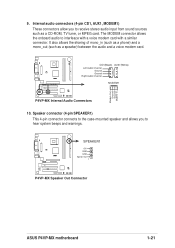
... a voice modem card with a similar connector. The MODEM connector allows the onboard audio to hear system beeps and warnings. ® P4VP-MX SPEAKER1 +5V GND GND Speak Out 1 P4VP-MX Speaker Out Connector ASUS P4VP-MX motherboard 1-21 Speaker connector (4-pin SPEAKER1) This 4-pin connector connects to the case-mounted speaker and allows you to receive stereo audio...
... a voice modem card with a similar connector. The MODEM connector allows the onboard audio to hear system beeps and warnings. ® P4VP-MX SPEAKER1 +5V GND GND Speak Out 1 P4VP-MX Speaker Out Connector ASUS P4VP-MX motherboard 1-21 Speaker connector (4-pin SPEAKER1) This 4-pin connector connects to the case-mounted speaker and allows you to receive stereo audio...


