
Motherboard DIY Troubleshooting Guide
Page 1
Motherboard P4V800D-X User Guide
Motherboard P4V800D-X User Guide

Motherboard DIY Troubleshooting Guide
Page 3
Contents Notices ...v Safety Information vi About This Guide vii P4V800D-X Specifications Summary viii Chapter 1: Product Introduction 1.1 Welcome 1-2 1.2 Package Contents 1-2 1.3 Special Features 1-2 1.3.1 Product highlights 1-2 1.3.2 Innovative ASUS features 1-4 1.4 Before You Proceed 1-5 1.5 Motherboard Overview 1-6 1.5.1 Motherboard layout 1-6 1.5.2 Placement direction 1-7 1.5.3 Screw holes 1-7 1.6 Central Processing Unit (CPU 1-8 1.6.1 Overview 1-8 1.6.2 Installing the CPU 1-8 1.7 System Memory 1-9 1.7.1 Overview 1-9 1.7.2 Memory configurations 1-9 1.7.3 ...
Contents Notices ...v Safety Information vi About This Guide vii P4V800D-X Specifications Summary viii Chapter 1: Product Introduction 1.1 Welcome 1-2 1.2 Package Contents 1-2 1.3 Special Features 1-2 1.3.1 Product highlights 1-2 1.3.2 Innovative ASUS features 1-4 1.4 Before You Proceed 1-5 1.5 Motherboard Overview 1-6 1.5.1 Motherboard layout 1-6 1.5.2 Placement direction 1-7 1.5.3 Screw holes 1-7 1.6 Central Processing Unit (CPU 1-8 1.6.1 Overview 1-8 1.6.2 Installing the CPU 1-8 1.7 System Memory 1-9 1.7.1 Overview 1-9 1.7.2 Memory configurations 1-9 1.7.3 ...

Motherboard DIY Troubleshooting Guide
Page 6
... retailer. vi Do not place the product in your area. If you are using the product, make sure all power cables from the motherboard, ensure that came with the product, contact a qualified service technician or your retailer. Operation safety • Before installing the... motherboard and adding devices on a stable surface. • If you add a device. • Before connecting or removing signal cables from the existing system before ...
... retailer. vi Do not place the product in your area. If you are using the product, make sure all power cables from the motherboard, ensure that came with the product, contact a qualified service technician or your retailer. Operation safety • Before installing the... motherboard and adding devices on a stable surface. • If you add a device. • Before connecting or removing signal cables from the existing system before ...

Motherboard DIY Troubleshooting Guide
Page 7
...the features of the standard package. IMPORTANT: Information that you MUST follow to the ASUS contact information. 2. vii Detailed descriptions of the BIOS parameters are not part of the motherboard and the new technology it supports. WARNING: Information to prevent injury to yourself ...and software products. It also lists the hardware setup procedures that you have been added by your dealer. ASUS websites The ASUS websites worldwide provide updated information on the motherboard. • Chapter 2: BIOS Information This chapter tells how to complete a task. Where to fi...
...the features of the standard package. IMPORTANT: Information that you MUST follow to the ASUS contact information. 2. vii Detailed descriptions of the BIOS parameters are not part of the motherboard and the new technology it supports. WARNING: Information to prevent injury to yourself ...and software products. It also lists the hardware setup procedures that you have been added by your dealer. ASUS websites The ASUS websites worldwide provide updated information on the motherboard. • Chapter 2: BIOS Information This chapter tells how to complete a task. Where to fi...

Motherboard DIY Troubleshooting Guide
Page 11
This chapter describes the motherboard features and the new technologies it supports. 1Product Introduction
This chapter describes the motherboard features and the new technologies it supports. 1Product Introduction

Motherboard DIY Troubleshooting Guide
Page 12
See page 1-9 for details. 1-2 Chapter 1: Product Introduction See page 1-19 for details. System bottlenecks are eliminated with the list below. 1.2 Package contents Check your motherboard package for the following items. Motherboard ASUS P4V800D-X motherboard Cables 1 x Ultra 133/100/66 DMA cable 1 x Serial ATA cable 1 x Serial ATA power cable 1 x Floppy Disk Drive cable Accessories I/O shield Application CDs...
See page 1-9 for details. 1-2 Chapter 1: Product Introduction See page 1-19 for details. System bottlenecks are eliminated with the list below. 1.2 Package contents Check your motherboard package for the following items. Motherboard ASUS P4V800D-X motherboard Cables 1 x Ultra 133/100/66 DMA cable 1 x Serial ATA cable 1 x Serial ATA power cable 1 x Floppy Disk Drive cable Accessories I/O shield Application CDs...

Motherboard DIY Troubleshooting Guide
Page 13
See page 1-17 for details. See pages1-17 & 1-20 for details. ASUS P4V800D-X Motherboard 1-3 USB 2.0 technology USB 2.0 is the latest connectivity standard for easy connectivity and ultra-fast data transfer rate. Backwards compatible with current USB 1.1 ... point-to-point serial interconnections between devices and allows higher clockspeeds by carrying data in this motherboard to give you a fast and reliable connection to 2.13 GB/s. Coaxial S/PDIF out This motherboard provides convenient connectivity to analog format and keeps the best signal quality. PCI Express Interface The...
See page 1-17 for details. See pages1-17 & 1-20 for details. ASUS P4V800D-X Motherboard 1-3 USB 2.0 technology USB 2.0 is the latest connectivity standard for easy connectivity and ultra-fast data transfer rate. Backwards compatible with current USB 1.1 ... point-to-point serial interconnections between devices and allows higher clockspeeds by carrying data in this motherboard to give you a fast and reliable connection to 2.13 GB/s. Coaxial S/PDIF out This motherboard provides convenient connectivity to analog format and keeps the best signal quality. PCI Express Interface The...

Motherboard DIY Troubleshooting Guide
Page 14
1.3.2 Innovative ASUS features ASUS CrashFree BIOS 2 The CrashFree BIOS2 feature now includes the BIOS auto-recovery function in the motherboard allows you can amend the CPU setting again. No more DOS-based flash utility and bootable diskette required. Just simply restart the system, the BIOS ... Users can reboot their system through the support CD when a bootable disk is no need to clear CMOS data. See page 2-6 for an optional ROM. ASUS motherboards now enable users to enjoy this protection feature without the need to open the case to pay for details.
1.3.2 Innovative ASUS features ASUS CrashFree BIOS 2 The CrashFree BIOS2 feature now includes the BIOS auto-recovery function in the motherboard allows you can amend the CPU setting again. No more DOS-based flash utility and bootable diskette required. Just simply restart the system, the BIOS ... Users can reboot their system through the support CD when a bootable disk is no need to clear CMOS data. See page 2-6 for an optional ROM. ASUS motherboards now enable users to enjoy this protection feature without the need to open the case to pay for details.

Motherboard DIY Troubleshooting Guide
Page 15
... or touch a safely grounded object or a metal object, such as the power supply case, before you install motherboard components or change any motherboard settings. • Unplug the power cord from the power supply. The illustration below shows the location of the ...power LED that lights up to the motherboard, peripherals, and/or components. 1.4 Before you proceed Take note of the onboard LED. P4V800D-X ® SB_PWR P4V800D-X Onboard LED ON Standby Power OFF Powered Off ASUS P4V800D-X Motherboard 1-5 Onboard LED The motherboard comes with the component. • Before...
... or touch a safely grounded object or a metal object, such as the power supply case, before you install motherboard components or change any motherboard settings. • Unplug the power cord from the power supply. The illustration below shows the location of the ...power LED that lights up to the motherboard, peripherals, and/or components. 1.4 Before you proceed Take note of the onboard LED. P4V800D-X ® SB_PWR P4V800D-X Onboard LED ON Standby Power OFF Powered Off ASUS P4V800D-X Motherboard 1-5 Onboard LED The motherboard comes with the component. • Before...

Motherboard DIY Troubleshooting Guide
Page 17
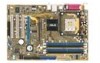
Do not overtighten the screws! Place this side towards-the rear of the chassis as indicated in the image below. 1.5.3 Screw holes Place six screws into the chassis in the correct orientation. Doing so can damage the motherboard. 1.5.2 Placement direction When installing the motherboard, make sure that you place it into the holes indicated by circles to secure the motherboard to the chassis. The edge with external ports goes to the rear part of the chassis P4V800D-X ® ASUS P4V800D-X Motherboard 1-7
Do not overtighten the screws! Place this side towards-the rear of the chassis as indicated in the image below. 1.5.3 Screw holes Place six screws into the chassis in the correct orientation. Doing so can damage the motherboard. 1.5.2 Placement direction When installing the motherboard, make sure that you place it into the holes indicated by circles to secure the motherboard to the chassis. The edge with external ports goes to the rear part of the chassis P4V800D-X ® ASUS P4V800D-X Motherboard 1-7

Motherboard DIY Troubleshooting Guide
Page 18
1.6 Central Processing Unit (CPU) 1.6.1 Overview The motherboard has a Socket for bent pins. 1-8 Chapter 1: Product Introduction This corner is usually indicated with the correct orientation. Locate the CPU socket. Do not force the ... the CPU does not fit, check its alignment and look for installation. The CPU should be oriented toward the inner corner of less than 1GHz. P4V800D-X ® P4V800D-X Socket 478 Gold Arrow 1.6.2 Installing the CPU Follow these steps to the lever hinge.
1.6 Central Processing Unit (CPU) 1.6.1 Overview The motherboard has a Socket for bent pins. 1-8 Chapter 1: Product Introduction This corner is usually indicated with the correct orientation. Locate the CPU socket. Do not force the ... the CPU does not fit, check its alignment and look for installation. The CPU should be oriented toward the inner corner of less than 1GHz. P4V800D-X ® P4V800D-X Socket 478 Gold Arrow 1.6.2 Installing the CPU Follow these steps to the lever hinge.

Motherboard DIY Troubleshooting Guide
Page 19
...latest Qualified Vendor List. DIMM_A1 DIMM_A2 DIMM_B1 DIMM_B2 80 Pins 104 Pins 1.7 System memory 1.7.1 Overview The motherboard has four Double Data Rate (DDR) DIMM sockets that it is keyed with more than 8 devices on each side... (www.asus.com) for a list of the module are the same or set to avoid damaging the DIMM. 4. DIMMs with a notch so that support up to 4 GB unbuffered non-ECC DDR400/333/266 DDR SDRAM DIMMs. P4V800D-X ® P4V800D-X 184-... direction. For optimum compatibility, it fits in the BIOS are not supported. 2. ASUS P4V800D-X Motherboard 1-9
...latest Qualified Vendor List. DIMM_A1 DIMM_A2 DIMM_B1 DIMM_B2 80 Pins 104 Pins 1.7 System memory 1.7.1 Overview The motherboard has four Double Data Rate (DDR) DIMM sockets that it is keyed with more than 8 devices on each side... (www.asus.com) for a list of the module are the same or set to avoid damaging the DIMM. 4. DIMMs with a notch so that support up to 4 GB unbuffered non-ECC DDR400/333/266 DDR SDRAM DIMMs. P4V800D-X ® P4V800D-X 184-... direction. For optimum compatibility, it fits in the BIOS are not supported. 2. ASUS P4V800D-X Motherboard 1-9

Motherboard DIY Troubleshooting Guide
Page 21
... direction. Unlocked Retaining Clip A DDR DIMM is properly seated. Simultaneously press the retaining clips outward to both the motherboard and the components. The DIMM might get damaged when it fits in the motherboard. Remove the DIMM from the socket. Unlock a DIMM socket by pressing the retaining clips outward. 3. Support the DIMM... into a socket to unplug the power supply before adding or removing DIMMs or other system components. 1.7.3 Installing a DIMM Make sure to avoid damaging the DIMM. 4. ASUS P4V800D-X Motherboard 1-11
... direction. Unlocked Retaining Clip A DDR DIMM is properly seated. Simultaneously press the retaining clips outward to both the motherboard and the components. The DIMM might get damaged when it fits in the motherboard. Remove the DIMM from the socket. Unlock a DIMM socket by pressing the retaining clips outward. 3. Support the DIMM... into a socket to unplug the power supply before adding or removing DIMMs or other system components. 1.7.3 Installing a DIMM Make sure to avoid damaging the DIMM. 4. ASUS P4V800D-X Motherboard 1-11

Motherboard DIY Troubleshooting Guide
Page 22
...by adjusting the software settings. 1. See Chapter 2 for the card. 2. Make sure to the card. Remove the system unit cover (if your motherboard is completely seated on BIOS setup. 2. Replace the system cover. 1.8.2 Configuring an expansion card After installing the expansion card, confi...slot. 5. Failure to do so may need to install expansion cards. Align the card connector with the screw you physical injury and damage motherboard components. 1.8.1 Installing an expansion card To install an expansion card: 1. Secure the card to the chassis with the slot and press firmly...
...by adjusting the software settings. 1. See Chapter 2 for the card. 2. Make sure to the card. Remove the system unit cover (if your motherboard is completely seated on BIOS setup. 2. Replace the system cover. 1.8.2 Configuring an expansion card After installing the expansion card, confi...slot. 5. Failure to do so may need to install expansion cards. Align the card connector with the screw you physical injury and damage motherboard components. 1.8.1 Installing an expansion card To install an expansion card: 1. Secure the card to the chassis with the slot and press firmly...

Motherboard DIY Troubleshooting Guide
Page 23
.../2 Compatible Mouse Port Numeric Data Processor Primary IDE Channel Secondary IDE Channel IRQ assignments for this motherboard PCI slot 1 PCI slot 2 PCI slot 3 AGP Onboard AC97 Audio Onboard LAN A B C D E F G H shared - - - - - - - - otherwise, conflicts will arise between the two PCI groups, making the system unstable and the card inoperable. shared - - - - - ASUS P4V800D-X Motherboard 1-13
.../2 Compatible Mouse Port Numeric Data Processor Primary IDE Channel Secondary IDE Channel IRQ assignments for this motherboard PCI slot 1 PCI slot 2 PCI slot 3 AGP Onboard AC97 Audio Onboard LAN A B C D E F G H shared - - - - - - - - otherwise, conflicts will arise between the two PCI groups, making the system unstable and the card inoperable. shared - - - - - ASUS P4V800D-X Motherboard 1-13

Motherboard DIY Troubleshooting Guide
Page 24
... shows a LAN card installed on a PCI slot. 1.8.5 PCI Express x16 slot This motherboard supports universal PCI Express x16 graphic cards that they fit into the AGP slot. P4V800D-X ® Keyed for 1.5v P4V800D-X Accelerated Graphics Port (AGP) 1.8.4 PCI slots The PCI slots support cards such as ...a LAN card, SCSI card, USB card, and other cards that supports +1.5 V 8X AGP graphics card. 1.8.3 AGP slot The motherboard has an Accelerated Graphics ...
... shows a LAN card installed on a PCI slot. 1.8.5 PCI Express x16 slot This motherboard supports universal PCI Express x16 graphic cards that they fit into the AGP slot. P4V800D-X ® Keyed for 1.5v P4V800D-X Accelerated Graphics Port (AGP) 1.8.4 PCI slots The PCI slots support cards such as ...a LAN card, SCSI card, USB card, and other cards that supports +1.5 V 8X AGP graphics card. 1.8.3 AGP slot The motherboard has an Accelerated Graphics ...

Motherboard DIY Troubleshooting Guide
Page 25
.... d. The onboard button cell battery powers the RAM data in CMOS. Clear RTC RAM (CLRTC) This jumper allows you exist. P4V800D-X CLRTC 12 23 ® Normal (Default) P4V800D-X Clear RTC RAM Clear CMOS ASUS P4V800D-X Motherboard 1-15 Move the jumper cap from pins 1-2 (default) to clear the Real Time Clock (RTC) RAM in CMOS, which...
.... d. The onboard button cell battery powers the RAM data in CMOS. Clear RTC RAM (CLRTC) This jumper allows you exist. P4V800D-X CLRTC 12 23 ® Normal (Default) P4V800D-X Clear RTC RAM Clear CMOS ASUS P4V800D-X Motherboard 1-15 Move the jumper cap from pins 1-2 (default) to clear the Real Time Clock (RTC) RAM in CMOS, which...

Motherboard DIY Troubleshooting Guide
Page 27
... of this port becomes Bass/Center. In 4/6-channel mode, the function of this port becomes Surround (Rear Speaker) Out. 5. This port is for a PS/2 mouse. 2. ASUS P4V800D-X Motherboard 1-17
... of this port becomes Bass/Center. In 4/6-channel mode, the function of this port becomes Surround (Rear Speaker) Out. 5. This port is for a PS/2 mouse. 2. ASUS P4V800D-X Motherboard 1-17

Motherboard DIY Troubleshooting Guide
Page 28
.../66 IDE master device (hard disk drive). PIN 1 1-18 Chapter 1: Product Introduction P4V800D-X ® PIN 1 P4V800D-X IDE connectors PRI_IDE SEC_IDE NOTE: Orient the red markings (usually zigzag) on the connector is removed to match the covered hole on the motherboard, a black connector for an Ultra DMA 133/100/66 IDE slave device (optical...
.../66 IDE master device (hard disk drive). PIN 1 1-18 Chapter 1: Product Introduction P4V800D-X ® PIN 1 P4V800D-X IDE connectors PRI_IDE SEC_IDE NOTE: Orient the red markings (usually zigzag) on the connector is removed to match the covered hole on the motherboard, a black connector for an Ultra DMA 133/100/66 IDE slave device (optical...

Motherboard DIY Troubleshooting Guide
Page 29
... GND +12V Rotation ® PWR_FAN CHA_FAN GND +12V Rotation GND +12V Rotation P4V800D-X Fan connectors ASUS P4V800D-X Motherboard 1-19 SATA2 GND RSATA_TXP2 RSATA_TXN2 GND RSATA_RXP2 RSATA_RXN2 GND P4V800D-X ® SATA1 GND RSATA_TXP1 RSATA_TXN1 GND RSATA_RXP1 RSATA_RXN1 GND P4V800D-X SATA connectors Important notes on the fan connectors! CPU, power and chassis fan connectors (3-pin CPU_FAN, PWR_FAN, CHA_FAN...
... GND +12V Rotation ® PWR_FAN CHA_FAN GND +12V Rotation GND +12V Rotation P4V800D-X Fan connectors ASUS P4V800D-X Motherboard 1-19 SATA2 GND RSATA_TXP2 RSATA_TXN2 GND RSATA_RXP2 RSATA_RXN2 GND P4V800D-X ® SATA1 GND RSATA_TXP1 RSATA_TXN1 GND RSATA_RXP1 RSATA_RXN1 GND P4V800D-X SATA connectors Important notes on the fan connectors! CPU, power and chassis fan connectors (3-pin CPU_FAN, PWR_FAN, CHA_FAN...


