P4V800-X User Manual
Page 12
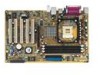
... in 478-pin package coupled with support for buying the ASUS® P4V800-X motherboard! Supporting up to 3.2GHz core frequencies with the VIA® PT800 chipset to enter the world of ASUS quality motherboards! The ASUS P4V800-X motherboard delivers a host of new features and latest technologies...8X slot, Serial ATA support, USB 2.0, and 6channel audio features, the P4V800-X is damaged or missing, contact your affordable vehicle to set a new benchmark for the following items. ASUS P4V800-X motherboard ASUS P4V800-X series support CD UltraDMA 133/100/66 cable 2 x Serial ATA cables ...
... in 478-pin package coupled with support for buying the ASUS® P4V800-X motherboard! Supporting up to 3.2GHz core frequencies with the VIA® PT800 chipset to enter the world of ASUS quality motherboards! The ASUS P4V800-X motherboard delivers a host of new features and latest technologies...8X slot, Serial ATA support, USB 2.0, and 6channel audio features, the P4V800-X is damaged or missing, contact your affordable vehicle to set a new benchmark for the following items. ASUS P4V800-X motherboard ASUS P4V800-X series support CD UltraDMA 133/100/66 cable 2 x Serial ATA cables ...
P4V800-X User Manual
Page 13
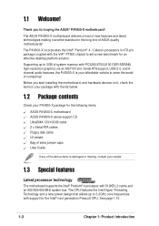
... is enhanced with lower pin count, reduced voltage requirement, up to provide 6-channel audio playback for 5.1 surround sound and over 90dB dynamic range. ASUS P4V800-X motherboard user guide 1-3 Serial ATA technology The motherboard bundles the new Serial ATA technology through the SATA interfaces onboard.... ASUS motherboards now enable users to enjoy this protection feature without the need to create Serial ATA RAID0 and RAID1 configurations using PC3200/2700/...
... is enhanced with lower pin count, reduced voltage requirement, up to provide 6-channel audio playback for 5.1 surround sound and over 90dB dynamic range. ASUS P4V800-X motherboard user guide 1-3 Serial ATA technology The motherboard bundles the new Serial ATA technology through the SATA interfaces onboard.... ASUS motherboards now enable users to enjoy this protection feature without the need to create Serial ATA RAID0 and RAID1 configurations using PC3200/2700/...
P4V800-X User Manual
Page 15
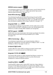
...). 6 IDE connectors. This 4Mb firmware contains the programmable BIOS program. 13 Super I /O functionality. This Low Pin Count (LPC) interface provides the commonly used Super I /O controller. ASUS P4V800-X motherboard user guide 1-5 The power supply must have at 400/ 333/266MHz operation, and 1.5V/0.8V AGP interface that supports AGP 3.0 specification including 8X Fast...
...). 6 IDE connectors. This 4Mb firmware contains the programmable BIOS program. 13 Super I /O functionality. This Low Pin Count (LPC) interface provides the commonly used Super I /O controller. ASUS P4V800-X motherboard user guide 1-5 The power supply must have at 400/ 333/266MHz operation, and 1.5V/0.8V AGP interface that supports AGP 3.0 specification including 8X Fast...
P4V800-X User Manual
Page 17
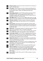
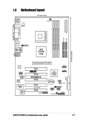
...:Line Out Below:Mic In VIA PT800 Chip REALTEK FP_AUDIO CD AUX Audio Codec Super I/O 4Mbit ROM Accelerated Graphics Port (AGP) SATA1 PCI1 ® PCI2 P4V800-X PCI3 PCI4 SB_PWR1 PCI5 GAME1 VIA VT8237 Chipset SATA2 CR2032 3V Lithium Cell CMOS Power CHASSIS1 CLRTC1 USBPW78 USBPW56 USB78 USB56 CHA_FAN1 PANEL1 FLOPPY...
...:Line Out Below:Mic In VIA PT800 Chip REALTEK FP_AUDIO CD AUX Audio Codec Super I/O 4Mbit ROM Accelerated Graphics Port (AGP) SATA1 PCI1 ® PCI2 P4V800-X PCI3 PCI4 SB_PWR1 PCI5 GAME1 VIA VT8237 Chipset SATA2 CR2032 3V Lithium Cell CMOS Power CHASSIS1 CLRTC1 USBPW78 USBPW56 USB78 USB56 CHA_FAN1 PANEL1 FLOPPY...
P4V800-X User Manual
Page 19
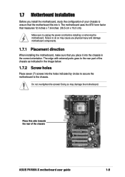
... power cord before installing or removing the motherboard. Failure to do so may damage the motherboard. Place this side towards the rear of the chassis ASUS P4V800-X motherboard user guide 1-9 Doing so may cause you physical injury and damage motherboard components. 1.7.1 Placement direction When installing the motherboard, make sure that you install...
... power cord before installing or removing the motherboard. Failure to do so may damage the motherboard. Place this side towards the rear of the chassis ASUS P4V800-X motherboard user guide 1-9 Doing so may cause you physical injury and damage motherboard components. 1.7.1 Placement direction When installing the motherboard, make sure that you install...
P4V800-X User Manual
Page 21
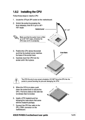
... socket lever. 4. Position the CPU above the socket such that came with the heatsink package. 7. When the CPU is lifted up to secure the CPU. ASUS P4V800-X motherboard user guide 1-11 Unlock the socket by pressing the lever sideways, then lift it up to indicate that the socket lever is in place...
... socket lever. 4. Position the CPU above the socket such that came with the heatsink package. 7. When the CPU is lifted up to secure the CPU. ASUS P4V800-X motherboard user guide 1-11 Unlock the socket by pressing the lever sideways, then lift it up to indicate that the socket lever is in place...
P4V800-X User Manual
Page 23
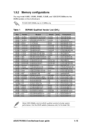
ASUS P4V800-X motherboard user guide 1-13 Visit the ASUS website (www.asus.com) for better system performance. Table 1 DDR400 Qualified Vendor List (QVL) Size Vendor 256MB 256MB 256MB 256MB 512MB 256MB 256MB 512MB 512MB 256MB 256MB 256MB ... NANYA DS NT5DS32M8BT-5T CENTURY SS K4H560838D-TCCC CENTURY DS K4H560838D-TCCC Elixir SS N2DS25680BT-5T Elixir DS N2DS25680BT-5T Obtain DDR DIMMs only from ASUS qualified vendors for the latest QVL. PC3200 DDR DIMMs max to 2 DIMMs only. 1.9.2 Memory configurations You may install 64MB, 128MB, 256MB, 512MB, and 1GB DDR...
ASUS P4V800-X motherboard user guide 1-13 Visit the ASUS website (www.asus.com) for better system performance. Table 1 DDR400 Qualified Vendor List (QVL) Size Vendor 256MB 256MB 256MB 256MB 512MB 256MB 256MB 512MB 512MB 256MB 256MB 256MB ... NANYA DS NT5DS32M8BT-5T CENTURY SS K4H560838D-TCCC CENTURY DS K4H560838D-TCCC Elixir SS N2DS25680BT-5T Elixir DS N2DS25680BT-5T Obtain DDR DIMMs only from ASUS qualified vendors for the latest QVL. PC3200 DDR DIMMs max to 2 DIMMs only. 1.9.2 Memory configurations You may install 64MB, 128MB, 256MB, 512MB, and 1GB DDR...
P4V800-X User Manual
Page 25
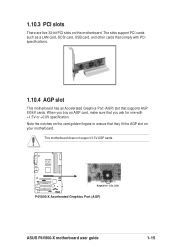
When you ask for 1.5v, 0.8v P4V800-X Accelerated Graphics Port (AGP) ASUS P4V800-X motherboard user guide 1-15 This motherboard does not support 3.3V AGP cards. ® P4V800-X Keyed for one with PCI specifications. 1.10.4 AGP slot This motherboard has an Accelerated Graphics Port (AGP) slot that supports AGP 8X/4X cards. 1.10.3 ...
When you ask for 1.5v, 0.8v P4V800-X Accelerated Graphics Port (AGP) ASUS P4V800-X motherboard user guide 1-15 This motherboard does not support 3.3V AGP cards. ® P4V800-X Keyed for one with PCI specifications. 1.10.4 AGP slot This motherboard has an Accelerated Graphics Port (AGP) slot that supports AGP 8X/4X cards. 1.10.3 ...
P4V800-X User Manual
Page 27
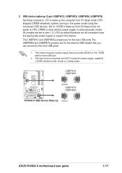
... (Default) +5VSB USBPW78 USBPW56 12 23 +5V P4V800-X USB Device Wake Up (Default) +5VSB ASUS P4V800-X motherboard user guide 1-17 2. The USBPW12 and USBPW34 jumpers are for the rear USB ports.The USBPW56 and USBPW78 jumpers are set to pins 1-2 (+5V) ...
... (Default) +5VSB USBPW78 USBPW56 12 23 +5V P4V800-X USB Device Wake Up (Default) +5VSB ASUS P4V800-X motherboard user guide 1-17 2. The USBPW12 and USBPW34 jumpers are for the rear USB ports.The USBPW56 and USBPW78 jumpers are set to pins 1-2 (+5V) ...
P4V800-X User Manual
Page 29
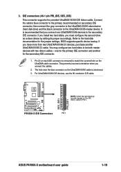
... 20 on each IDE connector is removed to PIN 1. one for the primary IDE connector and another UltraDMA100/66/33 cable. PIN 1 ASUS P4V800-X motherboard user guide 1-19 If you install two hard disks, you connect the cables. 2. It is intentional. 3. This prevents incorrect ...orientation when you must configure the second drive as a slave device by setting its jumper accordingly. P4V800-X P4V800-X IDE Connectors SEC_IDE1 PRI_IDE1 NOTE: Orient the red markings (usually zigzag) on the IDE ribbon cable to match the covered hole on ...
... 20 on each IDE connector is removed to PIN 1. one for the primary IDE connector and another UltraDMA100/66/33 cable. PIN 1 ASUS P4V800-X motherboard user guide 1-19 If you install two hard disks, you connect the cables. 2. It is intentional. 3. This prevents incorrect ...orientation when you must configure the second drive as a slave device by setting its jumper accordingly. P4V800-X P4V800-X IDE Connectors SEC_IDE1 PRI_IDE1 NOTE: Orient the red markings (usually zigzag) on the IDE ribbon cable to match the covered hole on ...
P4V800-X User Manual
Page 31
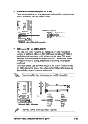
... high resolution cameras, scanners, and printers. Internal audio connectors (4-pin CD1, AUX1) These connectors allow you can use the USB 2.0 capability. ASUS P4V800-X motherboard user guide USB+5V USB_P5USB_P5+ GND 1-21 USB header (10-1 pin USB56, USB78) If the USB ports on USB 1.1 allows ...module has two USB 2.0 ports that supports up to this header. USB+5V USB_P6USB_P6+ GND NC USB+5V USB_P8USB_P8+ GND NC ® P4V800-X P4V800-X USB 2.0 Header USB78 1 USB56 1 USB+5V USB_P7USB_P7+ GND The USB2.0/GAME module is purchased separately. This speed advantage over the conventional...
... high resolution cameras, scanners, and printers. Internal audio connectors (4-pin CD1, AUX1) These connectors allow you can use the USB 2.0 capability. ASUS P4V800-X motherboard user guide USB+5V USB_P5USB_P5+ GND 1-21 USB header (10-1 pin USB56, USB78) If the USB ports on USB 1.1 allows ...module has two USB 2.0 ports that supports up to this header. USB+5V USB_P6USB_P6+ GND NC USB+5V USB_P8USB_P8+ GND NC ® P4V800-X P4V800-X USB 2.0 Header USB78 1 USB56 1 USB+5V USB_P7USB_P7+ GND The USB2.0/GAME module is purchased separately. This speed advantage over the conventional...
P4V800-X User Manual
Page 33
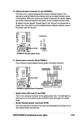
...By default, the pins labeled "Chassis Signal" and "Ground" are shorted with intrusion detection feature. ExtSMI# Ground PWR Ground Reset Ground P4V800-X IDE_LED SMI Lead Reset SW ATX Power Switch* * Requires an ATX power supply. The LED lights up when you to record a chassis intrusion...If you remove any chassis component, the sensor triggers and sends a high-level signal to this lead to hear system beeps and warnings. ASUS P4V800-X motherboard user guide 1-23 Power LED Speaker Connector PLED+ PLED+5V Ground Ground Speaker IDE_LED+ IDE_LED- When you wish to the system...
...By default, the pins labeled "Chassis Signal" and "Ground" are shorted with intrusion detection feature. ExtSMI# Ground PWR Ground Reset Ground P4V800-X IDE_LED SMI Lead Reset SW ATX Power Switch* * Requires an ATX power supply. The LED lights up when you to record a chassis intrusion...If you remove any chassis component, the sensor triggers and sends a high-level signal to this lead to hear system beeps and warnings. ASUS P4V800-X motherboard user guide 1-23 Power LED Speaker Connector PLED+ PLED+5V Ground Ground Speaker IDE_LED+ IDE_LED- When you wish to the system...
P4V800-X User Manual
Page 37
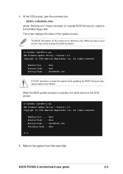
... "filename.rom" means the latest (or original) BIOS file that you see on the screen is complete, the utility returns to the bootable floppy disk. ASUS P4V800-X motherboard user guide 2-3 4.
... "filename.rom" means the latest (or original) BIOS file that you see on the screen is complete, the utility returns to the bootable floppy disk. ASUS P4V800-X motherboard user guide 2-3 4.
P4V800-X User Manual
Page 39
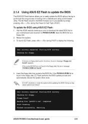
...you to easily update the BIOS without having to go through the long process of booting from a diskette and using ASUS EZ Flash: 1. Checking for floppy... Doing so may cause system boot failure! Start flashing... Flashed successfully. Save ...If the correct BIOS file is accessible by simply pressing + during POST to P4V800-X.ROM. Visit the ASUS website (www.asus.com) to a floppy disk. 2. Completed. Rebooting. ASUS P4V800-X motherboard user guide 2-5 Reading file "p4v800-x.rom". Starting BIOS recovery... Insert the floppy disk that contains the BIOS file....
...you to easily update the BIOS without having to go through the long process of booting from a diskette and using ASUS EZ Flash: 1. Checking for floppy... Doing so may cause system boot failure! Start flashing... Flashed successfully. Save ...If the correct BIOS file is accessible by simply pressing + during POST to P4V800-X.ROM. Visit the ASUS website (www.asus.com) to a floppy disk. 2. Completed. Rebooting. ASUS P4V800-X motherboard user guide 2-5 Reading file "p4v800-x.rom". Starting BIOS recovery... Insert the floppy disk that contains the BIOS file....
P4V800-X User Manual
Page 41
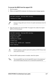
... motherboard. Bad BIOS checksum. Bad BIOS checksum. When the BIOS update process is detected, the following screen message appears. Checking for floppy... Visit the ASUS website (www.asus.com) to download the latest BIOS file. When a corrupted BIOS is complete, reboot the system. If there is no floppy disk found in the... recovery... Floppy not found . Start flashing... DO NOT shutdown or reset the system while updating the BIOS! The recovered BIOS may cause system boot failure! 4. ASUS P4V800-X motherboard user guide 2-7
... motherboard. Bad BIOS checksum. Bad BIOS checksum. When the BIOS update process is detected, the following screen message appears. Checking for floppy... Visit the ASUS website (www.asus.com) to download the latest BIOS file. When a corrupted BIOS is complete, reboot the system. If there is no floppy disk found in the... recovery... Floppy not found . Start flashing... DO NOT shutdown or reset the system while updating the BIOS! The recovered BIOS may cause system boot failure! 4. ASUS P4V800-X motherboard user guide 2-7
P4V800-X User Manual
Page 43
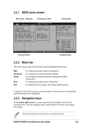
... Diskette A [11:10:19] [Thu 05/27/2003] [1.44M, 3.5 in] Primary IDE Master Primary IDE Slave Secondary IDE Master Secondary IDE Slave System Information :[ST320413A] :[ASUS CD-S340] :[Not Detected] :[Not Detected] Sub-menu items Use [ENTER], [TAB] or [SHIFT-TAB] to select items in the menu and change the settings... corner of the navigation keys differ from one screen to configure system time. Some of a menu screen are the navigation keys for that particular menu. ASUS P4V800-X motherboard user guide 2-9 Use [+] or [-] to another. Select Screen Select Item +-
... Diskette A [11:10:19] [Thu 05/27/2003] [1.44M, 3.5 in] Primary IDE Master Primary IDE Slave Secondary IDE Master Secondary IDE Slave System Information :[ST320413A] :[ASUS CD-S340] :[Not Detected] :[Not Detected] Sub-menu items Use [ENTER], [TAB] or [SHIFT-TAB] to select items in the menu and change the settings... corner of the navigation keys differ from one screen to configure system time. Some of a menu screen are the navigation keys for that particular menu. ASUS P4V800-X motherboard user guide 2-9 Use [+] or [-] to another. Select Screen Select Item +-
P4V800-X User Manual
Page 45
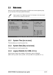
... [-] to select a field. System Time System Date Legacy Diskette A [11:10:19] [Thu 05/27/2003] [1.44M, 3.5 in .] ASUS P4V800-X motherboard user guide 2-11 Select Screen Select Item +- Change Field Tab Select Field F1 General Help F10 Save and Exit ESC Exit 2.3.1 System Time... , 3.5 in.] [1.44M, 3.5 in.] [2.88M, 3.5 in ] Primary IDE Master Primary IDE Slave Secondary IDE Master Secondary IDE Slave System Information :[ST320413A] :[ASUS CD-S340] :[Not Detected] :[Not Detected] Use [ENTER], [TAB] or [SHIFT-TAB] to configure system time. Refer to section "2.2.1 BIOS menu screen" for...
... [-] to select a field. System Time System Date Legacy Diskette A [11:10:19] [Thu 05/27/2003] [1.44M, 3.5 in .] ASUS P4V800-X motherboard user guide 2-11 Select Screen Select Item +- Change Field Tab Select Field F1 General Help F10 Save and Exit ESC Exit 2.3.1 System Time... , 3.5 in.] [1.44M, 3.5 in.] [2.88M, 3.5 in ] Primary IDE Master Primary IDE Slave Secondary IDE Master Secondary IDE Slave System Information :[ST320413A] :[ASUS CD-S340] :[Not Detected] :[Not Detected] Use [ENTER], [TAB] or [SHIFT-TAB] to configure system time. Refer to section "2.2.1 BIOS menu screen" for...
P4V800-X User Manual
Page 47
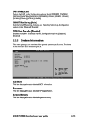
System Memory This item displays the auto-detected system memory. ASUS P4V800-X motherboard user guide 2-13 The items in this menu are auto-detected by BIOS. Change Option F1 General Help F10 Save and Exit ESC Exit ...
System Memory This item displays the auto-detected system memory. ASUS P4V800-X motherboard user guide 2-13 The items in this menu are auto-detected by BIOS. Change Option F1 General Help F10 Save and Exit ESC Exit ...
P4V800-X User Manual
Page 49
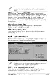
... the configuration options. Select an item then press Enter to adjust the CPU frequency. Configuration options: [Disabled] [USB 2 Ports] [USB 4 Ports] [USB 6 Ports] [USB 8 Ports] ASUS P4V800-X motherboard user guide 2-15 The bus frequency (external frequency) multiplied by the clock generator to the system bus and PCI bus. The value of this...
... the configuration options. Select an item then press Enter to adjust the CPU frequency. Configuration options: [Disabled] [USB 2 Ports] [USB 4 Ports] [USB 6 Ports] [USB 8 Ports] ASUS P4V800-X motherboard user guide 2-15 The bus frequency (external frequency) multiplied by the clock generator to the system bus and PCI bus. The value of this...
P4V800-X User Manual
Page 51
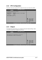
... Select Item +- Select an item then press Enter to change the advanced chipset settings. Change Option F1 General Help F10 Save and Exit ESC Exit ASUS P4V800-X motherboard user guide 2-17 2.4.3 CPU Configuration The items in this menu show the CPU-related information auto-detected by BIOS.
... Select Item +- Select an item then press Enter to change the advanced chipset settings. Change Option F1 General Help F10 Save and Exit ESC Exit ASUS P4V800-X motherboard user guide 2-17 2.4.3 CPU Configuration The items in this menu show the CPU-related information auto-detected by BIOS.


