Motherboard DIY Troubleshooting Guide
Page 53
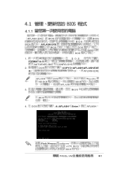
FORMAT A:/S AUTOEXEC.BAT 2. A:\ DOS DOS CONFIG.SYS COPY D:\AFLASH\AFLASH.EXE D AFLASH.EXE AFLASH MS-DOS DOS AFLASH BIOS Winodws 3. BIOS BIOS 4. DOS A:\AFLASH Enter AFLASH Flash Memory unknown ACPI BIOS BIOS P4SGL-VM 4-1 4.1.1 AFLASH.EXE BIOS BIOS AFLASH.EXE BIOS BIOS BIOS DOS DOS BIOS 1.
FORMAT A:/S AUTOEXEC.BAT 2. A:\ DOS DOS CONFIG.SYS COPY D:\AFLASH\AFLASH.EXE D AFLASH.EXE AFLASH MS-DOS DOS AFLASH BIOS Winodws 3. BIOS BIOS 4. DOS A:\AFLASH Enter AFLASH Flash Memory unknown ACPI BIOS BIOS P4SGL-VM 4-1 4.1.1 AFLASH.EXE BIOS BIOS AFLASH.EXE BIOS BIOS BIOS DOS DOS BIOS 1.
Motherboard DIY Troubleshooting Guide
Page 57
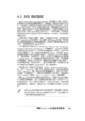
DEL BIOS P4SGL-VM 4-5 CTRL - BIOS Basic Input and Output System BIOS BIOS BIOS RUN SETUP BIOS BIOS EEPROM Programmable Read-Only Memory EEPROM Electrical Erasable BIOS BIOS BIOS BIOS CMOS RAM BIOS DELETE DELETE POST Power-On Self Test RESET BIOS ALT -
DEL BIOS P4SGL-VM 4-5 CTRL - BIOS Basic Input and Output System BIOS BIOS BIOS RUN SETUP BIOS BIOS EEPROM Programmable Read-Only Memory EEPROM Electrical Erasable BIOS BIOS BIOS BIOS CMOS RAM BIOS DELETE DELETE POST Power-On Self Test RESET BIOS ALT -
Motherboard DIY Troubleshooting Guide
Page 68
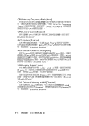
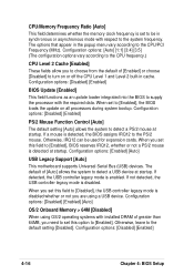
CPU/Memory Frequency Ratio [Auto] MHz CPU CPU/PCI Frequency [Auto] [1:1] [3:4][3:5] CPU Level 2 Cache [Enabled] CPU [Disabled] [Enabled] BIOS Update [Enabled] BIOS CPU BIOS CPU [Disabled] [Enabled] PS/2 Mouse Function Control [Auto] [Auto] PS/2 BIOS IRQ 12 PS/2 [Enabled] PS/2 BIOS IRQ 12 [Enabled] [Auto] IRQ 12 PS/2 USB Legacy Support [Auto] [Auto] USB USB USB 1.1 USB ] [Enabled] [Auto] [Disabled] USB USB [Disabled OS/2 Onboard Memory > 64M [Disabled] OS/2 [Enabled] [Disabled] [Enabled] 64MB [Disabled] 4-16 BIOS
CPU/Memory Frequency Ratio [Auto] MHz CPU CPU/PCI Frequency [Auto] [1:1] [3:4][3:5] CPU Level 2 Cache [Enabled] CPU [Disabled] [Enabled] BIOS Update [Enabled] BIOS CPU BIOS CPU [Disabled] [Enabled] PS/2 Mouse Function Control [Auto] [Auto] PS/2 BIOS IRQ 12 PS/2 [Enabled] PS/2 BIOS IRQ 12 [Enabled] [Auto] IRQ 12 PS/2 USB Legacy Support [Auto] [Auto] USB USB USB 1.1 USB ] [Enabled] [Auto] [Disabled] USB USB [Disabled OS/2 Onboard Memory > 64M [Disabled] OS/2 [Enabled] [Disabled] [Enabled] 64MB [Disabled] 4-16 BIOS

Motherboard DIY Troubleshooting Guide
Page 69
4.4.1 Chip Configuration SDRAM Configuration [By SPD] 2 SPD Serial Presence Detect EEPROM memory type voltage module banks 5 [By SPD] 2 5 size speed [User Define] [By SPD] SDRAM CAS Latency [2.5T] SDRAM SDRAM CAS Latency [User Defined] SDRAM RAS to CAS Delay [3T] SDRAM SDRAM Configuration / The SDRAM RAS to CAS Delay Configuration [User Defined] SDRAM P4SGL-VM 4-17
4.4.1 Chip Configuration SDRAM Configuration [By SPD] 2 SPD Serial Presence Detect EEPROM memory type voltage module banks 5 [By SPD] 2 5 size speed [User Define] [By SPD] SDRAM CAS Latency [2.5T] SDRAM SDRAM CAS Latency [User Defined] SDRAM RAS to CAS Delay [3T] SDRAM SDRAM Configuration / The SDRAM RAS to CAS Delay Configuration [User Defined] SDRAM P4SGL-VM 4-17
Motherboard DIY Troubleshooting Guide
Page 70
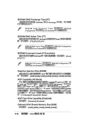
.../4X AGP 266MB [2X Mode] AGP 4X AGP 533MB [1X Mode] [2X Mode] [4X Mode] AGP Fast Write Capability [Disabled] [Disabled] [Enabled] Onboard VGA Shared Memory Size [32M] [4MB] [8MB] [16MB] [32MB] [64MB] 4-18 BIOS
.../4X AGP 266MB [2X Mode] AGP 4X AGP 533MB [1X Mode] [2X Mode] [4X Mode] AGP Fast Write Capability [Disabled] [Disabled] [Enabled] Onboard VGA Shared Memory Size [32M] [4MB] [8MB] [16MB] [32MB] [64MB] 4-18 BIOS

Motherboard DIY Troubleshooting Guide
Page 71
Video Memory Cache Mode [UC] USWC uncacheable, speculative write combining [UC] [UC] [USWC] Memory Hole At 15M-16M [Disabled] 15M-16M ISA [Disabled] [Enabled] 16MB PCI 2.1 Support [Enabled] 2.1 PCI [Disabled] PCI 2.1 PCI [Enabled] [Enabled] [Disabled] Onboard PCI IDE Enabled [Both] Primary IDE Secondary IDE [Both] [Primary] [Secondary] [Disabled] IDE Bus Master Support [Disabled] [Disabled] IDE Bus Master [Enabled] [Disabled] P4SGL-VM 4-19
Video Memory Cache Mode [UC] USWC uncacheable, speculative write combining [UC] [UC] [USWC] Memory Hole At 15M-16M [Disabled] 15M-16M ISA [Disabled] [Enabled] 16MB PCI 2.1 Support [Enabled] 2.1 PCI [Disabled] PCI 2.1 PCI [Enabled] [Enabled] [Disabled] Onboard PCI IDE Enabled [Both] Primary IDE Secondary IDE [Both] [Primary] [Secondary] [Disabled] IDE Bus Master Support [Disabled] [Disabled] IDE Bus Master [Enabled] [Disabled] P4SGL-VM 4-19

P4SGL-VM User Manual
Page 3
...About this guide viii How this guide is organized viii Conventions used in this guide ix Where to find more information ix ASUS contact information x Chapter 1: Product introduction 1-1 1.1 Welcome 1-1 1.2 Package contents 1-1 1.3 Special features 1-2 1.3.1 Product highlights... 2-4 2.4.2 Installing the CPU 2-5 2.4.3 Installing the heatsink and fan 2-7 2.4.4 Connecting the CPU fan cable 2-9 2.5 System memory 2-10 2.5.1 Overview 2-10 2.5.2 Memory configurations 2-11 2.5.3 Installing a DIMM 2-12 2.5.4 Removing a DIMM 2-13 2.6 Expansion slots 2-14 2.6.1 Installing an expansion ...
...About this guide viii How this guide is organized viii Conventions used in this guide ix Where to find more information ix ASUS contact information x Chapter 1: Product introduction 1-1 1.1 Welcome 1-1 1.2 Package contents 1-1 1.3 Special features 1-2 1.3.1 Product highlights... 2-4 2.4.2 Installing the CPU 2-5 2.4.3 Installing the heatsink and fan 2-7 2.4.4 Connecting the CPU fan cable 2-9 2.5 System memory 2-10 2.5.1 Overview 2-10 2.5.2 Memory configurations 2-11 2.5.3 Installing a DIMM 2-12 2.5.4 Removing a DIMM 2-13 2.6 Expansion slots 2-14 2.6.1 Installing an expansion ...
P4SGL-VM User Manual
Page 13
... floppy drive Bag of extra jumper caps User Guide If any of system memory with the SiS 650GL chipset to get ahead in the long line of power computing! Supporting up to 2GB of the above items is your retailer. ASUS P4SGL-VM motherboard user guide 1-1 Before you for an effective desktop platform solution.
... floppy drive Bag of extra jumper caps User Guide If any of system memory with the SiS 650GL chipset to get ahead in the long line of power computing! Supporting up to 2GB of the above items is your retailer. ASUS P4SGL-VM motherboard user guide 1-1 Before you for an effective desktop platform solution.

P4SGL-VM User Manual
Page 14
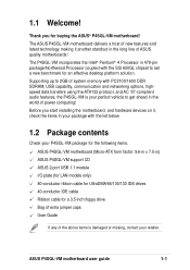
...surround sound and enhanced 3D audio while playing DVDs and computer games. See page 2-24. 1.3 Special features 1.3.1 Product highlights Latest processor technology The P4SGL-VM motherboard supports the latest Intel Pentium 4 478/ Northwood Processor, also known as P4, via a 478-pin surface mount ZIF socket. Digital audio ... a 2.0GHz frequency, while the Northwood processor uses the 0.13 micron processor core with 512KB L2 cache for up to 2GB of system memory using PC2100/ 1600 DDR DIMMs to support AC'97 compliant audio devices. Onboard LAN (on audio models only) On audio models, a ...
...surround sound and enhanced 3D audio while playing DVDs and computer games. See page 2-24. 1.3 Special features 1.3.1 Product highlights Latest processor technology The P4SGL-VM motherboard supports the latest Intel Pentium 4 478/ Northwood Processor, also known as P4, via a 478-pin surface mount ZIF socket. Digital audio ... a 2.0GHz frequency, while the Northwood processor uses the 0.13 micron processor core with 512KB L2 cache for up to 2GB of system memory using PC2100/ 1600 DDR DIMMs to support AC'97 compliant audio devices. Onboard LAN (on audio models only) On audio models, a ...
P4SGL-VM User Manual
Page 18
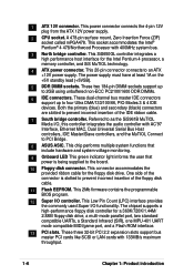
... up to PCI Bridge. 8 ASUS ASIC. Both the primary (blue) and secondary (black) connectors are slotted to an ATX +12V power supply. This 2Mb firmware contains the programmable BIOS program. 12 Super I /O functionality. The chipset supports a high-performance floppy disk controller for the Intel Pentium 4 processor, a memory controller, and SiS MuTIOL technology...
... up to PCI Bridge. 8 ASUS ASIC. Both the primary (blue) and secondary (black) connectors are slotted to an ATX +12V power supply. This 2Mb firmware contains the programmable BIOS program. 12 Super I /O functionality. The chipset supports a high-performance floppy disk controller for the Intel Pentium 4 processor, a memory controller, and SiS MuTIOL technology...
P4SGL-VM User Manual
Page 24
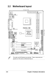
... In CD1 AUX1 Audio Codec FPAUDIO1 ITE 8707F Super I/O 2Mbit Flash BIOS SMARTCON1 FLOPPY1 P4SGL-VM ATX12V1 SiS650GL HOST/ Memory Controller 01 23 PCI Slot 1 ® PCI Slot 2 BATTERY1 PCI Slot 3 USB2 IR1 USBV2 SiS961B MuTLOL Media I/0 CLRTC ASUS Mozart SIRQ1 HPANEL1 SPDIF1 IDELED1 The audio and LAN features are grayed out in the...
... In CD1 AUX1 Audio Codec FPAUDIO1 ITE 8707F Super I/O 2Mbit Flash BIOS SMARTCON1 FLOPPY1 P4SGL-VM ATX12V1 SiS650GL HOST/ Memory Controller 01 23 PCI Slot 1 ® PCI Slot 2 BATTERY1 PCI Slot 3 USB2 IR1 USBV2 SiS961B MuTLOL Media I/0 CLRTC ASUS Mozart SIRQ1 HPANEL1 SPDIF1 IDELED1 The audio and LAN features are grayed out in the...

P4SGL-VM User Manual
Page 32
... so that it has a 184-pin footprint compared to the 168-pin of SDR memory. DO NOT force a DIMM into a socket to 2GB system memory using 184-pin unbuffered non-ECC PC2100/1600 DIMMs. P4SGL-VM ® P4SGL-VM 184-Pin DDR DIMM Sockets 104 Pins 80 Pins A DDR DIMM is keyed with ...two Double Data Rate (DDR) Dual Inline Memory Module (DIMM) sockets. DDR memory however, has the ability to perform two...
... so that it has a 184-pin footprint compared to the 168-pin of SDR memory. DO NOT force a DIMM into a socket to 2GB system memory using 184-pin unbuffered non-ECC PC2100/1600 DIMMs. P4SGL-VM ® P4SGL-VM 184-Pin DDR DIMM Sockets 104 Pins 80 Pins A DDR DIMM is keyed with ...two Double Data Rate (DDR) Dual Inline Memory Module (DIMM) sockets. DDR memory however, has the ability to perform two...

P4SGL-VM User Manual
Page 33
Use the following combinations to install DDR DIMMs. DIMM Location 184-pin DDR DIMM Total Memory Socket 1 (Rows 0&1) 64MB, 128MB, 256MB, 512MB, 1GB x1 = Socket 2 (Rows 2&3) 64MB, 128MB, 256MB, 512MB, 1GB x1 = Total system memory (Max. 2GB) = ASUS P4SGL-VM motherboard user guide 2-11 2.5.2 Memory configurations You may install any DDR DIMMs with 64MB, 128MB, 256MB, 512MB, and 1GB densities into the two DIMM sockets.
Use the following combinations to install DDR DIMMs. DIMM Location 184-pin DDR DIMM Total Memory Socket 1 (Rows 0&1) 64MB, 128MB, 256MB, 512MB, 1GB x1 = Socket 2 (Rows 2&3) 64MB, 128MB, 256MB, 512MB, 1GB x1 = Total system memory (Max. 2GB) = ASUS P4SGL-VM motherboard user guide 2-11 2.5.2 Memory configurations You may install any DDR DIMMs with 64MB, 128MB, 256MB, 512MB, and 1GB densities into the two DIMM sockets.

P4SGL-VM User Manual
Page 40
P4SGL-VM ® P4SGL-VM Clear RTC RAM Setting Short solder points to clear the Real Time Clock (RTC) RAM in CMOS, that include system setup information such as system ... unplug the power cord. 2. Short the solder points. 4. 2. Remove the battery. 3. Plug the power cord and turn ON the computer. 6. You can clear the CMOS memory of date, time, and system setup parameters by the onboard button cell battery. Hold down the key during the boot process and enter BIOS setup...
P4SGL-VM ® P4SGL-VM Clear RTC RAM Setting Short solder points to clear the Real Time Clock (RTC) RAM in CMOS, that include system setup information such as system ... unplug the power cord. 2. Short the solder points. 4. 2. Remove the battery. 3. Plug the power cord and turn ON the computer. 6. You can clear the CMOS memory of date, time, and system setup parameters by the onboard button cell battery. Hold down the key during the boot process and enter BIOS setup...
P4SGL-VM User Manual
Page 53
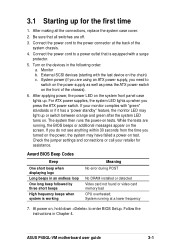
...off. 3. Be sure that is working Meaning No error during POST No DRAM installed or detected Video card not found or video card memory bad CPU overheated; Turn on the devices in an endless loop One long beep followed by three short beeps High frequency beeps when ... all the connections, replace the system case cover. 2. Monitor b. After applying power, the power LED on . If your retailer for the first time 1. ASUS P4SGL-VM motherboard user guide 3-1 External SCSI devices (starting with "green" standards or if it has a "power standby" feature, the monitor LED may have failed a...
...off. 3. Be sure that is working Meaning No error during POST No DRAM installed or detected Video card not found or video card memory bad CPU overheated; Turn on the devices in an endless loop One long beep followed by three short beeps High frequency beeps when ... all the connections, replace the system case cover. 2. Monitor b. After applying power, the power LED on . If your retailer for the first time 1. ASUS P4SGL-VM motherboard user guide 3-1 External SCSI devices (starting with "green" standards or if it has a "power standby" feature, the monitor LED may have failed a...
P4SGL-VM User Manual
Page 57
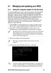
... utility that you save a copy of the original motherboard BIOS along with certain memory drivers that you reboot using a floppy disk. 3. BIOS setup must specify "Floppy" as the first item in DOS mode. ASUS P4SGL-VM motherboard user guide 4-1 DO NOT copy AUTOEXEC.BAT and CONFIG.SYS to create ...a bootable system disk. AFLASH.EXE is recommended that updates the BIOS by the Flash Memory Writer utility. This file works only in the boot sequence...
... utility that you save a copy of the original motherboard BIOS along with certain memory drivers that you reboot using a floppy disk. 3. BIOS setup must specify "Floppy" as the first item in DOS mode. ASUS P4SGL-VM motherboard user guide 4-1 DO NOT copy AUTOEXEC.BAT and CONFIG.SYS to create ...a bootable system disk. AFLASH.EXE is recommended that updates the BIOS by the Flash Memory Writer utility. This file works only in the boot sequence...
P4SGL-VM User Manual
Page 60
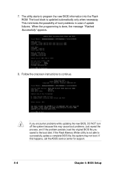
... file you encounter problems while updating the new BIOS, DO NOT turn off the system because this happens, call the ASUS service center for support. 4-4 Chapter 4: BIOS Setup If the Flash Memory Writer utility is not able to the boot disk. This minimizes the possibility of boot problems in case of update...
... file you encounter problems while updating the new BIOS, DO NOT turn off the system because this happens, call the ASUS service center for support. 4-4 Chapter 4: BIOS Setup If the Flash Memory Writer utility is not able to the boot disk. This minimizes the possibility of boot problems in case of update...

P4SGL-VM User Manual
Page 70
... [English] This field displays the BIOS language version. Configuration options: [All Errors] [No Error] [All but Keyboard] [All but Disk] [All but Disk/Keyboard] Installed Memory [XXX MB] This field automatically displays the amount of errors that will cause the system to the BIOS Setup menus. Main menu items continued... To..., type the password again and press . The same dialog box as above appears. Press . Halt On [All Errors] This field specifies the types of conventional memory detected by the system during system startup.
... [English] This field displays the BIOS language version. Configuration options: [All Errors] [No Error] [All but Keyboard] [All but Disk] [All but Disk/Keyboard] Installed Memory [XXX MB] This field automatically displays the amount of errors that will cause the system to the BIOS Setup menus. Main menu items continued... To..., type the password again and press . The same dialog box as above appears. Press . Halt On [All Errors] This field specifies the types of conventional memory detected by the system during system startup.
P4SGL-VM User Manual
Page 72
...supply the processor with the required data. If a mouse is set to be used for expansion cards. CPU/Memory Frequency Ratio [Auto] This field determines whether the memory clock frequency is detected, the BIOS assigns IRQ12 to the PS/2 mouse. When you set to the CPU...choose from the default of [Enabled] or choose [Disabled] to detect a USB device at startup. Configuration options: [Disabled] [Enabled] [Auto] OS/2 Onboard Memory > 64M [Disabled] When using a USB device. When set this field to [Enabled], BIOS reserves IRQ12, whether or not a PS/2 mouse is disabled. ...
...supply the processor with the required data. If a mouse is set to be used for expansion cards. CPU/Memory Frequency Ratio [Auto] This field determines whether the memory clock frequency is detected, the BIOS assigns IRQ12 to the PS/2 mouse. When you set to the CPU...choose from the default of [Enabled] or choose [Disabled] to detect a USB device at startup. Configuration options: [Disabled] [Enabled] [Auto] OS/2 Onboard Memory > 64M [Disabled] When using a USB device. When set this field to [Enabled], BIOS reserves IRQ12, whether or not a PS/2 mouse is disabled. ...

P4SGL-VM User Manual
Page 73
The SDRAM CAS Latency parameter appears only when you set the SDRAM Configuration to [User Defined]. The EEPROM on the memory modules that you are using. The SDRAM RAS to CAS Delay parameter appears only when you set the SDRAM Configuration to [User Defined]....the module, such as memory type, size, speed, voltage interface, and module banks. Configuration options: [User Defined] [By SPD] SDRAM CAS Latency [2.5T] This item controls the latency between the SDRAM active command and the read command and the time the data actually becomes available. ASUS P4SGL-VM motherboard user guide 4-...
The SDRAM CAS Latency parameter appears only when you set the SDRAM Configuration to [User Defined]. The EEPROM on the memory modules that you are using. The SDRAM RAS to CAS Delay parameter appears only when you set the SDRAM Configuration to [User Defined]....the module, such as memory type, size, speed, voltage interface, and module banks. Configuration options: [User Defined] [By SPD] SDRAM CAS Latency [2.5T] This item controls the latency between the SDRAM active command and the read command and the time the data actually becomes available. ASUS P4SGL-VM motherboard user guide 4-...


