
P4SGL-MX User Manual
Page 14
... This onboard LED lights up to prevent incorrect insertion of the IDE ribbon cable. 8 AGP Slot. This 9-pin connector connects to set the CPU external frequency. 3 CPU Sockets. One side of the connector is a standby power on the +5V standby lead (+5VSB). 6 DDR DIMM Sockets. A 478-pin ...® Pentium® 4 P478 Willamette & Northwood Processor with 2.1GBytes/sec of core frequency. 4 NorthBridge Controller. These dual-channel bus master IDE connectors support up if there is slotted to four Ultra DMA133/100/66, PIO Modes 3 & 4 IDE devices. This LED acts as a reminder to an ATX...
... This onboard LED lights up to prevent incorrect insertion of the IDE ribbon cable. 8 AGP Slot. This 9-pin connector connects to set the CPU external frequency. 3 CPU Sockets. One side of the connector is a standby power on the +5V standby lead (+5VSB). 6 DDR DIMM Sockets. A 478-pin ...® Pentium® 4 P478 Willamette & Northwood Processor with 2.1GBytes/sec of core frequency. 4 NorthBridge Controller. These dual-channel bus master IDE connectors support up if there is slotted to four Ultra DMA133/100/66, PIO Modes 3 & 4 IDE devices. This LED acts as a reminder to an ATX...

P4SGL-MX User Manual
Page 21
Both jumpers are set to pins 1-2 (+5V) by default because not all computers have the appropriate power supply to support this feature. The total current consumed must NOT exceed the power supply capability (+5VSB) whether under normal condition or...header that can connect to CPU, DRAM in slow refresh, power supply in reduced power mode). The USBPWR12 jumper is for the rear USB port. 2. P4SGL-MX ® USBPWR_12 2 1 +5V (Default) 3 2 +5VSB USBPWR_34 USBPWR_56 12 23 +5V P4SGL-MX USB Device Wake Up (Default) +5VSB ASUS P4SGL-MX Motherboard 1-11 This feature ...
Both jumpers are set to pins 1-2 (+5V) by default because not all computers have the appropriate power supply to support this feature. The total current consumed must NOT exceed the power supply capability (+5VSB) whether under normal condition or...header that can connect to CPU, DRAM in slow refresh, power supply in reduced power mode). The USBPWR12 jumper is for the rear USB port. 2. P4SGL-MX ® USBPWR_12 2 1 +5V (Default) 3 2 +5VSB USBPWR_34 USBPWR_56 12 23 +5V P4SGL-MX USB Device Wake Up (Default) +5VSB ASUS P4SGL-MX Motherboard 1-11 This feature ...
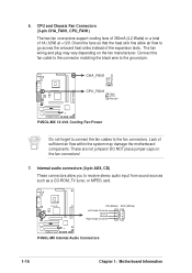
P4SGL-MX User Manual
Page 26
... P4SGL-MX 12-Volt Cooling Fan Power Do not forget to connect the fan cables to receive stereo audio input from sound sources such as a CD-ROM, TV tuner, or MPEG card. Internal audio connectors (4-pin AUX, CD) These connectors allow air flow to the ground pin. 6. CPU and... Chassis Fan Connectors (3-pin CHA_FAN1, CPU_FAN1) The two fan connectors support cooling fans of 350mA (4.2 Watts) or a total of the expansion slots. These are not jumpers! Orient the fans...
... P4SGL-MX 12-Volt Cooling Fan Power Do not forget to connect the fan cables to receive stereo audio input from sound sources such as a CD-ROM, TV tuner, or MPEG card. Internal audio connectors (4-pin AUX, CD) These connectors allow air flow to the ground pin. 6. CPU and... Chassis Fan Connectors (3-pin CHA_FAN1, CPU_FAN1) The two fan connectors support cooling fans of 350mA (4.2 Watts) or a total of the expansion slots. These are not jumpers! Orient the fans...

P4SGL-MX User Manual
Page 46
...Port 1 and Serial Port 2 must have different addresses. The default setting [R/W] allows both . Configuration options: [COM Port] [IR] ASUS P4SGL-MX Motherboard 2-17 This process normally consumes about 50-60 PCI clocks without PCI delayed transaction. UART2 Use As [COM Port] This field ...Configuration Floppy Disk Access Control [R/W] When set to [Enabled], this feature frees the PCI bus when the CPU is accessing 8-bit ISA cards. Configuration options: [Enabled] [Disabled] PCI 2.1 Support [Enabled] This field enables or disables the PCI 2.1 features. Memory Hole At 15M-16M [Disabled]...
...Port 1 and Serial Port 2 must have different addresses. The default setting [R/W] allows both . Configuration options: [COM Port] [IR] ASUS P4SGL-MX Motherboard 2-17 This process normally consumes about 50-60 PCI clocks without PCI delayed transaction. UART2 Use As [COM Port] This field ...Configuration Floppy Disk Access Control [R/W] When set to [Enabled], this feature frees the PCI bus when the CPU is accessing 8-bit ISA cards. Configuration options: [Enabled] [Disabled] PCI 2.1 Support [Enabled] This field enables or disables the PCI 2.1 features. Memory Hole At 15M-16M [Disabled]...

P4SGL-MX User Manual
Page 58
...speed, CPU temperature, and system voltages, and alerts you on the lower right corner of two screens. Microsoft Direct X 8.1 Driver This item installs the Microsoft V8.1 driver. ASUS Update This item installs the ASUS Update. ...the Right Arrow on a specific item then follow the installation wizard to display the second menu screen. ASUS P4SGL-MX Motherboard 3-3 SiS 650/651 Display Driver Click this motherboard. To return to install the display driver ... operating condition. 3.2.2 Software and drivers installation menus The support CD menu is for the SiS 650/651 chipset.
...speed, CPU temperature, and system voltages, and alerts you on the lower right corner of two screens. Microsoft Direct X 8.1 Driver This item installs the Microsoft V8.1 driver. ASUS Update This item installs the ASUS Update. ...the Right Arrow on a specific item then follow the installation wizard to display the second menu screen. ASUS P4SGL-MX Motherboard 3-3 SiS 650/651 Display Driver Click this motherboard. To return to install the display driver ... operating condition. 3.2.2 Software and drivers installation menus The support CD menu is for the SiS 650/651 chipset.


