
P4SE User Manual
Page 11
Motherboard Info ASUS P4SE Motherboard 1-1 Chapter 1 This chapter gives information about the ASUS P4SE motherboard that came with the system.This chapter includes the motherboard layout, jumper settings, and connector locations.
Motherboard Info ASUS P4SE Motherboard 1-1 Chapter 1 This chapter gives information about the ASUS P4SE motherboard that came with the system.This chapter includes the motherboard layout, jumper settings, and connector locations.

P4SE User Manual
Page 12
... cable for Ultra 33 IDE drives Ribbon cable for a 3.5-inch floppy drive Bag of extra jumper caps User Guide 1-2 Thank you for the following items. ASUS P4SE motherboard ATX form factor: 12 in x 8.6 in the long line of PC 2700 / 2100 / 1600 DDR (Note: PC2700 max. to 3GB of system memory... of ASUS quality motherboards! The P4SE incorporates the Intel® Pentium® 4 Processor in 478-pin package/Northwood Processor coupled with the SiS 645 chipset to set a new benchmark for...
... cable for Ultra 33 IDE drives Ribbon cable for a 3.5-inch floppy drive Bag of extra jumper caps User Guide 1-2 Thank you for the following items. ASUS P4SE motherboard ATX form factor: 12 in x 8.6 in the long line of PC 2700 / 2100 / 1600 DDR (Note: PC2700 max. to 3GB of system memory... of ASUS quality motherboards! The P4SE incorporates the Intel® Pentium® 4 Processor in 478-pin package/Northwood Processor coupled with the SiS 645 chipset to set a new benchmark for...

P4SE User Manual
Page 13
1.3 Motherboard components 1 2 3 45 6 7 8 9 10 16 15 17 14 13 12 11 18 19 25 24 23 ASUS P4SE Motherboard 22 21 20 1-3
1.3 Motherboard components 1 2 3 45 6 7 8 9 10 16 15 17 14 13 12 11 18 19 25 24 23 ASUS P4SE Motherboard 22 21 20 1-3
P4SE User Manual
Page 15
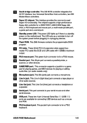
.... This purple 6-pin connector is a standby power on audio models only) 20 Microphone jack. This green LED lights up if there is for a PS/2 keyboard. ASUS P4SE Motherboard 1-5
.... This purple 6-pin connector is a standby power on audio models only) 20 Microphone jack. This green LED lights up if there is for a PS/2 keyboard. ASUS P4SE Motherboard 1-5

P4SE User Manual
Page 17
... mode, a reminder that you should shut down the system before removing of the following precautions before you install motherboard components or change any motherboard component P4SE ® P4SE Onboard LED LED1 ON Standby Power OFF Powered Off ASUS P4SE Motherboard 1-7
... mode, a reminder that you should shut down the system before removing of the following precautions before you install motherboard components or change any motherboard component P4SE ® P4SE Onboard LED LED1 ON Standby Power OFF Powered Off ASUS P4SE Motherboard 1-7

P4SE User Manual
Page 19
PCI slot 2 - shared - - shared AGP shared - - - ASUS P4SE Motherboard 1-9 PCI slot 4 - - - PCI slot 6 - Otherwise, conflicts will arise between two PCI groups. The following subsections describe the slots and the expansion cards that the ..." or that they support. 1.8.1 Configuring an expansion card After physically installing the expansion card, configure the card by adjusting the software settings. 1. 1.8 Expansion slots The P4SE motherboard has six (6) expansion slots. Onboard USB controller HC0 - - -
PCI slot 2 - shared - - shared AGP shared - - - ASUS P4SE Motherboard 1-9 PCI slot 4 - - - PCI slot 6 - Otherwise, conflicts will arise between two PCI groups. The following subsections describe the slots and the expansion cards that the ..." or that they support. 1.8.1 Configuring an expansion card After physically installing the expansion card, configure the card by adjusting the software settings. 1. 1.8 Expansion slots The P4SE motherboard has six (6) expansion slots. Onboard USB controller HC0 - - -

P4SE User Manual
Page 21
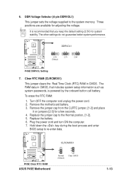
... DRAM 100MHz 133MHz 150MHz 160MHz 166MHz ON 12345 ON 12345 ON 12345 ON 12345 ON 12345 ON 12345 P4SE ® CPU 105MHz DRAM 140MHz P4SE CPU External Frequency Selection 108MHz 144MHz 112MHz 149MHz 133MHz 133MHz 133MHz 166MHz 100MHz 200MHz Set the CPU frequency ...Clock). CPU Frequency Selection (DSW1 Switches 1-5) This option tells the clock generator what frequency to jumper mode. P4SE ® KBPWR1 2 1 +5V 3 2 +5VSB (Default) P4SE Keyboard Power Setting ASUS P4SE Motherboard 1-11 To select the CPU external frequency using the DIP switches, ensure that can supply at least ...
... DRAM 100MHz 133MHz 150MHz 160MHz 166MHz ON 12345 ON 12345 ON 12345 ON 12345 ON 12345 ON 12345 P4SE ® CPU 105MHz DRAM 140MHz P4SE CPU External Frequency Selection 108MHz 144MHz 112MHz 149MHz 133MHz 133MHz 133MHz 166MHz 100MHz 200MHz Set the CPU frequency ...Clock). CPU Frequency Selection (DSW1 Switches 1-5) This option tells the clock generator what frequency to jumper mode. P4SE ® KBPWR1 2 1 +5V 3 2 +5VSB (Default) P4SE Keyboard Power Setting ASUS P4SE Motherboard 1-11 To select the CPU external frequency using the DIP switches, ensure that can supply at least ...
P4SE User Manual
Page 23
...seconds. 4. The RAM data in CMOS. Remove the motherboard battery. 3. Replace the jumper cap to the system memory. P4SE ® DDRVOL1 12 23 2.5V 2.7V (Default) 34 2.9V P4SE DDRVOL Setting 7. Clear RTC RAM (CLRCMOS1) This jumper clears the Real Time Clock (RTC) RAM in CMOS, that ... cord and turn ON the computer. 7. To erase the RTC RAM: 1. The other settings do not guarantee better system performance. P4SE ® P4SE Clear RTC RAM ASUS P4SE Motherboard CLRCMOS1 2 1 Normal (Default) 3 2 Clear CMOS 1-13 It is powered by the onboard button cell battery.
...seconds. 4. The RAM data in CMOS. Remove the motherboard battery. 3. Replace the jumper cap to the system memory. P4SE ® DDRVOL1 12 23 2.5V 2.7V (Default) 34 2.9V P4SE DDRVOL Setting 7. Clear RTC RAM (CLRCMOS1) This jumper clears the Real Time Clock (RTC) RAM in CMOS, that ... cord and turn ON the computer. 7. To erase the RTC RAM: 1. The other settings do not guarantee better system performance. P4SE ® P4SE Clear RTC RAM ASUS P4SE Motherboard CLRCMOS1 2 1 Normal (Default) 3 2 Clear CMOS 1-13 It is powered by the onboard button cell battery.

P4SE User Manual
Page 25
P4SE ® TIP: If the case-mounted LED does not light, try reversing the 2-pin plug. FLOPPY1 NOTE: Orient... power to PIN 1. Floppy disk drive connector (34-1 pin FLOPPY) This connector supports the provided floppy drive ribbon cable. 2. IDELED1 P4SE IDE Activity LED 3. The read and write activities of devices connected to the primary or secondary IDE connector cause this LED to prevent ... one end to the motherboard, connect the other end to the floppy drive. (Pin 5 is removed to light up. P4SE ® PIN 1 P4SE Floppy Disk Drive Connector ASUS P4SE Motherboard 1-15
P4SE ® TIP: If the case-mounted LED does not light, try reversing the 2-pin plug. FLOPPY1 NOTE: Orient... power to PIN 1. Floppy disk drive connector (34-1 pin FLOPPY) This connector supports the provided floppy drive ribbon cable. 2. IDELED1 P4SE IDE Activity LED 3. The read and write activities of devices connected to the primary or secondary IDE connector cause this LED to prevent ... one end to the motherboard, connect the other end to the floppy drive. (Pin 5 is removed to light up. P4SE ® PIN 1 P4SE Floppy Disk Drive Connector ASUS P4SE Motherboard 1-15

P4SE User Manual
Page 27
...) at +12V. Do not forget to connect the fan cables to act as a master by initiating data transfer. PWRFAN1 GND +12V Rotation P4SE ® P4SE 12-Volt Fan Connectors CPUFAN1 GND +12V Rotation CHASFAN1 Rotation +12V GND 7. P4SE ® P4SE SMBus Connector ASUS P4SE Motherboard SMB 1 FLOATING SMBCLK Ground SMBDATA +3V 1-17 These are not jumpers!
...) at +12V. Do not forget to connect the fan cables to act as a master by initiating data transfer. PWRFAN1 GND +12V Rotation P4SE ® P4SE 12-Volt Fan Connectors CPUFAN1 GND +12V Rotation CHASFAN1 Rotation +12V GND 7. P4SE ® P4SE SMBus Connector ASUS P4SE Motherboard SMB 1 FLOATING SMBCLK Ground SMBDATA +3V 1-17 These are not jumpers!

P4SE User Manual
Page 29
...ATXPWR connector, this motherboard requires that you are designed to fit these connectors in only one of the 4-pin device power plugs into the ASUS EZ Plug™ connector labeled AUX12V. If you connect the 4-pin ATX +12V power plug to provide sufficient power to an ATX ...+12V GND GND +5V AUX12V1 +12.0VDC +5VSB PWR_OK COM +5.0VDC COM +5.0VDC COM +3.3VDC +3.3VDC P4SE ® +12V DC ATX12V1 P4SE ATX & Auxiliary Power Connectors +12V DC COM Pin 1 COM ASUS P4SE Motherboard 1-19 Find the proper orientation and push down firmly until the connectors completely fit. Make sure that does...
...ATXPWR connector, this motherboard requires that you are designed to fit these connectors in only one of the 4-pin device power plugs into the ASUS EZ Plug™ connector labeled AUX12V. If you connect the 4-pin ATX +12V power plug to provide sufficient power to an ATX ...+12V GND GND +5V AUX12V1 +12.0VDC +5VSB PWR_OK COM +5.0VDC COM +5.0VDC COM +3.3VDC +3.3VDC P4SE ® +12V DC ATX12V1 P4SE ATX & Auxiliary Power Connectors +12V DC COM Pin 1 COM ASUS P4SE Motherboard 1-19 Find the proper orientation and push down firmly until the connectors completely fit. Make sure that does...

P4SE User Manual
Page 31
... models only) This connector supplies a front panel Line out jack for stereo output. ALOUT1 1 P4SE ® P4SE ALOUT Connector ALOUT1_LOUT_R BLOUT1_LOUT_L ALOUT1_LOUT_R BLOUT1_LOUT_L ASUS P4SE Motherboard 1-21 The S/PDIF Out module is not included in the motherboard package. +5V SPDIFOUT ...GND 13. SPDIF_OUT1 P4SE ® P4SE Digital Audio Connector 14. Connect one end of analog sound output. Line out...
... models only) This connector supplies a front panel Line out jack for stereo output. ALOUT1 1 P4SE ® P4SE ALOUT Connector ALOUT1_LOUT_R BLOUT1_LOUT_L ALOUT1_LOUT_R BLOUT1_LOUT_L ASUS P4SE Motherboard 1-21 The S/PDIF Out module is not included in the motherboard package. +5V SPDIFOUT ...GND 13. SPDIF_OUT1 P4SE ® P4SE Digital Audio Connector 14. Connect one end of analog sound output. Line out...

P4SE User Manual
Page 33
... a switch that controls the system power. Pressing the power switch while in the ON mode for rebooting the system without turning off the system power. ASUS P4SE Motherboard 1-23 • System Management Interrupt Lead (2-pin SMI) This 2-pin connector allows you to manually place the system into a suspend mode, or "green" mode...
... a switch that controls the system power. Pressing the power switch while in the ON mode for rebooting the system without turning off the system power. ASUS P4SE Motherboard 1-23 • System Management Interrupt Lead (2-pin SMI) This 2-pin connector allows you to manually place the system into a suspend mode, or "green" mode...

P4SE User Manual
Page 35
Chapter 2 This chapter gives information about the ASUS P4SE Binary Input/Output System (BIOS).This chapter includes updating the BIOS using the ASUS AFLASH BIOS that is bundled with the support CD. BIOS Information ASUS P4SE Motherboard 2-1
Chapter 2 This chapter gives information about the ASUS P4SE Binary Input/Output System (BIOS).This chapter includes updating the BIOS using the ASUS AFLASH BIOS that is bundled with the support CD. BIOS Information ASUS P4SE Motherboard 2-1

P4SE User Manual
Page 37
... file from the Internet (WWW or FTP) (see ASUS CONTACT INFORMATION on page x for example, A:\XXX-XX.XXX, then press . Save Current BIOS to the boot floppy disk you are sure that the new ... . At the "A:\" prompt, type AFLASH and then press . 4. Updating the BIOS Update the BIOS only if you created earlier. 2. Select 1. 5. To cancel this operation, press . ASUS P4SE Motherboard 2-3
... file from the Internet (WWW or FTP) (see ASUS CONTACT INFORMATION on page x for example, A:\XXX-XX.XXX, then press . Save Current BIOS to the boot floppy disk you are sure that the new ... . At the "A:\" prompt, type AFLASH and then press . 4. Updating the BIOS Update the BIOS only if you created earlier. 2. Select 1. 5. To cancel this operation, press . ASUS P4SE Motherboard 2-3

P4SE User Manual
Page 39
... your system using the BIOS Setup program so that the computer can scroll through the various submenus and make changes to the basic system configuration. ASUS P4SE Motherboard 2-5 When you start up the computer, the system provides you can recognize these changes and record them in the future. This section explains how...
... your system using the BIOS Setup program so that the computer can scroll through the various submenus and make changes to the basic system configuration. ASUS P4SE Motherboard 2-5 When you start up the computer, the system provides you can recognize these changes and record them in the future. This section explains how...

P4SE User Manual
Page 41
.... The sub-menu appears. Valid values for a field parameter. If you would within a sub-menu as shown on the left) appears to the main menu. ASUS P4SE Motherboard 2-7 To display a submenu, move between the hour, minute, and second fields. The format is hour, minute, second.
.... The sub-menu appears. Valid values for a field parameter. If you would within a sub-menu as shown on the left) appears to the main menu. ASUS P4SE Motherboard 2-7 To display a submenu, move between the hour, minute, and second fields. The format is hour, minute, second.

P4SE User Manual
Page 43
...] This field specifies the types of cylinders, heads and sectors per track for the drive. Refer to manually enter the IDE hard disk drive parameters. ASUS P4SE Motherboard 2-9 Configuration options: [All Errors] [No Error] [All but Keyboard] [All but Disk] [All but Disk/Keyboard] Installed Memory [XXX MB] This field automatically displays...
...] This field specifies the types of cylinders, heads and sectors per track for the drive. Refer to manually enter the IDE hard disk drive parameters. ASUS P4SE Motherboard 2-9 Configuration options: [All Errors] [No Error] [All but Keyboard] [All but Disk] [All but Disk/Keyboard] Installed Memory [XXX MB] This field automatically displays...

P4SE User Manual
Page 45
... internal hard disk drive monitoring technology. Modes 0 through 4 provide successive increase in the SMART monitoring feature may decrease system performance. Configuration options: [0] [1] [2] [3] [4] [5] [Disabled] 2.3.2 Keyboard Features ASUS P4SE Motherboard 2-11 Refer to the documentation that came with the hard drive to the highest number that when this field, set it manually. Configuration options...
... internal hard disk drive monitoring technology. Modes 0 through 4 provide successive increase in the SMART monitoring feature may decrease system performance. Configuration options: [0] [1] [2] [3] [4] [5] [Disabled] 2.3.2 Keyboard Features ASUS P4SE Motherboard 2-11 Refer to the documentation that came with the hard drive to the highest number that when this field, set it manually. Configuration options...

P4SE User Manual
Page 47
... not detected, the USB controller legacy mode is detected, the BIOS assigns IRQ12 to the PS/2 mouse. Otherwise, leave to [Enabled]. Configuration options: [Disabled] [Enabled] ASUS P4SE Motherboard 2-13 CPU VCore Setting [Auto] The [Manual] setting allows you set this field to [Enabled], BIOS reserves IRQ12, whether or not a PS/2 mouse is...
... not detected, the USB controller legacy mode is detected, the BIOS assigns IRQ12 to the PS/2 mouse. Otherwise, leave to [Enabled]. Configuration options: [Disabled] [Enabled] ASUS P4SE Motherboard 2-13 CPU VCore Setting [Auto] The [Manual] setting allows you set this field to [Enabled], BIOS reserves IRQ12, whether or not a PS/2 mouse is...


